Spanish
  Chinese
  Russian
  German
  French
  Japanese
  Portuguese
  Hindi
Hindi Research Article, J Polym Sci Appl Vol: 1 Issue: 2
Fabrication of Light Weight Mechanically Robust Short Carbon Fiber/Ethylene Methyl Acrylate Polymeric Nanocomposite for Effective Electromagnetic Interference Shielding
Poushali Bhawal, Tushar Kanti Das, Sayan Ganguly, Subhadip Mondal, Revathy Ravindren and Das NC*
Rubber Technology Center, Indian Institute of Technology, Kharagpur, India
*Corresponding Author : Das NC
Rubber Technology Center, Indian Institute of Technology, Kharagpur, India
Tel: + 91-3222 -283190
E-mail: ncdas@rtc.iitkgp.ernet.in
Received: June 15, 2017 Accepted: August 24, 2017 Published: August 28, 2017
Citation: Bhawal P, Das TK, Ganguly S, Mondal S, Ravindren R, et al. (2017) Fabrication of Light Weight Mechanically Robust Short Carbon Fiber/Ethylene Methyl Acrylate Polymeric Nanocomposite for Effective Electromagnetic Interference Shielding. J Polym Sci Appl 1:2.
Abstract
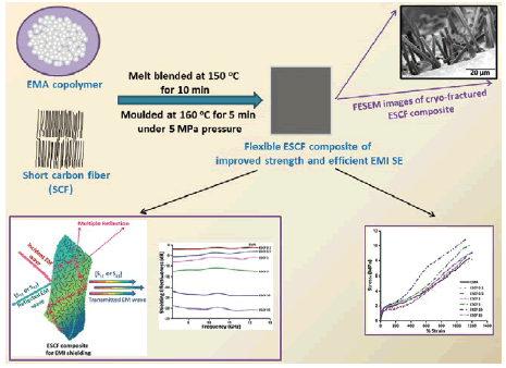
Short carbon fiber (SCF) filled ethylene methyl acrylate (EMA) nanocomposites of excellent mechanical strength and flexibility has been fabricated by using a facile and commercially feasible melt blending method to evaluate its electromagnetic interference shielding effectiveness (EMI SE) as well as the mechanical and thermal properties of the composites. Improved dispersion offers three dimensional interconnected networks within polymeric matrix to achieve lower percolation threshold of 3.10 wt%. Morphological analysis has been carried out by using field emission scanning electron microscope (FESEM) to reveal good dispersion of SCFs in EMA matrix even at a higher loading of 10 wt%. The influence of aspect ratio with increasing filler concentration on mechanical strength and electrical properties of composites has been explained by optical microscopic images. Experimental results demonstrate that an improved tensile strength of 37% in comparison with neat EMA and an increasing thermal stability along with excellent EMI SE of -23.9 dB has been achieved at 10 wt% SCF loading, which makes it a potentially flexible, light weight, mechanically robust, efficient EMI shielding material for commercial applications.
Keywords: Ethylene methyl acrylate; Short carbon fiber; Aspect ratio; Mechanical strength; Electromagnetic interference shielding effectiveness (EMI SE); Dispersion of fibrous filler
Graphical abstract
Introduction
Progressive implementation of modern technologies, especially high-frequency electronic devices such as microwave transmission, communication satellites, telephone, radio and fiber optics causes severe electromagnetic (EM) pollution in the society. Generated electromagnetic waves of the instruments result an electromagnetic interference (EMI), which not only affect the performance of other devices but also disturb human life [1,2]. Polymer nanocomposites, containing carbonaceous fillers, have drawn great interest in the present science and technological field for their improved electronic and shielding effectiveness (SE) altogether mechanical and thermal stability, easy processability, light weight, low cost and superior performances in automobiles, aerospace, defense and energy storage devices [3-6]. Incorporation of various carbon based fillers, such as carbon black, carbon nanotube (CNT), graphene, expandable graphite (EG) etc. although improves the electrical and shielding properties of composites but still now they have suffered through processing difficulties, poor dispersion, lower filler-polymer interactions, high cost etc [7-13]. Carbon fibers can improve the shielding effectiveness of composites through uniform dispersion in the matrix at low filler concentration [14]. Carbon nanofiber (CNF) and Short carbon fiber (SCF) are very well known fibrous filler of carbon fibers family and have been employed in polymer industry to improve the electrical properties of composites in commercial field of applications. Although CNF has been widely used with various polymer to improve their thermal, mechanical, electrical and EMI SE but dispersion of CNF in polymer matrices is very difficult because of their small diameter and very high surface area [15-23]. On the other hand, SCF improves the EMI SE of polychloroprene rubber composites at 20 phr loading [24]. Yang et al. observed that 5 wt% SCF lowered the electrical resistivity of LCP composites of 11th order magnitude and showed 41 dB EMI SE at 15 wt% loading [25]. Although incorporation of SCF improves electrical conductivity by lowering percolation threshold but it shows adverse effect on the mechanical properties of SCF filled PVDF composites for poor filler-polymer interaction [26]. Properties of composites depend on several factors, such as, nature of polymer and filler, aspect ratio of filler, uniform dispersion of filler in polymer matrix with loading, filler-filler and filler-polymer interaction, process of mixing, mixing time and temperature etc [6,27-40]. The above mentioned factors affect physical, thermal as well as electrical properties of the composites significantly.
Since addition of SCF deteriorates the mechanical properties of the composites, hence carbon black has been incorporated in SCF filled nitrile rubber to study the improvement of mechanical and electrical properties of the composites [41]. SCF has been also incorporated in blend system to investigate the effect on mechanical, electrical and shielding properties of composites [42]. Still now very less works have been reported on the improvement of electrical and EMI shielding effectiveness of SCF filled composites with moderate mechanical and thermal endurance without hampering the flexibility of composites. Therefore, we have been motivated to explore a new strategy for the development of cost effective, light weight, flexible SCF filled composites with improved EMI SE along with moderate mechanical and thermal stability.
Interesting features of semi-crystalline ethylene methyl acrylate (EMA) plays an important role to govern the properties of filled composites. Very high weather, ageing resistance and wide temperature range of application raises the demand of EMA in polymer field [43]. Very high strength to weight ratio and lower density compared to major plastics enhances the opportunity to choose EMA as the basic requisites for the fabrication of SCF filled EMA polymeric composites (ESCF) to achieve the required EMI SE and mechanical strength [44]. Ethylene vinyl acetate (EVA) is also very well-known thermoplastic in polymer industry, but much higher thermal, ageing and degradation resistance of EMA makes it advantageous over EVA in commercial applications. Polar and nonpolar backbone of EMA also facilitates the dispersion of SCF through the matrix for betterment of properties. Dispersion of nano-filler in polymer matrix is significantly governed by the mixing procedure. Over last decades, many researchers have been worked how the dispersion of carbon-fiber in polymer matrices are affected by the processing condition of melt blending and solution mixing [17,19,45-50]. Solution mixing generally used to fabricate composites for academic purpose and it also exhibits the problems of toxicity and pollution. Solution mixing gives improved end properties at very lower loading of filler, whereas increasing loading deteriorates the properties sometime with complete failure. Melt blending overcomes the demerits and plays very important role to fabricate composites for large scale production in industrial application costeffectively but long mixing time and very high shear of melt blending also deteriorates the conductivity of composites by reducing the aspect ratio of nanofibers. Henceforth, it is still a challenge to fabricate cost-effective, flexible short carbon fiber filled polymer composites to achieve superior EMI SE altogether moderate mechanical strength.
Thus, mixing of variable amount of carbonaceous fibrous filler in thermoplastic polymeric matrix by melt blending for the development of flexible composites with well dispersed nanofibers is an important technique to propel the work in this direction. In this work EMA is used as the base material and SCF of varying concentration has been incorporated to achieve mechanical, thermal stability with improve conductivity and EMI SE with increased dispersibility and compatibility of nanofiber with neat polymer. The result of mechanical, thermal, electrical and EMI SE analysis of ESCF composites (ESCF) confirm that ESCF can be used for commercial field of applications.
Experimental
Materials
Commercial ethylene methyl acrylate copolymer or EMA (Elvaloy® 1330) was purchased from Dupont, Mumbai to use as base material. It contains 30% methyl acrylate and melt flow index (MFI) is 3.0 g 10 min-1 (at 190 oC and 2.16 Kg) as per ASTM D1238. Conductive short carbon fiber (SCF) was obtained from Nanotech Private Limited, India. SCF has diameter = 7 μm, density = 1.8 g cm-3, electrical resistivity = 10-3 Ω cm and the fibers have been chopped at an average length of 4 mm.
Preparation of ESCF composites
ESCF composites were prepared by melt mixing in Brabender Plasticorder PLE-330. To fabricate ESCF composites variable amount SCF was incorporated separately in to neat EMA. Table 1 represents the composites of different loading of SCF. Mixing was carried out for 10 min at a fixed temperature of 150°C by maintaining a constant rotor speed of 60 rpm for all the composite samples. The compounded sheets were passed through two-roll mill to get a sheet like material. The sheets were then moulded in hydraulic press (Moore press, United Kingdom) under a pressure of 5 MPa and 160°C temperature for 5 min to obtain the final sheets thickness of 1 mm.
| Sample designation | EMA (wt%) | SCF (wt%) |
|---|---|---|
| EMA | 100 | 0 |
| ESCF 0.1 | 100 | 0.1 |
| ESCF 0.5 | 100 | 0.5 |
| ESCF 1 | 100 | 1.0 |
| ESCF 5 | 100 | 5.0 |
| ESCF 10 | 100 | 10.0 |
| ESCF 15 | 100 | 15.0 |
Table 1: Designation of the ESCF composites made, by adding variable amount of SCF in EMA.
Characterizations
Dispersion of SCF through polymeric matrix was observed from FESEM (Field Emission Scanning Electron Microscope, MERLIN of tungsten filament; Carl ZEISS, SMT, Germany) analysis. Mechanical properties of neat EMA and ESCF composites were conducted by using Universal tensile testing machine (Hounsfield H10 KS) at room temperature with a constant cross head speed of 500 mm min-1 (Table 2). All dumb-bell shaped specimens were tested by following the specification of ASTM D412 and ASTM D624 and the results were reported on the average value of three measurements. To study the effect of temperature on dynamic mechanical properties of pure EMA and filled composites, dynamic mechanical thermal analysis was carried out in dynamic mechanical analyzer (Mertavib 50N, France) by varying temperature range from -60 to +60°C under a constant heating range of 3°C min-1 with constant frequency of 10 Hz and 0.001% strain. Thermal properties, such as glass transition temperature (Tg) and melting temperature (Tm) were measured from differential scanning calorimeter (DSC Q2000 V24.10, TA Instruments, USA) within the temperature range of -80 to +100°C with heating rate of 10°C min-1 under nitrogen atmosphere. DC resistivity of SCF filled composites were determined at room temperature by using Agilent 4339 high resistance meter (electrical resistance ≥ 106 Ω) and Agilent 3440A 6½ digital multimeter (electrical resistance ≤ 99 × 106 Ω). Electromagnetic interference shielding effectiveness (EMI SE), return loss, absorption loss of the 3 mm thick rectangular composite samples were measured by using Vector Network Analyzer (N9926A, Agilent Technologies) in the X-band frequency region of 8.2-12.4 GHz. Composite samples were placed in a holder of matching dimension of X-band waveguide and connected with Vector Network Analyzer (VNA) to obtain the SE of composites.
| Sample designation | Tensile strength (MPa) | Elongation at break (%) | M@100%* (MPa) | M@200%* (MPa) | M@300%* (MPa) |
|---|---|---|---|---|---|
| EMA | 8.0 | 1168 | 1.7 | 2.1 | 2.1 |
| ESCF 0.1 | 8.3 | 1233 | 1.70 | 1.8 | 2.0 |
| ESCF 0.5 | 8.8 | 1220 | 1.9 | 2.2 | 2.5 |
| ESCF 1 | 9.1 | 1203 | 1.9 | 2.3 | 2.6 |
| ESCF 5 | 10.0 | 1170 | 2.1 | 2.4 | 2.7 |
| ESCF 10 | 10.9 | 1113 | 2.2 | 2.5 | 2.8 |
| ESCF 15 | 8.5 | 1130 | 1.4 | 1.6 | 1.9 |
*M@X% = Modulus at X% elongation
Table 2: Mechanical properties of pure EMA and filled ESCF composites.
Results and Discussion
Dispersion mechanism of short carbon fiber in polymer matrix during melt blending
Dispersion of carbon fiber (CF) in melt mixing technique depends on various factors, like, temperature, time, shearing action, pressure, rotor speed, amount of filler incorporation and nature of filler and polymer. Despite the above mentioned factors, Kasaliwal et al. described that dispersion and distribution of nano-filler in melt blending encompass with some inherent mechanism, such as, wetting, infiltration and flocculation [49]. Very high aspect ratio and Van-der Waals force of interaction are responsible for the formation of agglomerated carbon-fiber. Melt mixing at first helps to wet filler surfaces by molten polymer and the process has been considered as relatively fast process. Although quality of wetting is governed by the interfacial energy of carbon-fiber and polymer melt but good wetting is required to achieve the polymer infiltration in the aggregated structure of fibers. Shearing force of melt blending breaks down the agglomerated structure and also helps to wet the new developed filler surfaces by molten polymer. As a result, the aggregated carbon-fiber starts to distribute throughout the base matrix and reduction of length has been obtained depending on applied shear force. Shorten fiber further infiltrated by the polymer chains which assist in easy breakdown of smaller agglomerates in clusters and individual carbon-fiber. During melt mixing, molten polymer erodes carbon-fiber; as a consequence fibers become separated from their surfaces and dispersed through the base polymer. All the mentioned wetting, infiltration and erosion processes have been accelerated at lower viscosity of polymer; henceforth, higher temperature of mixing and high speed can give improved dispersion of carbon-fiber. On the contrary, high melt viscosity and shear stress can disperse carbon-fiber through breaking the fiber at comparatively lower temperature. The breakage reduces the aspect ratio of carbon-fibers and responsible for high electrical percolation of the composite material. Since, fibers are attached with polymers through physical adhesion; therefore, high temperature mixing is more favorable by balancing the rupture and erosion mechanism to minimize the damage of fiber length and results lower electrical percolation by the formation of networks of finely dispersed carbonfibers.
To follow the above mention mechanistic pathway of melt blending we fabricated the ESCF composites by maintaining temperature at 150°C and 60 rpm rotor speed. Since, breakage of fiber depends on shearing force; increasing filler concentration enhances the shearing force towards composite materials. Since shearing strength, viscosity of polymer and size of aggregates are the key factor to control shearing forces on agglomerates; lower filler concentration suffers through poor breakage for higher availability of space to rotate the fibers freely by lowering the shearing strength. Therefore, low filler concentration demonstrates inferior dispersion of SCF through the polymer matrix and results higher electrical resistivity for lower network structure in melt blending, which is also evidenced from FESEM and optical microscopic images. On the other hand, increasing concentration of SCF exhibits much higher shearing force on fiber agglomerates and polymer chains during melt blending and suppresses the free rotation of aggregates by increasing melt viscosity to starts easy degradation of SCF aggregates. FESEM images, optical microscopic analysis reveals that with increasing concentration of SCF the quality of dispersion also improves and achieves more homogeneity to result improved network structure through the base matrices by lowering electrical resistivity and percolation threshold up to a certain level of loading. At very high concentration of SCF Vander Waals forces of interaction predominates over shearing force even at higher temperature and it becomes very difficult to detach the agglomerates and results poor dispersion, which is also confirmed from the optical microscopic images.
Physico-mechanical behavior of ESCF composites
Stress-strain behavior of SCF filled ESCF composites are represented in Figure 1(a) , which demonstrates that mechanical properties of polymer composites depend on nature of base matrix and filler, filler loading, dispersion and distribution of filler through the matrix. Neat EMA has tensile strength of 8.0 MPA with an elongation at break of 1168%. SCF loading results an enhancement of tensile strength for a certain level of filler loading, after that deterioration of properties are observed at very high loading. From plot it is clear that maximum improvement of tensile strength of 10.9 MPa has been observed on 10 wt% loading with an elongation of 1113%, whereas 15 wt% SCF decreases tensile strength to 8.5 MPa by increasing elongation at break of 1130%. This improvement of tensile strength is observed as a combined effect of polymer matrix and filler interfacial adhesion and also the stiffness of fibrous filler. Elongation at break of filled polymer composites endorses the flexibility of material [51].

Figure 1: (a) Stress-strain plot of EMA and different amount of SCF filled ESCF composites and variation of (b) hardness and tensile strength of composites as a function of filler concentration.
Stress-strain plot of Figure 1(a) demonstrates that incorporation of filler exhibit lower elongation of filled composites progressively than neat EMA up to 10 wt% SCF, on the contrary 15 wt% SCF increases elongation at break. This decrement of elongation of filled composites than the base matrix results significant drop in ductility with an augmentation of stiffness of ESCF composites for the addition of fibrous filler [17].
In case of modulus of ESCF composites we can see that all composites follow the same trend of tensile strength. For 300% modulus, EMA shows the modulus value of 2.1 MPa, whereas ESCF 10 results a highest modulus of 2.8 MPa, i.e., exhibiting 33.3% improvement on modulus value. ESCF 15 reveals a decrement of properties may be as a result of aggregation or agglomerations of fibrous filler for their high inter filler interaction, which offers poor filler dispersion and lower filler-polymer interaction.
In previous research work it has been described that short carbon fiber offers poor filler-polymer interaction which accounts for lower mechanical strength of polymer composites [26,42,52]. There fore it is still now a challenging work to prepare flexible SCF filled composite with improved mechanical properties. Although modification of short carbon fiber results an improvement in mechanical properties but high oxidation deteriorates the strength of fibrous filler and reduces the aspect ratio, which is responsible for lower electrical conductivity [53]. Hence, choice of polymer, method of mixing and amount of filler loading is very essential parameter to govern the end properties of composites. As we already mentioned that in solution mixing improved dispersion of filler within base matrix is achieved at lower level of loading, whereas increasing concentration of fillers have a tendency to form aggregation or agglomeration within the matrix through Vander Waal’s interaction; where melt blending is preferable over solution mixing for high dosage of loading. In melt blending fillers are dispersed into the base polymer by the shearing action. Low filler concentration offers lower shearing action on the aggregated particles, which results comparatively poor dispersion of filler within the matrices or fillers remain in scattered fashion. Increasing filler loading enhances the shearing action in between filler-filler and polymer-filler particles which not only help to separate the aggregated particles for viscosity of melts, also improve the degree of mixing by breaking the aggregated particles through the suppression of free rotation [15]. Thus, the influence of fiber amount and aspect ratio on mechanical properties draws a great attention. It is often noticed that higher amount of fiber improves the strength and modulus altogether toughness if the polymer has low toughness [54].
At very low filler concentration of 0.5 wt% the stress-strain plot of Figure 1(a) shows poor improvement of tensile strength and modulus altogether an enhancement of elongation at break. This result may be explained by the combination of two factors: a) at very lower level of loading poor dispersion of filler in base matrix during melt blending and b) also EMA has a tendency to show strain-induced crystallization at higher strain because of its linear polyethylene domains, which reflects self-reinforcing behavior of matrix and accounts for higher tensile strength, modulus and improved elongation at break. Generally, tensile strength is governed by the fiber length than the amount of fiber [55,56]. Physical adhesion is the only interaction present between polymer and fiber to attach the fibers on polymer matrix. Investigations of failure mechanism reveal that under loading of tensile stress, crack initiates from the fiber ends and spread along fiber-matrix interface and finally reached to base polymer [57]. Fiber ends concentrate the stress in adjacent matrices and it can be decreased with matrix flow, interface debonding and matrix fracture. Therefore, deterioration is associated with number of fiber ends and fiber amount. Increasing loading demonstrates an improvement in mechanical properties with lowering elongation at break from 1 wt% loading and follow the same trend for ESCF 10 for improved mechanical mixing and better polymer-filler adhesion by physical bridging of SCF with. Improvement of tensile strength is also influenced by the high strength of carbon fiber. Comparatively high aspect ratio of ESCF 0.1 to ESCF 10 demonstrates lower fracture of fiber length which facilities the orientation of carbon-fiber towards flow direction to impart strength in filled composites, but much higher loading decreases the end properties.
During melt mixing fiber length decreases with increasing fiber content for fiber-fiber, fiber-polymer interaction and friction with the wall of processing equipment [58,59]. The very low aspect ratio of fiber reduces the strength of material. Thus, increasing fiber concentration reduces the tensile strength of composites after 10 wt% loading. In Composite ESCF 15, tensile strength is predominantly controlled by the fiber length rather than the fiber weight fraction, where very low aspect ratio reduces the tensile strength for poor physical adhesion of SCF and EMA [60,61].
Shore a hardness of EMA and all ESCF composites have been measured and shown in Figure 1(b). The plot states that increasing filler concentration enhances hardness of the composites than pure EMA having shore hardness of 55 shore A. Hardness increases progressively with increasing SCF concentration and results 72.3 shore A of ESCF 15. The moderate hardness of filled composites is suitable for commercial applications.
Morphological analysis
Morphological analysis of cryo-fractured ESCF composites has been performed by FESEM to investigate the dispersion and distribution of fibrous filler throughout the base polymer. Figure 2 (a-f) represents the typical cryo-fractured FESEM microphotographs of the different amount of SCF filled melt blended ESCF composites. At very lower loading from 0.1 wt% to 0.5 wt% we can observe that the fillers remain scattered in the matrix and are not able to construct conductive network through the matrix for experiencing lower shearing action in melt blending process by the lesser amount of SCF. The roughness of cryo-fractured surfaces is also lower than the other filled composites in Figure 2 (a-c), which signify poor interfacial adhesion of filler with matrix. FESEM images of increasing filler concentration of Figure 2 (d-f) reveal an improved dispersion of SCFs in neat EMA, where fillers are strongly embedded within matrix. The microphotographs demonstrate that increasing loading enhances surface roughness as well as porosity and voids in the matrix which signifies higher filler-polymer adhesion and offers improved mechanical properties of filled composites. Although fibrous fillers are individually pulled out from EMA surfaces at lower loading but at higher filler concentration individual SCFs are not pulled out from base matrix as a consequence of improved dispersion and physical interaction of fibrous filler with EMA for wetting of filler surfaces by the polymer melt and infiltration of polymer chains to separate the aggregated structure of SCF during melt blending. Increasing filler loading not only improve the mechanical properties of composites it also facilitates the generation of interconnected conductive network through the matrix which enhances the electrical conductivity as well as shielding properties of materials. Aspect ratio of fibrous fillers has an important role to govern mechanical, electrical properties and shielding effectiveness of SCF filled composites which can be explained by optical microscopic analysis.

Figure 2: (a-f) Field emission scanning electron microphotographs of cryo-fractured ESCF composites demonstrate the dispersion of variable amount fibrous filler (0.1 wt%, 0.5 wt%, 1 wt%, 5 wt%, 10 wt% and 15 wt% respectively) through the matrices to impart improved mechanical strength, electrical conductivity and efficient EMI SE in composite materials.
Effect of fiber length and aspect ratio in composite materials
Fiber length, aspect ratio and their distribution plays very important role to govern the mechanical, electrical and EMI shielding properties of composites. Variation of aspect ratio not only depends on the method of processing condition; it was also controlled by the amount of filler loading, viscosity of the system and the nature of polymer. Lower aspect ratio of fibrous filler generally decreases the electrical conductivity by inhibiting the formation of continuous interconnected network in the polymer matrix. Whereas higher aspect ratio assistances to generate continuous network for the improved electrical and shielding effectiveness by lowering the percolation threshold. Hence, fiber length is very important to control the end properties of composites. Since fiber diameter remains unchanged during processing, so maintaining the fiber length is a challenging work for filled composites.
Before mixing, short carbon fibers were cut with an average length of 4 mm. Very low bending strength and brittle nature of short carbon fibers have a tendency to undergo break down during mixing with polymer. High filler concentration increases the viscosity of filled material to experience higher shearing action for breakdown of fiber length.
Figure 3(a-g) represents the typical optical microscopic images of SCF (before mixing) and SCF filled EMA composites with increasing filler of 0.1 wt%, 0.5 wt%, 1 wt%, 5 wt%, 10 wt% and 15 wt% respectively. Variation of fiber length against number of fiber with increasing filler concentration is shown in Figure 3(h-l) by using Image J software. Microscopic images reveal that SCFs are randomly distributed in the matrix and at very low filler concentration and they remain separated from each other. The plot demonstrates that although increasing filler concentration reduces the average length but the effect was not significant upon 10 wt% loading. Whereas, at 15 wt% loading comparatively lower aspect ratio of SCFs are obtained for the very high shearing action and results in deterioration of mechanical properties of the composites [42]. On the contrary very high concentration of filler forms dense mesh through interconnected network by decreasing inter-particle gap which enhances the shielding effectiveness of composite materials. Increasing SCFs results more closed packed structure but the improvement becomes marginal after a certain level of loading (here 10 wt%) as a consequence of already framed network structure which only increases the number of continuous path and sometime shows poor results in mechanical and electrical properties for lowering average length and aspect ratio of SCF.

Figure 3: (a-g) SCF (before mixing) and SCF filled EMA composites with increasing filler of 0.1 wt%, 0.5 wt%, 1 wt%, 5 wt%, 10 wt% and 15 wt% respectively. Variation of Short carbon fiber length of (h) pure SCF (before mixing); (i-l) with increasing filler concentration of SCFs in ESCF 1, ESCF 5, ESCF 10 and ESCF 15 respectively. (m) Extent of fibrous filler breakage vs filler concentration of ESCF composite.
The extent of fibrous filler breakage can be determined from the following equation [42]:
Extent of fiber breakage = [(Lo – Lf)/Lo] × 100 (1)
Where, Lo = length of fiber befor mixing, Lf = length of fiber after mixing respectively. Figure 3 (m) represents the plot of extent of fiber breakage vs filler concentration and states that increasing filler concentration reduces the fiber length and aspect ratio as a result of higher viscosity of polymer matrix.
Dynamic Mechanical Thermal Analysis (DMTA)
Dynamic mechanical thermal analysis has been performed to study the relaxation behavior of ESCF composites filled with variable amount of SCF by evaluating the storage modulus (E’) and tan δ of neat polymer and composites materials. Storage modulus is defined as the modulus of elastic part of polymeric material, whereas tan δ represents the damping property of material and described by the ratio of loss modulus and storage modulus. EMA, being a semi-crystalline polymer show different response towards dynamic loading at different temperature. Incorporation of fibrous filler also affects the crystalline property of base polymer. Figure 4(a) and 4(b) demonstrates the variation of E’ and tan δ against temperature of filled composites and pure EMA respectively. Figure 4(a) demonstrates that at low temperature region (i.e., ~-60°C) all the filled ESCF composites and pure EMA have improved storage modulus value because of limited or restricted molecular mobility of polymer chains and crystalline backbone of EMA. With the attainment of glass temperature all the filled and pure material unveil a large drop of E’ value for phase transition from rigid glassy to flexible rubbery state. In glassy state the molecular chains have restricted motion which move freely in rubbery state. As a consequence the storage modulus value of both pure and filled materials deteriorates with increasing temperature. That’s why Figure 4(a) reveals that increasing temperature deteriorates the storage modulus value of both the filled and pure system than glassy region but filler incorporation gives higher storage modulus (E’) value of the filled composites than neat EMA. Addition of SCF results some interaction of filler with EMA through physical adhesion, which enhances the dynamic mechanical property of the filled composites. Amount of fiber and fiber aspect ratio also influences the dynamic mechanical property of the composite materials. With incorporation of higher amount of filler SCF exhibits much higher shear action, which reduces the aspect ratio in higher extent for higher filler loaded composites in comparison to lower amount of filler loaded composites. Small sized fillers are unable to impart stiffness to the base polymer and results smaller storage modulus value. Thus although incorporation of filler enhances the storage modulus value but the extent of improvement is observed at an optimal breakage of fiber length after that marginal or very poor improvement has been observed. This improvement of E’ value is observed up to 10 wt% SCF, after that a certain deterioration of E’ value is observed. Generally semicrystalline polymers show glass transition with increasing temperature as a consequence of the motion of amorphous part. Incorporation of fibrous filler offers higher sustainability and withstanding ability for improved E’ value of the filled composites than the neat EMA even at high temperature region [62]. The maximum tan δ value of tan δ vs temperature plot is considered as the glass transition temperature (Tg) of the corresponding material. Figure 4(b) provides higher tan δ value of filled ESCF composites up to 10 wt% SCF loading than neat EMA but very high filler loading (15 wt%) results a decrement in Tg value. Tan δ versus temperature plot shows that neat EMA has α and β peak, where α peak is observed at +28.0°C for inception of molecular motion and β peak at -23.2°C for the onset movement of methyl acrylate groups [63]. Figure 4(b) demonstrates that 10 wt% SCF loading enhances Tg of ESCF 10 at -17.1 oC (also the same trend is observed in DSC analysis) with lower tan δ magnitude in comparison to pure polymer for very high filler-polymer interaction through physical bridging and restrict the molecular mobility of polymer chains to improve the Tg of composites [62,64,65]. Increasing filler concentration also broadens the tan δ peak at higher temperature side. Unrestricted polymer segments try to maintain the glass transition temperature of bulk EMA, whereas polymer chain adjacent to the SCF attempt to restrict the mobility of polymer chain and increases the Tg of materials [66]. On the contrary very high loading (15 wt%) results lower glass transition temperature for poor filler-polymer interaction due to improper dispersion of SCF in EMA matrix and lower aspect ratio of SCF. Since tan δ peak is responsible for the damping character of material, hence it is evidenced that control filler loading plays an important role to govern the end properties of filled composites.

Figure 4: Variation of (a) storage modulus (E') and (b) loss tangent (tan δ) of neat EMA and SCF filled composites against temperature.
Study of Differential Scanning Calorimetry (DSC)
Glass transition temperature (Tg) and crystalline melting point (Tm) of neat polymer and filled composites can be easily determined from DSC analysis. Figure 5 represents the 2nd heating DSC thermogram of pure EMA and different amount of SCF loaded ESCF composites. DSC plot of Figure 5 clearly demonstrates that increasing filler enhances Tg of filled composites about 5.0°C than neat EMA on 10 wt% SCF loading (ESCF 10) and the data are summarized in Table 3. Increasing Tg of filled composites are obtained as a result of restricted movement of polymer chains for high interfacial interaction between EMA and SCF up to 69.3% breakage of carbon fiber, whereas 78.4% breakage of SCF shows decrement of glass transition temperature of filled composites during melt blending, the same trend is also observed in DMA analysis [65,67]. The result demonstrates that like other properties Tg of filled composites is also influenced by the amount as well the aspect ratio of SCF. A likely explanation is that, comparatively higher aspect ratio of fibrous filler can easily attach on the polymer surfaces through physical adhesion and restrict the mobility of polymer chain to exhibit higher glass transition temperature, while lower aspect ratio (corresponding to lower chain length) offers poor dispersion and interaction of fibrous fillers with polymer matrices. As a consequence increasing concentration of SCF at first show an improvement of Tg of filled composites progressively up to an optimal level of 10 wt% loading followed by a decrement at 15 wt% of SCF, which manifests that loading of fibrous filler, fiber length and aspect ratio are very important parameter to govern the end properties of SCF filled EMA composites. This improved thermal stability broadened the application of filled ESCF composites at higher temperature region than the pure EMA matrix for 10 wt% loading. Hence, control loading of nanofiller is still now a challenging approach for melt blending for betterment of properties. Table 3 represents that incorporation of SCF does not show any significant improvement in the melting temperature (Tm) of filled composites, which is very much similar with the other SCF filled thermoplastic polymer composites [68].

Figure 5: Second heating DSC thermogram of EMA and 0.1 wt%, 0.5 wt%, 1 wt%, 5 wt%, 10 wt% and 15 wt% short carbon fiber filled ESCF composites.
| Sample designation | Tg (oC) | Tm (oC) |
|---|---|---|
| EMA | -34.1 | 83.5 |
| ESCF 0.1 | -33.7 | 83.4 |
| ESCF 0.5 | -33.9 | 83.9 |
| ESCF 1 | -32.8 | 83.8 |
| ESCF 5 | -31.6 | 84.6 |
| ESCF 10 | -29.2 | 84.3 |
| ESCF 15 | -30.6 | 84.2 |
Table 3: Glass transition temperature (Tg) and melting temperature (Tm) of neat EMA and ESCF composites obtained from DSC analysis.
Analysis of DC conductivity
Incorporation of conductive fillers in insulating polymer matrix results an increment of electrical conductivity of filled composites by the formation of conductive network through materials. Figure 6 represents the changes of DC conductivity of neat EMA with filler loading. Pure EMA has very low conductivity of 10-16 S cm-1 and shows very marginal change at low filler loading of 0.1 wt%. From 1.0 wt% loading a progressive change is noticed in DC conductivity of the composites, which increases continuously upon 10 wt% loading and has been reflected in Figure 6 for the construction of interconnected conductive network of fibrous filler. Electrical conductivity of SCF filled composites is also governed by the fiber amount, length of fiber, their aspect ratio and distribution through the base polymer matrices [42]. Melt blending offers improved degree of dispersion of SCFs in matrix with increasing filler concentration by disintegrating the filler particles through shearing action and forms very high interconnected conductive mesh network to increase the conductivity of filled composites. Henceforth, melt blended ESCF 10 exhibits conductivity of 10-5 S cm-1. The critical filler concentration at which the composite changes from an insulating polymer in to a semiconducting or conducting material for the ease of formation of continuous fillerfiller network inside polymer matrix is known as critical percolation threshold [69]. Comparatively low filler concentration exerts lower shearing action during melt blending and offers high aspect ratio to fibrous filler to facilitate the generation of continuous conducting path through improved dispersion and distribution of filler. After percolation changes of conductivity with filler become very marginal as the combination of following two factors; i) completion of network formation at high filler concentration and ii) high filler concentration experiences very high shearing action during melt blending, which deteriorates the length of SCF to gives lower aspect ratio and poor tendency to form conductive network through the polymer matrices. As a result increasing filler concentration is not able to improve the electrical conductivity very high level after a certain amount of filler loading. Therefore it is preferable to maintain the filler concentration and their initial length during melt mixing.

Figure 6: Plot of DC conductivity of ESCF composites as a function of SCF loading. Inset: best fitted straight line is obtained by using power law equation of log σ against log (p–pc), which gives percolation threshold of pc = 3.1 wt% and t = 2.81.
Percolation threshold of filled composites can be obtained by the power law equation of classical theory as follows [15]:
σ(p) = σo(p-pc)t for p > pc (2)
Where, σ(p) = DC conductivity of composite, σo = constant quantity, p = filler weight fraction, pc= filler weight fraction at percolation threshold and t = critical exponent.
pc and t can be evaluated from the best fitted log-log plot of σ(p) vs (p-pc) and shown in Figure 6 inset. Critical exponent‘t’ has been calculated from the slope of best fitted curve and the value becomes t = 2.81, with respective percolation threshold of pc = 3.1 wt% from the intercept. Therefore it can be stated that addition of SCF in EMA enhances the electrical conductivity up to certain loading which helps to improve the shielding effectiveness of composites as well as enhances the mechanical strength and thermal stability for increased commercial viability.
Analysis of Electromagnetic Interference Shielding Effectiveness (EMI SE)
EMI SE is the measure of attenuation of radiated electromagnetic waves by the shielding materials. Electromagnetic shielding efficiency is measured as the cumulative result of reflection loss, absorption loss and multiple reflection loss at the interfaced of shielding material and mathematically represented as [70-72]:
EMI SET (dB) = 10 log10 (PT/PI) = SER + SEA + SEM (3)
Where PT and PI is the transmitted and incident electric or magnetic field intensity of electromagnetic radiation, SER, SEa, SEM represents the reflection, absorption and multiple reflection through the interfaces.
Scattering parameters S11 (or S22) and S12 (or S21) are used to determine the transmittance (T), reflectance (R) and absorbance (A) of electromagnetic waves as follows
T = |S12|2 = |S21|2 (S12 or S21= transmission coefficient) (4)
R = |S11|2 = |S22|2 (S11 or S22 = reflection coefficient) (5)
In generally the multiple reflection term is ignored when SEA≥10 dB and total EMI shielding becomes [73]:
SMI SET = SEr + SEA (6)
Polymers are generally insulating in nature and show very poor shielding effectiveness. Incorporation of filler generates conductive network to resist the electromagnetic pollution of any external source. Fiber length, aspect ratio and distribution of filler in base polymer play important role to control the electrical property and electromagnetic interference (EMI) shielding effectiveness of composite material. During mixing fiber diameter remain constant only fiber length changes as a result of fiber-fiber interaction, fiber-polymer interaction and contact with the surface of processing equipment [74]. Lower aspect ratio of fiber has a reverse effect on the electrical property; because longer length of fiber can easily form conductive network through the system and reduces the electrical percolation, whereas lower aspect ratio of fiber reduces the tendency to form network through the system and gives higher percolation [75]. EMI shielding effectiveness also depends on the formation of dense conductive filler network through the base matrices, but the influence of the aspect ratio of fibrous filler on EMI shielding is completely different from the electrical property.
To understand the effect of variable amount of fibrous filler loading in a thermoplastic material EMI SET of pure EMA and ESCF composites have been measured against variable filler loading within the X band frequency range of 8.2 - 12.4 GHz and shown in Figure 7(a). The plot clearly demonstrates that pure EMA having shielding effectiveness of 1.75 dB acts as transparent towards EM (electromagnetic) radiation, whereas filler loading progressively enhances the shielding effectiveness of filled composites with frequency and results SE of 38.7 dB on 15 wt% SCF loading. Improved SE is the result of interaction of incident radiation with dense conductive network structure of SCF, which reduces the perforation of filled composites through better dispersion of fibrous filler by melt blending. For a particular loading, aspect ratio of fibrous filler changes the shielding effectiveness of a material proportionately; increasing aspect ratio accelerates the formation of conductive network, whereas lower aspect ratio adversely affect the shielding effectiveness for less tendency to form conductive network. On the other hand, variable loading of fibrous filler plays two opposite effect; i) increasing concentration of filler enhances the tendency to form dense network structure to give enhanced EMI shielding, ii) incorporation of filler results higher breakage of fibrous length which suffers through the formation of network structure as well as mechanical, thermal and electrical properties. Therefore, we have to select the material depends on their utmost properties and application fields.

Figure 7: Variation of (a) EMI SE of ESCF composites with variable filler concentration against X-band frequency of 8.2 GHz to 12.4 GHz; (b) SET, SEA, SER and (c) skin depth of pure EMA and filled ESCF composites as a function of SCF loading at fixed frequency of 10 GHz.
Further study has been carried out by evaluating the changes of SET, SEA and SER with filler concentration at a fixed frequency of 10 GHz in Figure 7(b). SET, SEA and SER of all composites increase continuously with filler loading, but the enhancement of SET is very much relevant with the increase of SEA. SET increases from -2.17 dB to -30.73 dB with increasing filler of 0.1 wt% to 15 wt% and SEA increases from -0.85 dB to -22.91 dB for the same concentration of filler, whereas SER does not show significant improvement of SE on SCF loading. Absorption depends shielding mechanism of filled composites are observed due to the formation of fine conductive mesh by SCF in the base matrices, which augments the absorptivity of EM waves in the system by decreasing the perforation through close packing and signify that amount of filler predominate the shielding effectiveness over the aspect ratio of SCF with deteriorating the mechanical strength of composite after 10 wt% of loading. Shielding effectiveness also governed by the increasing energy consumption and high mobility of SCF electrons on application of electric fields. Absorption mechanism generally influenced by conductivity and polarization of filled composites. In ESCF presence of defects, interfaces and functional groups intensifies the polarizability of filled composites [15]. Increasing filler concentration reduces the mesh size but enhances the thickness of absorbing materials which act as absorbing sites to improve the shielding effectiveness. Therefore it is very difficult to determine the optimal SCF breakage to achieve the effective shielding effect of variable filler loaded composites without considering the sustainability of filled composites. Considering the above mentioned factors ESCF 10 can be considered as the requisite composite, which contain the optimal SCF breakage to give effective shielding effect with improved mechanical and thermal stability. Figure 3(m) divulges that although 78.4% breakage of SCF exhibits improved EMI shielding but there was deterioration of thermal and mechanical stability of the composites, while 69.3% SCF breakage of ESCF 10 composite can be referred as the optimal SCF breakage required to provide enhanced EMI shielding effectiveness of -23.8 dB with absorption efficiency of 77.1% in comparison to reflection efficiency of 12.47% and 99% blocking of electromagnetic radiation in X-band frequency region altogether 36.2% improvement of tensile strength property and ~ 5°C improvement of glass transition temperature.
Influence of skin depth on Electromagnetic Interference shielding effectiveness
Primary EMI shielding mechanism is influenced by the reflection, followed by the secondary mechanism of absorption. Beyond these two mechanisms another important shielding mechanism is multiple reflections, which describes the reflection obtained from various surfaces and interfaces of the shield material. Multiple reflections require the presence of large surface or interfaces of shield. Porous material or foam contains large surface area, whereas composite material containing filler of large surface area are the suitable example of materials having large interfaces [76]. Multiple reflection loss can be ignored when the difference between reflecting surfaces and interfaces is higher in comparison to the skin depth. On the contrary it reduces the overall shielding effectiveness when the shielding depth is thinner than skin depth [77]. Therefore, skin depth (δ) is an essential phenomenon to control the shielding effectiveness of composite materials having different concentration of filler (Figure 8). Skin depth of composite can be described as the depth at which the EM radiation decreased to 1/e of incident radiation and mathematically defined as [78,79]:

Figure 8: Pictorial representation of Electromagnetic Interference Shielding mechanism of ESCF composites.
δ = 1/(πfμα)1/2 = -8.68 (t/SEA) (7)
Where, t represents the thickness of nanocomposites, f, μ and σ is the frequency, magnetic permeability (μoμr; where μr is the relative magnetic permeability and μo = 4π × 10-7 Hm-1) and electrical conductivity in Ω-1m-1 respectively. Equation (7) clearly depicts that increasing frequency, electrical conductivity and magnetic permeability decreases the skin depth of composite materials. The effect of filler concentration on skin depth of composites at a fixed frequency of 10 GHz is demonstrated in Figure 7(c). The plot of skin depth against filler loading describes that skin depth decreases with filler concentration. ESCF 0.1 has a skin depth of 27.1 mm which reduces to 1.1 mm upon 15 wt% SCF incorporation. This result also satisfies equation (7) in terms of electrical conductivity as well as fiber aspect ratio. Incorporation of SCF from 0.1 wt% to 15 wt% enhances the shielding effectiveness of composites materials, but it decreases the skin depth of the composites of ESCF 0.1 to ESCF 15 from 27.1 mm to 1.1 mm. Although the improvement of conductivity after 10 wt% is marginal but the changes of skin depth is much significant from 1.4 mm to 1.1 mm. Figure 3(b-g) and (i-l) reveals that though incorporation of filler reduces the aspect ratio of SCF for high shearing action during melt blending, but it imparts positive effect on the skin depth, where increasing SCF concentration reduces the skin depth through the formation of dense conductive network structure in the composites. As we already mentioned that the combined effect of filler loading and aspect ratio influences the EMI shielding effectiveness of different SCF loaded composites, Figure 7(c) demonstrates that the same factor is also accountable for the variation of skin depth with filler loading. The experimental result describes that before and after percolation threshold a continuous improvement of EMI SE is observed as a consequence of interconnected network of SCF through the matrix, which is contradictory with the conductivity of composites and the composites are very much effective for the commercial applications of improved EMI shielding.
Conclusion
In this study, we developed the SCF filled flexible elastomeric composites to improve the electrical conductivity and mechanical property through a non-hazardous solvent free melt mixing process. Melt blending is very much cost-effective and commercially viable approach to give good dispersion of fibrous fillers through the matrix for achieving lower percolation threshold of 3.1 wt% and efficient EMI SE. Morphological analysis (FESEM and Optical Microscope) reveals that increasing filler concentration enhances the dispersion of fibrous filler and offers better filler-polymer interface adhesion to give improved mechanical strength with flexibility, thermal stability and also good conductivity by the formation of 3D networks. Stress-strain plot demonstrates the nature of polymer composites inhibits the tendency to form yielding and necking, compared to some earlier reported result, by offering higher polymer-filler adhesion and improved mechanical strength of 37% than neat EMA by maintain the optimal SCF breakage of 69.3%. Along with superior mechanical strength ESCF composite also exhibits EMI SE of -23.83 dB only on 10 wt% SCF loading where the shielding efficiency is governed by the absorption phenomenon via maintaining the concentration of filler as well as the thickness of material. DMA result reflects that storage modulus progressively increases with filler concentration and shows opposing effect with temperature. DSC and DMA analysis also confirms that addition of fibrous fillers marginally increases the glass transition temperature of filled polymer composites by restricting the movement of polymer chains. Henceforth, our experimental works can be envisaged as an excellent method to prepare mechanically strong, thermally stable, highly efficient EMI SE materials for the application in cost-effective electro-mechanical, techno commercial appliances, where improved mechanical strength and moderate thermal stability are essential necessities.
Acknowledgements
This work was funded by the Science and Engineering Research Board (SERB), Department of Science and Technology (DST), Ministry of Science and Technology, Govt. of India (ECR/2016/000048).
References
- Li Y, Shen B, Yi D, Zhang L, Zhai W, et al. (2017) The influence of gradient and sandwich configurations on the electromagnetic interference shielding performance of multilayered thermoplastic polyurethane/graphene composite foams. Compos Sci Technol 138: 209-216.
- Farukh M, Singh AP, Dhawan S (2015) Enhanced electromagnetic shielding behavior of multi-walled carbon nanotube entrenched poly (3, 4-ethylenedioxythiophene) nanocomposites. Compos Sci Technol 114: 94-102.
- Nayak L, Rahaman M, Khastgir D, Chaki T (2011) Thermal and electrical properties of carbon nanotubes based polysulfone nanocomposites. Polym Bull 67: 1029.
- Hussain F, Hojjati M, Okamoto M, Gorga RE (2006) Review article: polymer-matrix nanocomposites, processing, manufacturing, and application: an overview. J Compos Mater 40: 1511-1575.
- Li CY, Li L, Cai W, Kodjie SL, Tenneti KK (2005) Nanohybrid shishâ€Âkebabs: Periodically functionalized carbon nanotubes. Adv Mater 17: 1198-1202.
- Flandin L, Prasse T, Schueler R, Schulte K, Bauhofer W, et al. (1999) Anomalous percolation transition in carbon-black–epoxy composite materials. Phys Rev B: Condens Matter 59: 14349-14355.
- Colbert DT (2003) Single-wall nanotubes: a new option for conductive plastics and engineering polymers. Plast Addit Comp 5: 8-25.
- Luo DCX (1996) Electromagnetic interference shielding reaching 130 dB using flexible graphite. Carbon 34: 1293-1303.
- Bigg D (1987) The effect of chemical exposure on the EMI shielding of conductive plastics. Polym Compos 8: 1-7.
- Li N, Huang Y, Du F, He X, Lin X, et al. (2006) Electromagnetic interference (EMI) shielding of single-walled carbon nanotube epoxy composites. Nano lett 6: 1141-1145.
- Liang J, Wang Y, Huang Y, Ma Y, Liu Z, et al. (2009) Electromagnetic interference shielding of graphene/epGeorge JJ, Bhowmick AK (20oxy composites. Carbon 47: 922-925.
- Enríquez E, de Frutos J, Fernández J, De la Rubia M (2014) Conductive coatings with low carbon-black content by adding carbon nanofibers. Compos Sci Technol 93: 9-16.
- Dang ZM, Shehzad K, Zha JW, Mujahid A, Hussain T, et al. (2011) Complementary percolation characteristics of carbon fillers based electrically percolative thermoplastic elastomer composites. Compos Sci Technol 72: 28-35.
- Yang S, Chen C, Parng S (2002) Effects of conductive fibers and processing conditions on the electromagnetic shielding effectiveness of injection molded composites. Polym Compos 23: 1003.
- Mondal S, Nayak L, Rahaman M, Aldalbahi A, Chaki TK, et al. (2017) An effective strategy to enhance mechanical, electrical, and electromagnetic shielding effectiveness of chlorinated polyethylene-carbon nanofiber nanocomposites. Composites Part B 109: 155-169.
- Al-Saleh MH (2016) Electrical and electromagnetic interference shielding characteristics of GNP/UHMWPE composites. J Phys D: Appl Phys 49: 195302.
- Al-Saleh MH, Sundararaj U (2009) A review of vapor grown carbon nanofiber/polymer conductive composites. Carbon 47: 2-22.
- Nayak L, Khastgir D, Chaki TK (2013) A mechanistic study on electromagnetic shielding effectiveness of polysulfone/carbon nanofibers nanocomposites. J Mater Sci 48: 1492-1502.
- Varela-Rizo H, de Oca GM, Rodriguez-Pastor I, Monti M, Terenzi A, et al. (2012) Analysis of the electrical and rheological behavior of different processed CNF/PMMA nanocomposites. Compos Sci Technol 72: 218-224.
- Nie Y, Hübert T (2011) Effect of carbon nanofiber (CNF) silanization on the properties of CNF/epoxy nanocomposites. Polym Int 60: 1574-1580.
- George JJ, Bhowmick AK (2009) Influence of matrix polarity on the properties of ethylene vinyl acetate–carbon nanofiller nanocomposites. Nanoscale Res Lett 4: 655.
- Kumar S, Rath T, Mahaling R, Reddy C, Das C, et al. (2007) Study on mechanical, morphological and electrical properties of carbon nanofiber/polyetherimide composites. Mater Sci Eng: B 141: 61-70.
- Kumar S, Rath T, Mahaling R, Das C (2007) Processing and characterization of carbon nanofiber/syndiotactic polystyrene composites in the absence and presence of liquid crystalline polymer. Composites Part A 38: 1304-1317.
- Jana P, Mallick A, De S (1991) Electromagnetic interference shielding by carbon fibre-filled polychloroprene rubber composites. Composites 22: 451-455.
- Yang S, Lozano K, Lomeli A, Foltz HD, Jones R (2005) Electromagnetic interference shielding effectiveness of carbon nanofiber/LCP composites. Composites Part A 36: 691-697.
- Ram R, Rahaman M, Khastgir D (2014) Mechanical, electrical, and dielectric properties of polyvinylidene fluoride/short carbon fiber composites with lowâ€Âelectrical percolation threshold. J Appl Polym Sci 3: 131.
- Krupa I, Chodák I (2001) Physical properties of thermoplastic/graphite composites. Eur Polym J 37: 2159-2168.
- Fan L, Dang Z, Nan CW, Li M (2002) Thermal, electrical and mechanical properties of plasticized polymer electrolytes based on PEO/P (VDF-HFP) blends. Electrochim Acta 48: 205-209.
- Yang L, Schruben DL (1994) Electrical resistivity behavior of moldâ€Âcast metalâ€Âfilled polymer composites. Polym Eng Sci 34: 1109-1114.
- Thomas PS, Abdullateef AA, Al-Harthi MA, Atieh MA, De S, et al. (2012) Electrical properties of natural rubber nanocomposites: effect of 1-octadecanol functionalization of carbon nanotubes. J Mater Sci 47: 3344-3349.
- Das N, Chaki T, Khastgir D (2002) Effect of processing parameters, applied pressure and temperature on the electrical resistivity of rubber-based conductive composites. Carbon 40: 807-816.
- Premphet K, Horanont P (2000) Phase structure of ternary polypropylene/elastomer/filler composites: effect of elastomer polarity. Polymer 41: 9283-9290.
- Rahaman M, Chaki T, Khastgir D (2011) Development of high performance EMI shielding material from EVA, NBR, and their blends: effect of carbon black structure. J Mater Sci 46: 3989-3999.
- Chahal R, St. Pierre L (1962) Interfacial phenomena in macromolecular systems. ii. relaxation modulus of uncrosslinked silica-polydimethylsilosane composites. Macromolecules 2: 193-197.
- Chung DDL (2012) Carbon materials for structural self-sensing, electromagnetic shielding and thermal interfacing. Carbon 50: 3342-3353.
- Jing X, Zhao W, Lan L (2000) The effect of particle size on electric conducting percolation threshold in polymer/conducting particle composites. J Mater Sci Lett 19: 377-379.
- Chou KS, Huang KC, Shih ZH (2005) Effect of mixing process on electromagnetic interference shielding effectiveness of nickel/acrylonitrile–butadiene–styrene composites. J Appl Polym Sci 97: 128-135.
- Borse NK, Kamal MR (2006) Melt processing effects on the structure and mechanical properties of PAâ€Â6/clay nanocomposites. Polym Eng Sci 46: 1094-1103.
- Gatos KG, Thomann R, Kargerâ€ÂKocsis J (2004) Characteristics of ethylene propylene diene monomer rubber/organoclay nanocomposites resulting from different processing conditions and formulations. Polym Int 53: 1191-1197.
- Kalyon DM, Birinci E, Yazici R, Karuv B, Walsh S (2002) Electrical properties of composites as affected by the degree of mixedness of the conductive filler in the polymer matrix. Polym Eng Sci 42: 1609-1617.
- Pramanik P, Khastgir D, Saha T (1992) Conductive nitrile rubber composite containing carbon fillers: studies on mechanical properties and electrical conductivity. Composites 23: 183-191.
- Rahaman M, Chaki TK, Khastgir D (2011) Highâ€Âperformance EMI shielding materials based on short carbon fiberâ€Âfilled ethylene vinyl acetate copolymer, acrylonitrile butadiene copolymer, and their blends. Polym Compos 32: 1790-1805.
- Bhawal P, Ganguly S, Chaki T, Das N (2016) Synthesis and characterization of graphene oxide filled ethylene methyl acrylate hybrid nanocomposites. RSC Adv 6: 20781-20790.
- Poomalai P, Varghese T, Siddaramaiah (2009) Ethylene methacrylate (EMA) co-polymer toughened polymethyl methacrylate blends: Physico-mechanical, optical, thermal and chemical properties. Polym Plast Technol Eng 48: 958-965.
- Nayak L, Khastgir D, Chaki T (2012) Influence of carbon nanofibers reinforcement on thermal and electrical behavior of polysulfone nanocomposites. Polym Eng Sci 52: 2424-2434.
- Barick AK, Tripathy DK (2010) Effect of nanofiber on material properties of vapor-grown carbon nanofiber reinforced thermoplastic polyurethane (TPU/CNF) nanocomposites prepared by melt compounding. Composites Part A 41: 1471-1482.
- Krause B, Pötschke P, Häußler L (2009) Influence of small scale melt mixing conditions on electrical resistivity of carbon nanotube-polyamide composites. Compos Sci Technol 69: 1505-1515.
- Villmow T, Pötschke P, Pegel S, Häussler L, Kretzschmar B (2008) Influence of twin-screw extrusion conditions on the dispersion of multi-walled carbon nanotubes in a poly (lactic acid) matrix. Polymer 49: 3500-3509.
- >Kasaliwal G, Göldel A, Pötschke P (2009) Influence of processing conditions in smallâ€Âscale melt mixing and compression molding on the resistivity and morphology of polycarbonate–MWNT composites. J Appl Polym Sci 112: 3494-3509.
- Ke K, Wang Y, Liu XQ, Cao J, Luo Y, et al. (2012) A comparison of melt and solution mixing on the dispersion of carbon nanotubes in a poly (vinylidene fluoride) matrix. Composites Part B 43: 1425-1432.
- Basuli U, Chaki T, Setua D, Chattopadhyay S (2012) A comprehensive assessment on degradation of multi-walled carbon nanotube-reinforced EMA nanocomposites. J Therm Anal Calorim 108: 1223-1234.
- Park S, Papirer E, Donnet J (1994) Influence of electrochemical treatment on the surface-properties of carbon-fibers-acid-base character and adsorption enthalpy. Phys Chimie Biolo 91: 203-222.
- Ibarra L, Paños D (1997) Mechanical properties of thermoplastic butadiene–styrene (SBS) and oxidized short carbon fibre composites. Polym Int 43: 251-259.
- Friedrich K (1958) Microstructural efficiency and fracture toughness of short fiber/thermoplastic matrix composites. Compos Sci Technol 22: 43-74.
- Chin WK, Liu HT, Lee YD (1988) Effects of fiber length and orientation distribution on the elastic modulus of short fiber reinforced thermoplastics. Polym Compos 9: 27-35.
- Fu SY, Lauke B (1996) Effects of fiber length and fiber orientation distributions on the tensile strength of short-fiber-reinforced polymers. Compos Sci Technol 56: 1179-1190.
- Sato N, Kurauchi T, Sato S, Kamigaito O (1991) Microfailure behaviour of randomly dispersed short fibre reinforced thermoplastic composites obtained by direct SEM observation. J Mater Sci 26: 3891-3898.
- Fu SY, Hu X, Yue CY (1999) Effects of fiber length and orientation distributions on the mechanical properties of short-fiber-reinforced polymers. J Soc Mater Sci 48: 74-83.
- Von Turkovich R, Erwin L (1983) Fiber fracture in reinforced thermoplastic processing. Polym Eng Sci 23: 743-749.
- Denault J, Vuâ€ÂKhanh T, Foster B (1989) Tensile properties of injection molded long fiber thermoplastic composites. Polym compos 10: 313-321.
- Vu-Khanh T, Denault J, Habib P, Low A (1991) The effects of injection molding on the mechanical behavior of long-fiber reinforced PBT/PET blends. Compos Science Technol 40: 423-435.
- Zeng J, Saltysiak B, Johnson W, Schiraldi DA, Kumar S (2004) Processing and properties of poly (methyl methacrylate)/carbon nano fiber composites. Composites Part B 35: 173-178.
- Santra RN, Roy S, Bhowmick AK, Nando G (1993) Studies on miscibility of blends of ethylene methyl acrylate and polydimethyl siloxane rubber. Polym Eng Sci 33: 1352-1359.
- Leng J, Lv H, Liu Y, Du S (2008) Synergic effect of carbon black and short carbon fiber on shape memory polymer actuation by electricity. J Appl Phys 104: 104917.
- Green KJ, Dean DR, Vaidya UK, Nyairo E (2009) Multiscale fiber reinforced composites based on a carbon nanofiber/epoxy nanophased polymer matrix: synthesis, mechanical, and thermomechanical behavior. Composites Part A 40: 1470-1475.
- Sandler J, Werner P, Shaffer MS, Demchuk V, Altstädt V, et al. (2002) Carbon-nanofibre-reinforced poly (ether ether ketone) composites. Composites Part A 33: 1033-1039.
- Rezaei F, Yunus R, Ibrahim NA (2009) Effect of fiber length on thermomechanical properties of short carbon fiber reinforced polypropylene composites. Mater Des 30: 260-263.
- Karsli NG, Aytac A (2011) Effects of maleated polypropylene on the morphology, thermal and mechanical properties of short carbon fiber reinforced polypropylene composites. Mater Des 32: 4069-4073.
- Mondal S, Ganguly S, Rahaman M, Aldalbahi A, Chaki TK, et al. (2016) A strategy to achieve enhanced electromagnetic interference shielding at low concentration with a new generation of conductive carbon black in a chlorinated polyethylene elastomeric matrix. Phys Chem Chem Phys 18: 24591-24599.
- Sun X, Liu X, Shen X, Wu Y, Wang Z, et al. (2016) Graphene foam/carbon nanotube/poly (dimethyl siloxane) composites for exceptional microwave shielding. Composites Part A 85: 199-206.
- Schacklette LW, Colaneri NF (1992) EMI shielding measurements of conductive polymer blends. Instrumentation and Measurement Technology Conference, Atlanta, USA.
- Mondal S, Ganguly S, Das P, Khastgir D, Das NC (2017) Low percolation threshold and electromagnetic shielding effectiveness of nano-structured carbon based ethylene methyl acrylate nanocomposites. Composites Part B 119: 41-56.
- Das NC, Khastgir D, Chaki T, Chakraborty A (2000) Electromagnetic interference shielding effectiveness of carbon black and carbon fibre filled EVA and NR based composites. Composites part A 31: 1069-1081.
- Fu SY, Lauke B, Mäder E, Yue CY, Hu X (2000) Tensile properties of short-glass-fiber-and short-carbon-fiber-reinforced polypropylene composites. Composites Part A 31: 1117-1125.
- Chung DDL (2001) Electromagnetic interference shielding effectiveness of carbon materials. Carbon 39: 279-285.
- Deborah DC (2010) Composite materials: science and applications. Engineering Materials and Processes.
- Al-Saleh MH, Sundararaj U (2009) Electromagnetic interference shielding mechanisms of CNT/polymer composites. Carbon 47: 1738-1746.
- Chaudhary A, Kumari S, Kumar R, Teotia S, Singh BP, et al. (2016) Lightweight and easily foldable MCMB-MWCNTs composite paper with exceptional electromagnetic interference shielding. ACS App Mater Inter 8: 10600-10608.
- Bhawal P, Ganguly S, Das TK, Mondal S, Das NC (2017) Mechanically robust conductive carbon clusters confined ethylene methyl acrylate-based flexible composites for superior shielding effectivenesss. Polym Adv Technol 1-16.