Spanish
  Chinese
  Russian
  German
  French
  Japanese
  Portuguese
  Hindi
Hindi Research Article, J Phys Res Appl Vol: 1 Issue: 1
Properties Analysis of Lossy Left-Handed (LH) Transmission Lines
Houwe A1,3*, Klofai Y2 and Doka SY4
1Department of Marine engineering, Limbe Nautical Arts and Fisheries Institute, Limbe, Cameroon
2Department of Physics, Higher Teachers Training College, University of Maroua, Maroua, Cameroon
3Department of Physics, Faculty of Science, University of Maroua, Maroua, Cameroon
4Department of Physics, Faculty of Science, University of Ngaoundere, Ngaoundère, Cameroon
*Corresponding Author : Alphonse Houwe
Department of Physics, Faculty of Science, University of Maroua, Maroua, Cameroon
Tel: +237 696 13 28228
E-mail: ahouw220@yahoo.fr
Received: October 30, 2017 Accepted: December 20, 2017 Published: December 29, 2017
Citation: Houwe A, Klofai Y, Doka SY (2017) Properties Analysis of Lossy Left-Handed (LH) Transmission Lines. J Phys Res Appl 1:1.
Abstract
In this paper, we analyze the effects of losses in a Purely LeftHanded (PLH) transmission line. The circuit analysis shows that the presence of resistors in PLH TL affects the attenuation constant. However, the phase constant is not affected by the major losses. In the low frequency setting, the effects of losses can be neglected in the lossy LH TL circuit model. This reflects the results obtained in microwave structures in the case of low frequencies or the ohmic and dielectric losses are relatively low.
Keywords: Left-Handed transmission lines lossy; Losses effects in lefthanded transmission lines; Purely left-handed transmission lines; Composite right/left handed transmission lines
Introduction
The left-handed transmission lines concept was initially introduced by Veselago [1], who theorized that wave propagation in a material with a negative magnetic permeability and a negative electric permittivity. In such a left-handed (LH) material, the electric field, the magnetic field, and the wave vector of electromagnetic wave obey the left-hand rule. The Transmission line based metamaterial at microwave frequencies has been studied. A composite right/lefthanded (CRLH) transmission line, which is the combination of a LH TL and a RH TL, has been introduced recently and several applications have been studied [2,3]. It is often referred to as the composite right/ left-handed transmissions lines (CRLH TL) [4]. Applications of the CRLH TL in design of microwave antennas and circuits have been widely reported [4]. The transmission line model is used in many of the loss calculations, when one solves Maxwell’s Equations for electromagnetic wave propagation and the electric field solutions. The components used are most often active or passive. Several studies will confirm that a TL approach for LHM has been possible [5]. It is nevertheless for this new line which is the theory TL composed of right/ left-handed. It has long been a powerful analysis and design tool for conventional materials (i.e. RH) by modeling CRLH as an equivalent TL. Then the LH materials have gained attention in the microwave community. However, the analysis of losses lines is possible only in frequency domain. Two methods for analyzing linear electromagnetic system with nonlinear loads have been presented [6]. In this article, we proposed a model of lossy CRLH transmission lines unit to analyze losses effects in the purely left-handed transmission line. To highlight the effects of losses caused by the resistances present in the line, analytic simulations are presented.
Device Structure and Theoretical Analysis
Figure 1 shows a unit cell of the equivalent circuit model for the ideal lossy CRLH TLs. A circuit model lossy CRLH-TL is consisting of a series inductance and a shunt capacitance as a right-handed transmission line, and a series capacitance and a shunt inductance leading to the left-handedness. For a passive CRLH-TL, the resistance in series R′2 and that in derivation R′2 represents losses of material and of radiation losses.

Figure 1: Equivalent circuit model for the ideal lossy CRLH TL.
Considering the quantities which characterize the circuit model, which are given as follows,
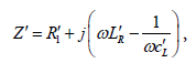 (1)
(1)
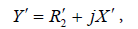 (2)
(2)
With 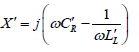 (3)
(3)
From Equation (1) and Equation(2), the complex propagation constant γ expressed in terms of per-unit-length Z` and Y`
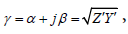 (4)
(4)
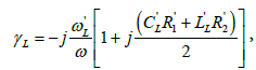
γ can be written as,
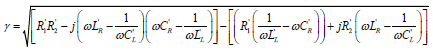 (5)
(5)
Under this condition, it can be shown that the characteristic impedance for a novel CRLH transmission lines is
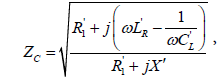 (6)
(6)
For an overview of the effects of losses in the lossy CRLH TLs (especially in the LH range), we first consider, for simplicity, the purely Left-handed TL, which is a good approximation of the lossy CRLH TLs at low frequencies.
Transmission line parameters can be presented. In this case, we consider a Purely LH TL with the following conditions  to analyze the effects of losses.
The propagation constant is given by the Floquet theorem,
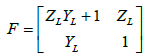 (7)
(7)
The network being reciprocal i.e. ZLYL+1 - YLZL = 1, the simplified expression leads to the dispersion relation
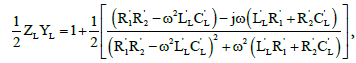 (8)
(8)
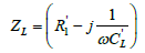
Where γL= αL+ βL (αL and βL represent the attenuation and propagation constants along the lossy LH TL). The per-unit length impedance ZL and per-unit length admittance YL in the complex domain in the case of N=1 are given. Where  and
and  are resistances, inductance, and capacitance.
 (9)
(9)
 (10)
(10)
And
 (11)
(11)
Given the particular attention to LH materials in the microwave community and their applications [7,8], several studies have demonstrated that these structures are high-pass filters and operate at low frequencies. However, at low frequencies, the ohmic and dielectric losses are relatively small in the microwave structures.
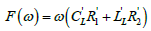
The parameters expressing the losses are reduced as follows
 (12)
(12)
 (13)
(13)
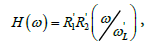
of the losses parameters one can deduce the dielectric dissipation factor
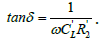 (14)
(14)
where δ is the angle of losses.
For H(ω) « F(ω) < 1 [9], consequently, the H(ω) can be neglected, and the square root of the propagation constant equation (10) can be approximated by its first-order Taylor expansion, so that
 (15)
(15)
the dispersion relation and the attenuation factor in the case of losses are obtained as follows
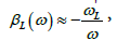 (16)
(16)
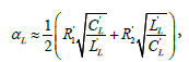 (17)
(17)
and the characteristic impedance is given by
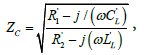 (18)
(18)
Considering equation (15) and equation (16), it appears that lossy LH TL has the same propagation constant as a lossless LH TL and the same attenuation factor as that of the classical RH TL [7]. Similarly, for CRLH TL lossy and loss less CRLH TL, including LH and RH contributions. On the other hand, the presence of the resistors in LH TL reduces the group velocity over a bandwidth and cancels out the real part of the characteristic impedance at the transition frequency.
For αL = 0, which correspond to lossless case of LH TL, i.e.  =0 the dispersion relation yield
 (19)
(19)
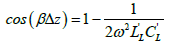
Of equation (17) this relation, arise the different properties of LH TL, namely the characteristic impedance, phase and group velocities etc. As expected from Equation (17), when ω→0,  and when
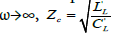
At very high frequencies, the imaginary parts of the numerator and denominator dominate over the real parts so that we have  The dynamic resistances describe the line behavior for an abruptly changing signal for which case the highest frequency components are important for obtaining the time wave form.
If lossless LH TL is considered as a cascade of networks with two identical ports, the voltages and currents can be connected on either side of the N-th unit cells by means of the matrix. However, the LH TL will be considered as a quadruple and the matrix obtained is that of equation (7). Through numerical simulations, the relationship between the propagation factor and the frequency for the different values of N units for lossless LH TL are illustrated.
Results and Discussion
In this section, in order to put into practice the theoretical formulation, by numerical simulation, the frequency responses of the dispersion relationship, the characteristic impedance and the constant factor of losses LH-TL are illustrated in Figure 2 for the values

Figure 2: Dispersion, characteristic impedance and propagation constant curves in case of purely LH TL lossy.
For small résistances, the dispersion, the propagation constant and the characteristic impedance tend to zero. But the shape curve illustrates that the lossless LH TL translates the theoretical results in case of that the dispersion of the losses and lossless are the same.
Figure 3 shows from different values of N for lossless case of purely LH TL, the relationship between the propagation constant and frequency. The different curves indicate that, when the frequency increases, the propagation constant decreases for different values of N. In the other hand, when the number of cells units N increases, the cut-off frequency decreases, which agrees with the results obtained [6], and becomes narrow on the region of the stopping band. Furthermore, in the frequency range [5-7 GHz] the slope of the dispersion pattern increases as N decreases, and a variation in the group velocity also decreases as a function of the N unit cells.

Figure 3: Propagation constant and frequency response for lossless of purely LH TL (a) N=14, (b) N=2, (c) N=1.
In Figure 4, for 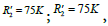 in case Figure 4(a) of dashed curve it is observed that when the values of the resistances are quite considerable, the amplitude of the S-parameter tends to zero at high frequencies, when
 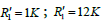 in case Figure 4(b) of dashed curve, magnitude of S-parameter reaches positive values, before decreasing to zero at the frequency 0.4 GHz, whereas for
 the strong curve decreases more rapidly when traversed by zero.
For  ((a) dashed curve) and
 strong curve), we observed that to -0.005dB, S-parameter (dashed curve) seems to be constant, then tends to zero at the frequency 0.6 GHz. However, the case where the resistances are small (strong curve), the form of S-parameter is almost identical to that of loss-less LH transmission lines.

Figure 4: (a) Simulated S-parameter of loss LH TL for  , (b) simulated S-parameter of loss LH TL for
Conclusion
In this paper we proposed lossy left-handed transmission lines. The effects of losses are caused by the presence of resistances in the LH TL. After a numerical simulation of the magnitudes that characterize the line, we observed that, the results are in agreement with the behavior of low-frequency lines in microwaves with neglected losses effects and the number of the cells units affect the propagation constant curve. These results confirm the application of Left Handed Metamaterials for microwaves and antenna design.
References
- Veselago V (1968) The electrodynamics of substances with simultaneously negative values of ε and μ. Soviet Phys Usp 10: 509-514.
- Caloz C, Sanada A, Itoh T (2004) A novel composite right/left handed directional coupler with arbitrary coupling level and broad bandwidth. IEEE Trans Microw Theory Tech 52: 980- 992.
- Zhang Y, Hu L, He S (2005) A tunable dual-broad-band branch-line coupler utilizing composite right/left-handed transmission lines. J Zhe- jiang U Sci A 6: 483- 486
- Lai A, Christophe C, Itoh T (2004) Composite right/left-handed transmission line metamaterials. IEEE Microw Mag 5: 34- 50.
- Caloz C, Okabe H, Iwai T, Itoh T (2002) Transmission line approach of left-handed (LH) materials. Proceedings of USNC/URSI National Radio science Meeting, San Antonio, USA.
- Liu TK, Tesche FM (1976) Analysis of antennas and scatterers with nonlinear loads. IEEE Trans Antennas Propaga 24: 131-139.
- Chin A, Chan KT, Huang CH, Chen C, Liang V, et al. (2003) RF passive devices on Si with excellent performance close to ideal devices designed by electro-magnetic simulation. Electron Devices Meeting, Washington, USA.
- Sabah C, Urbani F, Uckun S (2012) Bloch impedance analysis for aleft handed transmission line. J Electr Eng 63: 310-315.
- Buechler J, Kasper E, Russer P, Strohm KM (1986) Silicon high-resistivity- substrate millimeter-wave technology. IEEE Trans Micro-wave Theory Tech 34: 1516-1521