Research Article, J Comput Eng Inf Technol Vol: 5 Issue: 1
Video Stabilization and Region-of-Interest Tracking in Cardiac MRI Domain
| Gino S1*, Goitein O2*, Konen E2 and Spitzer H1 | |
| 1Department of Electrical Engineering, Tel-Aviv University, 69978, Tel Aviv, Israel | |
| 2Diagnostic Imaging Department, The Chaim Sheba Medical Center, Tel Hashomer, affiliated to Sackler School of Medicine, Tel Aviv University, Israel | |
| Corresponding author : Shahar Gino Department of Electrical Engineering, Tel-Aviv University, 69978, Tel Aviv, Israel Tel: +972-3-6409017, +972-3-5302530 Fax: +972-3-6407939 E-mail: shaharg8@mail.tau.ac.il, sgino209@gmail.com |
|
| *This author is an equal contributor: Orly Goitein Diagnostic Imaging Department, The Chaim Sheba Medical Center, Tel Hashomer, affiliated to Sackler School of Medicine, Tel Aviv University, Israel E-mail: Orly.Goitein@sheba.health.gov.il |
|
| Received: December 04, 2015 Accepted: January 13, 2016 Published: January 20, 2016 | |
| Citation: Gino S, Goitein O, Konen E, Spitzer H (2016) Video Stabilization and Region-of-Interest Tracking in Cardiac MRI Domain. J Comput Eng Inf Technol 5:1. doi:10.4172/2324-9307.1000140 |
Abstract
Video Stabilization and Region-of-Interest Tracking in Cardiac MRI Domain
Stabilizing Cardiac-MRI (CMRI) sequences, such as the myocardial first pass perfusion, is expected to allow a significant improvement in medical diagnosis. Such stabilization is crucially required due to the diaphragm motion, throughout the respiratory and cardiac cycles. The above challenge is also valid generally in computervision for video-stabilization and region-of-interest (ROI) tracking of non-rigid objects. We suggest a novel algorithm for CMRI tracking and stabilization, which is inspired by cortical mechanisms of the human visual system (HVS), for both edge and region pathways. The algorithm adaptively weights these pathways according to the ROI state. The ROI is tracked through a two-stage pipeline; a coarseengine first extracts a linear approximation of the motion, followed by a fine-engine, which allows edge deformation. The ROI motion is then estimated by common linear-approximation for stabilization. The Video-stabilization is obtained by solving the ROI-tracking problem, while keeping its initial position fixed. The proposed automatic algorithm was tested on several CMRI videos. The stabilization quality was assessed using tools based on Inter-Frame-Similarity (ITF) and Structural Similarity (SSIM) metrics. In addition, the results were clinically rated on a 1-5 scale by two radiologists. Both the engineering and clinical assessments were used in comparing our results with state of the art competitor methods, wherein our results were generally favored over the competitors (7 of 10 cases, 1 case is controversial, i.e. preferred clinically only). Our algorithm manages to stabilize perfusion CMRI slice for long burst of frames, which indicates the potential for allowing a better medical diagnosis.
Keywords: Cardiac MRI; CMRI; ROI tracking; Video processing; Medical vide; Video stabilization; Perfusion
Keywords |
|
| Cardiac MRI; CMRI; ROI tracking; Video processing; Medical vide; Video stabilization; Perfusion | |
Introduction |
|
| Video-stabilization and Region-Of-Interest (ROI) tracking are well-known problems in computer-vision, with many practical applications such as surveillance, monitoring, motion-estimation and etc. [1-3]. These applications become even more challenging for gray videos, in which separating ROI from its background, as well as using common computer-vision similarities and features, are less accessible [4]. The reason for this is probably derived mainly from the fact that most of studies on tracking and stabilization made an effort on the most common videos that are with color. Most of the medical images (including CMRI), however, are consisted of achromatic images. The tracked objects in medical media, such as in CMRI, often have a fast-varying texture, smooth edges and a deformable contour; these unique conditions pose the tracking problem again in an unusual manner. A good example for such a challenging video is Perfusion (a.k.a. TCShort- Axis, see Figure 1) sequence of Cardiac-MRI (CMRI), which is non-invasive tool to assess myocardial ischemia [5,6]. This type of clinical examination is influenced by the diaphragm and the cardiac motion throughout the respiratory and cardiac cycles. This complex motion results a very noisy and trembling video. | |
| Figure 1: Several TC-Short-Axis CMRI frames, which demonstrate the fast varying texture and contour-shape of the heart. | |
| ROI-tracking can generally be divided into 2 subcategories: Edge- Based and Region-Based trackers [7]. Tracking by edge-base method assumes that the object, which has to be segmented, has its own distinguished boundary in the image. This boundary can be detected as prominent edge. Tracking by region-based method assumes that the region of the object in the image has a distinguished different statistic in some feature space in comparison to its surrounding regions. Several solution approaches were suggested over the past years for the object-tracking problem [8-10], each brings its own advantages, but also suffers from its own drawbacks. | |
| Many of the common methods assume prominent features such as chromatic characteristics, sharp contour, constant brightness, motion’s component, unique texture, and etc. [11-13]. It appears that some of the common assumptions are less suitable for gray-scene, as appeared often in medical video, such as in cardiac MRI perfusion. | |
| Previous medical relevant studies which relate to tracking and/or stabilizing cardiac videos focus on the left ventricle. Some apply video processing methods [14-16], while other are based on designated motion-model which are developed due to theoretical assumptions on the heart motion [17,18]. Obtaining stabilization requires compensation of the heart’s motion as a whole. Registration and tracking of the left-ventricle only, cannot accurately apply on the overall heart motion, and therefore not perfectly suitable for solving the stabilization problem. | |
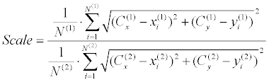
| There are additional recent studies which try to model the motion of the heart as a whole [19-21]. The motion of the heart can be notated as a combination of translation, rotation, scale and nonrigid deformations (Equation 1). Only few previous studies include all of these four motion components [22-24], while most of the previous studies only include part of the components [25-38]. The various studies also differ by their core strategy in modeling the heart motion. Many recent studies adopted a multi-resolution strategy [22,26,27,29], while others have implemented a coarse (rigid) to fine (elastic) approach [23,36]. Other studies tried to obtain registration through different frameworks such as ICA [32,33], graph-cuts [31] and level-set [35]. Most of the previous work relied on intensity information, while few other works suggested a solution in the wavelet and frequency domains. An additional major differentiator, which affects both registration result and stabilization evaluation, is the similarity measure that was applied by each study. Most recent studies have followed the MSE measure [22,25,26,28,38], but few other studies have followed other similarity measures such as MI [29,37], Bhattacharya [31], MDL [24] and NGF [36]. | |
| It is worth mentioning that most of these studies refer to the problem as a registration problem rather than a stabilization problem. By that, it is implicitly assumed that stabilization might easily be obtained once registration is met. This assumption led most studies to rely on manual registration as a ground-truth, which is not sufficiently exact, mainly due to the inaccurate delineation. Moreover, only few previous works dealt with the question of stabilization evaluation. Most of these works evaluated the perceived stabilization in context of absolute-motion [24-26,28,38], although few other recent works adopted statistical approaches [23,36] or based their evaluation on left-ventricle registration [32,33,35]. It appears that most of the above existing works suffer from few deficiencies – some works rely on prior information such as an anatomical model [22,31] or prior-training [24], others supports translation only [25] and does not support nonrigid deformations [28,29,32,33,36-38]. | |
| The goal of this study is to develop a unique algorithm, which is based on components of visual adaptation mechanisms, in order to cope with the challenging tracking and stabilization in cardiac MRI perfusion. | |
| Note: From that point and on the term ‘CMRI video’ will be used in the context of TC-Short-Axis series of a CMRI video. | |
Method |
|
| Main rational | |
| We suggest a novel algorithm, which aims to stabilize CMRI videos according to a given ROI. The algorithm mainly consists of 3 parts: tracker, motion-estimator and motion compensator. Videostabilization is obtained by solving the ROI-tracking problem while keeping its initial position fixed. The ROI motion is then estimated by a ‘linear-approximation’ (translation, rotation, scale), and is used for stabilization. The motion approximation terms such, even though a translation component performs the transformation non-linearly. However, from now on we will term this approximation ‘linear’. Our algorithm combines information from both edge and region domains and adaptively weights them according to ROI current state. It is autonomous, self-adapting and requires no user-interference. It is intended to be robust to video type and highly-sensitive to objects motion. Moreover, it is also supposed to handle occlusions and deformations. | |
| Initial guidelines: In order to efficiently apply the above stabilization approach (ROI tracking, motion estimation, motion compensation), it’s required to characterize the heart (ROI) motion. Several observations can be noticed when viewing a CMRI video and focusing on heart as a region of interest: | |
| For some of the frames the heart has more prominent region characteristics (e.g. left and right ventricles). | |
| For other frames the heart has a more distinguishable occluding contour. It is often appears as not a continuous contour, while some of its fragments are more prominent than the others. | |
| Heart motion is complex due to different elements that contribute to the motion, among them are: | |
| Heart natural motion (heartbeats). | |
| Internal motion of inner organs and tissues parts and perfusion fluid motion within the heart. | |
| Global motion due to patient respiration [39]. | |
| The first two motion elements should be preserved for radiological analysis, while the third one disturbs the diagnosis and therefore should be removed. | |
| The first motion element (a) is modeled as a scaling only operation (contraction and relaxation), in addition to a small nonlinear deformation (cardiac cycle). The second motion element (b) is considered as a varying texture. This consideration makes the CMRI perfusion stabilization even harder since the internal-motion is not common for all organs and tissues parts. The third motion element is modeled as a translation in addition to rotation. The total motion of the heart is thereby could be modeled as following (Equation 1): | |
| where |
|
| The stabilization goal is defined as keeping the heart (ROI) at a static position over all frames (i.e. its motion should not be interfered with the surrounding organs). The “static position” refers to location and orientation but not to scale operation (Equation 2 – Stable [•] operator). | |
| CMRI stabilization is considered a difficult challenge in computervision, due to the fast-varying texture, the smooth and unclear edges and the deformable contour (Introduction; [1-3]). Hence, observing a CMRI video immediately raises the question of how humans are capable of tracking the fast varying heart across the frames. It could be that human vision system (HVS) adaptively weights the frame’s information [40] according to possible change in heart appearance at each frame. The heart has a clearer interior pattern at several frames, while at other frames it has a clearer occluding contour. | |
| An additional observation is that the interior movement inside the heart does not confuse the HVS, in the manner of heart boundaries determination. It could be that the human visual-system learns, onthe- fly, which of the information is more reliable and which one is less [41]. It is also possible that the visual-system analyzes the scene through several channels simultaneously, such as brightness and spacial frequency. The HVS might perform this multiplechannels computation, in order to take advantage of all the available information pathways [42]. Our model also utilizes the neuronal receptive fields (RF), which perform oriented edge detection, through mainly the RF of simple cells in areas V1 and V2 [43]. | |
| The goal of this algorithm is stabilizing through tracking the heart at each frame, then analyzing and compensating its motion comparing to first-frame position. Consequently, the stabilization problem is actually turns into a tracking problem. | |
| Data acquisition | |
| Short axis vies of the heart were acquired using a 1.5 T ME system (Signa HDxt ver-15, GE Healthcare, Milwaukee, WI, USA) using dedicated 8 channel cardiac coil. For perfusion series a fast gradient echo sequence was used (time course, GE Healthcare, Milwaukee, WI, USA). Flip angel=20, echo time=1.3 msec, repetition time=2.9 msec, FOV=40×36, slice thickness=10 mm, gap=0 mm, bandwidth=83.3 Khz, matrix size=128×96, ECG triggered at auto-heart rate adjusting to the patient heart rate. Bolus intravenous injection 0.01 mmole/Kg (rate 5 ml/sec) Gd-DTPA (Magnetol, Soreq pharmaceuticals, Israel) followed by a 20 ml saline flush. | |
| Main scheme | |
| The algorithm has 2 inputs: a CMRI video which has to be stabilized and an initial ROI marking, while it generates a stabilized video for an output. Figure 2 depicts the algorithm’s main-scheme. Each input frame is first split into 2 separated feature domains – brightness and texture features (Lateral Facilitation, [44]). Brightness channel is then split again into 2 additional channels – edge and region based (“Channels Generation”, Figure 2). We develop a linear-contour generator (“Coarse Engine”, CE) which manipulates (rotation, scale, offset) previous-frame’s contour, in order to find the best candidate for the current frame. This is done iteratively over the frames. | |
| Figure 2: Top-view of the algorithm scheme. | |
| Each such manipulation (“trial”) obtains a weighted score, which is written into a designated scoreboard. The derived contour, which gets highest score, optionally enters a nonlinear contour generator (“Fine Engine”, FE). The FE allows deformations and a higher resolution than the CE, for motion estimation. The algorithm flow is controlled automatically by an adaptive controller, which takes into accounts several notations such as weighting over channels (region/ edge), features (based on contour brightness) and features’ segments. | |
| Our algorithm assumes small inter-frame changes, both linear and non-linear. Linear changes should be remained within the CE search-region. Non-linear changes should be within the FE searchregion. These can be considered as the limitation of our algorithm. The following sub-sections explain the exact algorithm flow while providing all details, based on Figure 2. | |
| Contour-adjustment phase (ROI tracker) | |
| Each input frame first enters a ROI-tracker (Contour Adjustment module), which adjusts the ROI marking from previous frame for fitting the ROI location in the current frame. The ROI tracker receives 2 inputs – current frame and ROI marking of previous frame. It generates ROI marking for the current frame, as its output. | |
| Coarse engine: The main module of the ROI-Tracker is termed “Coarse-Engine”. It is a linear generator that runs an exhaustive search for finding the best contour candidate in current frame. The search covers different domains: rotations, scales and offsets of previous-frame contour (Equation 3). Hough sub-engine (Figure 2) is used for injecting a-priory information (prior) into the lineargenerator. It seeks for prominent lines in the current frame (in a certain window) and adds their relative rotations into the lineargenerator search-space. | |
| The Hough Sub-Engine (HSE) acts as a generic option for injecting priors for the algorithm. It cannot deteriorate the stabilization results, currenteven if the prior is wrong, since the HSE only expands the searchspace of the CE by adding more candidates to be examined. Thus the HSE can only improve the tracking precision. | |
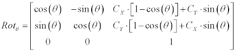
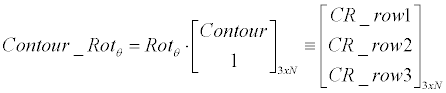
| Linear generator: Equation 3 demonstrates how the linearcontour- generator manipulates the input contour over a given rotation (�?�?), scale (S) and offset ([dX, dY ]). The input contour is represented here as |
|
 |
|
 |
|
 |
|
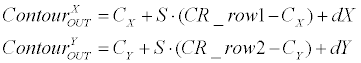 (3) (3) |
|
| Scoreboard: The linear-contour-generator’s output is used for sampling each frame in a 2 separated dimensions: Shape- Analysis (SA, contour channel) and Inter-Frames-Similarity (IFS, region channel). Each of these 2 dimensions yields an independent score, which is written in a designated scoreboard, as schematically shown in Figure 3. | |
| Figure 3: Illustration of the scoreboard (SB) used by the CE. Each line in the scoreboard presents a single contour candidate, which obtained using linear manipulations over previous frame ROI marking (Equation 3). | |
| The main motivation for separating the sampling into Contour and Region channels came from a simple observation that general ROIs can usually be termed as either “edge” or “region” ROIs [45]. Contour pathways contain ROIs, which enfold most of the unique information on their occluding boundary, while region channels contain ROIs that are mostly specialized by their inner area. This separation allows the flexibility of giving different weights for region/ contour channels during later adaptive processing, according to the ROI manner. | |
| Shape-Analysis phase is done using filters that are inspired by simple cell’s RF at HVS [46]. The first stage, of this phase, is generating scaled-in (90%) and scaled-out (%110) spatially versions of the candidate contour, as demonstrated in Figure 4. | |
| Figure 4: Scaled-in and scaled-out versions (red dotted) of the candidate contour (orange solid). Image is sampled according to these three scales and shape score is then calculated using HVS-like filters (Figure 5). | |
| In the second stage of this phase, each pixel of the original contour and its scaled-in and scaled-out versions is replaced with the ‘importancesampling’ |
|
| where |
|
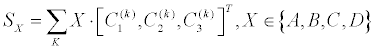
| The score of shape analysis is then calculated, Equation 5 | |
 (5) (5) |
|
| Where the summation SX is an intermediate score which is obtained using 4 HVS-inspired filters, separately for feature k . WX is their corresponding weighting factor (Figure 5). C1 is the scaled-in contour, C2 is the original contour and C3 is the scaled-out contour (Figure 4, all after important sampling). The A B C and D present the four chosen spatial filters (Figure 5), which have been inspired by HVS. It has been applied mathematically by 1x3 vectors, which are expressed as [1,0,0] [1,0,1] [0,1,1] [1,1,1] and termed as A,B,C,D correspondingly (Figure 5). Each of such intermediate score is practically obtained by the inner-product of the HVS-filters with the 3x1 contour vector, |
|
| Figure 5: HVS-inspired filters and their corresponding weights (right side), used for shape analysis phase in score calculation (Equation 5). The plus and minus signs represent the sensitivity to bright and dark zones, respectively, as commonly used for receptive fields. These filters are applied on the image samples (Figure 4) in perpendicular-direction to the contour edge. | |
| The motivation of using such a strategy is to credit features that are probably located at the edges (A) or “tunnels” (B), and also to punish features that are located outside of the edge (C), or inside of it (D). This approach leads to a maximum score for the contour candidate whose features best enfold the ROI. | |
| Inter-Frame-Similarity (termed as Region-Channel phase in the Coarse-Engine, Figure 2) is done by checking how similar currenteven frame region in comparison to previous-frame region. In this context, region refers to the interior of the contour. The current frame needs to be registered to previous frame coordination before the comparison between the two is done. Using linear estimation, based on last iteration solution, performs it. Several similarity measures were examined for this purpose: Sum of Squared Differences (SSD, MSE based [46]), Multi-scale Structural Similarity (MSSIM [47]) and Mutual Information (MI [48]). The similarity between the 2 regions is analyzed using a weighting-mask based on a unique oriented multi scale filter, termed Lateral Facilitation or simply LF (Main Scheme; [44]), which has been recently computationally developed for Lateral-Facilitation HVS phenomenon [49]. Such a filter enables enhancing different textures by their edges. The motivation for that is to enhance lines and gaps between the lines that the visual system leads us to perceive them as real contours or continuous fragment in a given texture. This leads also to enhancement of reliability of features, which are part of lines in the image and therefore might be representing further important information. IFS score calculation is described in Equation 6. | |
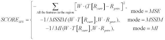 (6) (6) |
|
| where W presents the LF weighting mask (calculated for current frame ROI), Rprev presents the previous-frame region matrix and T [RCurr] presents the current-frame region matrix after registration (T [•]). MSSIM and MI represent ordinary similarity operators for MSSIM and for MI, respectively [47,48]. W, Rprev, Rcurr are matrices with the region’s dimension. | |
| Best linear candidate is chosen using a simple statistical analysis of the scoreboard (Figure 3). Scores weighting of both contour (SA) and region (IFS) channels is done on-the-fly according to the ‘scorings variance’. Hereby ‘scoring variance’ refers to the scores subtraction over four best sequential scorings, for each scoring-type (SA & IFS). We assume that a good scoring-type (which is highly weighted) can obtain a better separation of the ROI from its background. | |
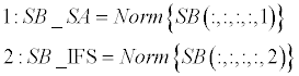
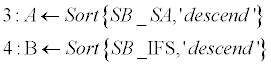
| High variance implies that the scoring-type can be “trusted”, while low variance suggests that scoring-type might be less suitable for current frame. Algorithm-1 pseudo-code suggests the way of extracting the best candidate (termed as “winner”) from the scoreboard, according to the above rational. This algorithm is generic and can be useful for a general scenario of which several candidates have multiple scores. In such a case there is a challenge of how to select best candidate. | |
| Sorting phase (lines 1-4): SB_SA and SB_IFS contain normalized scoreboards for Shape-Analysis and for Inter- Frame-Similarity, respectively. These two scoreboards are then sorted in a descending order (A, B). Normalization is required since the two scoreboards might be in different scales and aimed to be merged in following stage. Norm (·) stands for a standard [0,1] normalization operator, and Sort (·,’descend’) stands for a standard sorting in a descendingorder operator. | |
| Weighting phase (lines 5-6): W presents a weighting vector for the SB_SA and the SB_IFS scoreboards. It consists of the differences of the first 4-order elements in both scoreboards (‘variance’). A unified scoreboard is than generated by merging SB_SA and SB_IFA according to the calculated weighting vector (W). | |
 |
|
 |
|
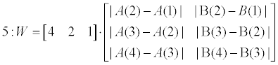 |
|
 |
|
| Algorithm 1: ScoreBoard analysis for extracting best parameters. | |
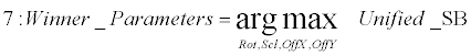
| Extraction phase (lines 7): The parameters which best approximate the linear transformation over the two sequential frames are thereby extracted as the arguments that correspond with the maximal score in the unified scoreboard. | |
| Fine engine: The Coarse-Engine suffers from two main drawbacks – it doesn’t support non-linear deformations and it searches for the best candidate in a discrete domain. At that stage, therefore, the best candidate (‘CE Winner’) might conditionally enter the Fine-Engine (FE) which adds a nonlinear flexibility and corrects errors from CE stage. | |
| The FE processing stage consists of an innovative technique termed “Shrink-And-Expand”. The intuition behind this approach is that the real ROI boundaries at current frame can be determined by a small variation from the ‘CE winner’ contour, which acts as a best linear predictor. During this stage the real ROI position is searched from the shrink version of the ‘CE winner’ contour to its expanded version (Figure 6). | |
| Figure 6: Illustration of “Shrink-And-Expand” approach which is implemented in FE stage (Algorithm 2). The ROI boundaries at the current frame are marked with bold red line, the CE-Winner is marked with blue dashed line, the shrunk and the expanded contours are marked with green dashed-dotted line and the traveling paths are marked with gray arrows. | |
| Following are the Shrink-And-Expand steps (Algorithm-2): | |
| 1. Generate shrunk and expanded versions of the CEwinner contour, e.g. 90% and 110% of the CE winner, correspondingly (green dashed-dotted lines, Figure 6). | |
| 2. Connect matching points across shrunk and expanded contours with straight paths (gray arrows in Figure 6). | |
| 3. Sample current frame along the shrink-to-expand paths, and smooth it using standard average-filter (LPF). | |
| 4. Generate a deformation probability, P(x), based on features weights (Equation 7): | |
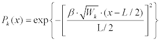 (7) (7) |
|
| Where |
|
| 5. For each feature do: | |
| Find highest edges over each path (gradient peaks). | |
| Find brightness peaks over each path. | |
| Find previous neighbor deformation/reallocation: | |
| Note that the deformation-probability from step 4 is used as a masking weight for each of these criterions findings, separately. | |
| 6. Reallocate points as a soft decision based on step 5. | |
| 7. Smooth across the features at the features plane. | |
| 8. Interpolate across the features at the features plane. | |
| Algorithm 2: Shrink-And-Expand algorithm for Fine-Engine stage | |
| The Shrink-And-Expand is a computational fast tool that respects orientations, since deformations are searched perpendicular to the linear prediction (CE winner), Figure 6. The Fine-Engine stage, applies this specific approach, which can be considered as an edgedetection phase in a highly textured domain. The Shrink-And-Expand approach was designed to handle texture under the assumption that the highest peaks in brightness and edges are due to the real ROI boundaries (Algorithm-2, 5). A prominent texture adjacent to the CE-winner might generate outliers, and thereby causes a wrong contour adjustment. Therefore a temporal-filtering is used in order to smooth textural interior patches (Figure 7). The temporal-filtering is done over 3 sequential frames and assumes only texture varies over that temporal window, while real ROI boundaries remains. This filter uses feedback from last two previous frames, in order to initiate the filtering over the same ROI position. | |
| Figure 7: Illustration of the Temporal-Filtering, which is implemented in FE stage. This processing stage is done in order to smooth prominent texture, which might lead to a wrong edge-detection during “Shrink-And-Expand” flow (Algorithm 2). The figure demonstrates the attenuation of the interior texture strength of the ROI, while maintaining its external boundaries. | |
| Motion-estimation phase | |
| The ROI-tracker (CA) result enters a Motion-Estimation (ME) phase (Figure 2). The ME receives 2 contours as input – ROI positions at current frame and at previous frame. It outputs an approximation of best linear affine transformation, which describes the transition between the two contours. These motion parameters are required by the next processing phase (stabilizer) for motion compensation. Note that in the case that FE was deprecated in CA phase, then the ME outputs will be equal to CE-winner parameters. | |
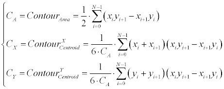
| The first stage is translation estimation, which is performed according to the centroids offset over the two contours (ME inputs). The centroid for a N -degree closed polygon is calculated according to Equation 8. | |
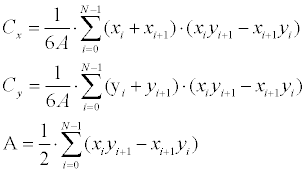 (8) (8) |
|
| Where the polygon is represented here as |
|
| The second stage is rotation estimation, which is performed using an exhaustive search over π radians with a half radian resolution. Region Intersection (RI) similarity [50] is used for choosing the best rotation candidate (Figure 8). Each rotation-candidate contour gets a RI score (Equation 9), while the estimated rotation is determined according to the highest score. RI was found most appropriate for our case, after a trial and error procedure, which included examination of several other similarity measurements such as MSE, SSIM, and etc. Finally, scale is extracted as the ratio between the mean distances from each centroid to its occluding boundaries (Equation 10). | |
| Figure 8: Region Intersection (RI) similarity is used for ME (Figure 2) rotation estimation. ‘A’ (red) and ‘B’ (blue) presents two contours. A “good” candidate for a rotation transformation over the two, is one with a high true-positive (TP, white) area and low false areas (FP+FN, colored). | |
 (10) (10) |
|
| Stabilization phase | |
| The final processing stage gets the current frame and the estimated motion parameters (results of ME phase) as inputs, and thus generates a stabilized version of the frame (Figure 2). It is calculated by compensating the estimated motion. Motion compensation is done by an inverse affine transformation, which is based on the translation and rotation estimations from ME phase (section-D). Scale component is not compensated, since all scale changes are assumed to be derived from heart natural motion (heartbeats), which should be maintained. | |
Results |
|
| Clinical evaluation of the algorithm | |
| We acquired 3 time sequences of TC-short-axis CMRI images from 10 patients. Each sequence contains ~40 frames (images from different depths). All of the CMRI videos, and the corresponding diagnoses, have been received from Sheba medical center. The participant patients, which are all adults, were informed and agreed to take part in this study, while keeping their identity anonymous. We compare here several state-of-art algorithms to our algorithm results – some of them are leading commercial tools, while others are known algorithms that we’ve implemented. | |
| Following are the tested algorithms and tools, which have been tried for each patient’s CMRI videos that are marked with ‘A’ to ‘H’: | |
| A = Input video (“original”) | |
| B = Lucas-Kanada-Tomasi (LKT) [51] | |
| C = Template Matching (TM) [52] | |
| D = Adobe Premiere Pro CC [53] | |
| E = YouTube stabilizer [54] | |
| F = VirtualDub Deshaker 3.0 [55] | |
| G = Our algorithm using MSE similarity for IFS (Equation 6) | |
| H = Our algorithm using MSSIM similarity for IFS (Equation 6) | |
| Algorithm’s parameters | |
| Contour resolution: 50 features, window-size 11x11. | |
| CE-engine (Figure 2) search-space: | |
| 3 Rotation values: 0, ± π / 32. | |
| 3 scale value: 0.95,1.00,1.05 . | |
| 9 translation values: 0, ± 1, ± 2, ± 3, ± 4 . | |
| → Number of iterations per frame: 32 • 92 . | |
| • FE-engine (Figure 2) search-space: | |
| - Shrink factor: 0.8, Expand factor: 1.2. | |
| Contour resolution affects both CE and FE pipes. More features and a smaller spacial window (Equation 4) yields a higher resolution, but in trade of lower resistance to noise (less smooth). A larger CE search-space increases the tracking precision, and might also lead to a more pronounce ‘winner’, however it increases algorithm complexity (runtime). A larger FE search-space can allow a better support for non-linearity and deformations, but it may also lead to local outliers on the adjusted contour. | |
| Stabilization assessment | |
| Assessing the stabilization results is a critic requirement for comparing our algorithm with other methods (A-H in: III-A). The assessment methods can be generally divided into 2 types: clinical assessment and engineering assessment. The first type suggests assessing the stabilization results through radiologist diagnosis, while the second type does not require any human interference and relies on similarity measure selection. | |
| Clinical assessment: The clinical assessment consists of 2 expert CMRI radiologists from Sheba medical center (O.G. and E.K., with a clinical experience of 8 and 11 years respectively in CMR), which were requested to review the 10 different videos for each patient. Each CMRI patient’s video, which was compared over A-H methods, was introduced to the radiologists for clinical evaluation in a single 2x4 windows matrix presentation, termed ‘case’ (Figure 9). The radiologists’ evaluation was initiated after a random shuffling of the video windows (bottom-right button in Figure 9). The radiologists were then asked to rate the different windows from 1 (less stable) to 5 (most stable). | |
| Figure 9: The method of clinical assessment of our algorithm and its competitor algorithms. The Clinical assessment platform (web-based) consists of 10-different clinical cases (which represents videos of different patients) and 2x4 windows-matrix (randomly shuffled), which corresponds to 8 different filters (A-H in III-A). The viewer was requested to rank each window from 1 (least stable) to 5 (most stable). The red cross-mark within each window is static and appears only for enabling the radiologist a better stabilization assessment. | |
| Engineering assessment: A good engineering assessment approach can be acting as an automatic tool for determine whether our algorithm was able to make any stabilization improvement for the input video and in what scale. Thus, the engineering assessment was used to compare our algorithm to the input only, regardless to other competitors. Various types of similarity measures for engineering assessment have been suggested in the literature. The most commonly used types are ITF, GTF, PSNR and SSIM [46-48]. | |
| The stabilization assessment of current study was finally done using both strategies – clinical and engineering. Each stabilization result was thus introduced to CMRI radiologists and got their clinical opinion (using a 5-points scale, where 1=least stable and 5=most stable). In addition, each such case obtained engineering scores according to the ITF and the SSIM stability gains (Equation 11). | |
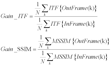 (11) (11) |
|
| Where InFrame and OutFrame refer for the original video and the stabilized video respectively. ITF {•} was implemented as PSNR between successive frames (Equation 12), while MSSIM {•} was implemented according to [56]. | |
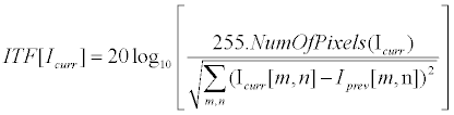 (12) (12) |
|
| Here |
|
| Following figure (Figure 10) describes the mean ITF and the mean SSIM of the input videos, which have been termed here as their engineering “native stabilization”. Videos that obtained a higher value are natively more stable (Equation 11). | |
| Figure 10: Mean ITF and Mean SSIM of the input cases, which can be referred as their engineering native stabilization. Each bar corresponds to a different clinical case. | |
| It can be observed that: | |
| Cases #3, #5 and #6 are most natively stable. | |
| Moreover, these 2 similarity measures are not fully correlated. | |
| In addition, SSIM appears to be a more sensitive measure, as the different input cases are much more distinguishable. These observations are further discusses in section 6 below. | |
| Stabilization results | |
| This section provides the core experimental results of our study. A thorough discussion for these results is followed in section 6. Following figure describes the clinical-assessment results, as described in section 5.3 above (Figure 11): | |
| It can be observed that our algorithm results (either MSE or SSIM for IFS, as described in section-C-Scoreboard) were preferred by both radiologists for all cases, except #5 and #6. | |
| Figure 11: Clinical assessment results of our algorithm and its competitor algorithms. These results are based on 2 radiologists’ rankings in a 1 to 5 scale. The horizontal axis lists the 10 different cases while the vertical axis shows the retrieved rankings. Each color represents a different method, includes original input, our results and state-of-art competitors. | |
| Figure 12 below describes the engineering stability gains (Equation 11), using either MSE or SSIM as similarity measure for the ITF phase: | |
| Figure 12: Engineering assessment results based on ITF and SSIM similarity measures. The assessment of our algorithm results are compared with original input. | |
| It can be observed that our algorithm results were engineering preferred (either MSE or SSIM for IFS) for all cases except #5, #6 and #10. Average ITF improvement is +0.79 ± 1.57 dB for MSE and +0.90 ± 1.51 dB for SSIM, while average SSIM improvement is +0.017 ± 0.036 for MSE and +0.020 ± 0.035 for SSIM (average refers all 10 cases). However the preference is not statistically significant for all cases (e.g. t-test). In addition, both methods appear to be correlated for all cases, except for case #5 at which our results were only preferred by the ITF approach (Figure 12). It could be that the reason for this is the high native stability of case #5, according to SSIM criteria (Figure 11, bottom). | |
| The Coarse-Engine can be configured to use a specific similarity measure (Equation 6). Our preliminary results were focuses on MSE and SSIM. It appears that these two configurations gave similar results for both the engineering and the clinical assessments (Figures 11 and 12). It appears that the MSE and SSIM are more distinguishable in the clinical assessment (Figures 11), but still there is no prominent advantage for neither of the two measures. | |
| From complexity perspective, it can be applied that the CE takes most of the time and space. Each frame requires O(R*S*X*Y) iterations, and space is mainly for storing the image itself and the scoreboard. Note that image size affects only the space-complexity and not runtime. Runtime mainly affected by the CE search-space (contour resolution is also negligible compared with CE). | |
Discussion |
|
| Our algorithm, which has been partly inspired by the human visual system, succeeded to perform a stabilization of CMRI TC-Short-Axis. To perform such stabilization we propose a new regionedge combined ROI-tracking approach, based on several unique components. One of them is for region weight function (“W” in Equation 6), which has been applied through a visual system mechanism termed “Lateral-Facilitation effect” [44]. This function was implied in the Region channel (similarity) of the Coarse-Engine (Section-5.4, Figure 2). Additional unique component is related to the detection of the edge location, through similarity to cortical receptive-fields like filters (Figure 5). This function was implied in the Contour channel (shape-analysis) of the Coarse-Engine (Section-5.4, Figure 2). The shrink and expand novel method (Figure 6) suggests a delicate matching and compensates for non-linearity. This method was implied in the Fine-Engine (Section-5.4, Figure 2). | |
| Most of the previous studies in this field refer to the issue of CMRI stabilization as a registration problem rather than a stabilization problem (Section 4.1). By that, it is implicitly assumed that stabilization might easily be obtained once registration is met. This assumption led most studies to rely on manual registration as a ground-truth. These studies probably followed the common ground-truth method for registration, which is manual delineation [28,31,33,34]. However, manual delineation might lead to inaccuracies in stabilization process of medical videos, since the boundaries of the ROI are not sharp and not homogenous in these images. The ROI in each frame in these videos has no prominent boundaries, which makes its registration to be often not well defined. As a result, any manual attempt to obtain an ideal registration (“exact delineation”) as a ground-truth reference might trigger wrong steps in stabilization in medical imaging. | |
| Moreover, only few previous studies dealt with the issue of stabilization evaluation. Most of these studies evaluated the perceived stabilization in the context of absolute-motion [24-26,28,38], although few other recent works adopted statistical approaches [23,36]. MSSIM was already previously preferred in such cases where human judgment is required, as it appears to better fit the human visual perception [47]. Our study relies on either ITF or MSSIM as a similarity measure for stabilization method. | |
| Few previous studies, which dealt with the question of stabilization evaluation, have based their evaluation on left-ventricle registration [32,33,35]. Obtaining stabilization for the whole heart, based on the left-ventricle as a local ROI, could have possibly worked if the left-ventricle had prominent boundaries and if the heart was rigid. However, it is not the case for the perfusion CMRI. Ideal-registration for the left-ventricle is not injective, since different radiologist experts might come with slightly different delineations. This might lead to stabilization errors. In addition, since the heart is not perfectly rigid, it is not necessarily accurate to conclude a linear dependency between the left-ventricle’s motion and the whole heart’s motion. | |
| Several previous studies dealt with cardiac segmentation and left-ventricle tracking [17-21,44], but none seem to be dealing with whole heart tracking such as in TC-Short-Axis perfusion (section-3). Hence, we had to compare our algorithm results with several stateof- art algorithms results (A-F in: IIIA), which can also cope with non-rigid objects. Some of them are leading commercial tools, while others are known algorithms that we’ve implemented by ourselves. Although our algorithm didn’t win in all cases, none of the above competitor algorithms has managed to ‘win’ in all of the tested cases either. Moreover, our algorithm reached highest success rate in this context (~80%). | |
| The preliminary results of our study are quite encouraging in the sense of object tracking and video-stabilization. The engineering and the clinical results suggest to be highly correlated. For both, our algorithm results were preferred in all cases #1-#9, except for cases #5 and #6. In that context, Case #10 is controversial, since our algorithm was only clinically preferred, but not engineering (Figures 11 and 12). | |
| The question why our algorithm didn’t succeed to yield better results in cases #5 and #6 (Figures 11 and 12) has to be discussed. We suggest that the reason for this might be derived from the high natively stable nature of these videos (Figure 10). In such a case, the algorithm improvement falls within the discrete noise level, i.e. CE winner is not pronounced sufficiently in the scoreboard. | |
| Case #10 appears more stable after the algorithm application, at least according to the clinical assessment (Figure 12). However, it didn’t win the engineering assessment (Figure 11). This diversity in the results can imply that the engineering assessment not always correlates with the visual impression and the clinical results. The reason for the low ITF and SSIM scores might be due to the fast varying texture of the input video. Thus the differences between sequential frames are not small for this case, and might cause a bias for the ITF and SSIM measurements. Further adaptive weighting techniques, such as the LF mask, can be developed in the future, and be an integrated to the ITF and SSIM measurements. Such development has a potential to obtain a better engineering measurements. | |
| The most novel components of our algorithm are probably the Scoreboard analysis (Algorithm-1) and the FE Shrink-and- Expand scheme (Algorithm-2). We’ve utilized a generic approach for extracting a ‘winner’ from the Scoreboard. The main challenge was to weight the non-scale grades (e.g. region and edge). This method can probably generally be applied for any winner-selection case, which involves several candidates, where each has non-scaled grades. | |
| The FE approach can also be extracted for general usage of edge-detection and non-linear tracker. In this context, it should be mentioned that for many medical applications, there is no real need for a continuous stabilizer. That means that there is only a requirement for stabilizing a specific single depth-slice (without ‘jumps’). In such applications, we can drop the usage of the FE, and only use the CE pipe. This may be considered as a private-case of the general challenge, which our algorithm was built to cope with. | |
| Our study has succeeded to stabilize the Cardiac-MRI (CMRI) perfusion sequence, aka TC-Short-Axis, by tracking and compensating the heart motion. The success of our algorithm appears more prominent in light of having stabilization and tracking with long burst of frames. This should assist cardiac radiologists with conducting their medical diagnosis. In addition, our study can also be applied for additional issues in Computer-Vision, particularly for such that deal with tracking in a fast-varying textured environments, even achromatic [56,57]. | |
Competing Interests |
|
| The authors declare that they have no competing interests. | |
Authors’ Contributions |
|
| SG and HS participated in the design of the study and performed the statistical analysis. OG and EK carried out the clinical aspects of providing a medical imaging database and corresponding clinical knowledge. | |
Acknowledgments |
|
| This study was funded by the infrastructure grant of the Israeli ministry of economy. I would also like to acknowledge Prof. Shai Avidan for his guidance in writing this paper. | |
References |
|
|
|