Research Article, J Electr Eng Electron Technol Vol: 12 Issue: 2
A Multi-Function Two Degree of Freedom Robotic Arm for Simple Grip and Shake Action
Akinwumi Joseph1*, Muritala Ismail1 and Ofoegbu Edward2
1Department of Electrical and Electronics Engineering, Adeleke University, Osun, Nigeria
2Department of Mechanical Engineering, Adeleke University, Osun, Nigeria
*Corresponding Author: Akinwumi Joseph
Department of Electrical and Electronics Engineering
Adeleke University, Osun, Nigeria
E-mail: oluwaborijoseph0522@gmail.com
Received date: 22 February, 2023, Manuscript No. JEEET-23-90449;
Editor assigned date: 24 February, 2023, Pre QC NoJEEET-23-90449 (PQ);
Reviewed date: 15 March, 2023, QC No. JEEET-23-90449;
Revised date: 22 March, 2023, Manuscript No. JEEET-23-90449 (R);
Published date: 29 March, 2023, DOI: 10.4172/2325-9838.1000937
Citation: Joseph A, Ismail M, Edward O (2023) A Multi-Function Two Degree of Freedom Robotic Arm for Simple Grip and Shake Action. J Electr Eng Electron Technol 12:2.
Abstract
The process of moving materials tends to be an issue due to human fatigue and a low degree of repeatability. As man isn't a machine; his efficiency is never 100%, and thus cannot work for a prolonged period. Pick and place actions are inevitable, ranging from small Do It Yourself (DIY) applications to major assembling operations. Manual assembly in cottage industries wastes time and requires effort; implementing robotic arms will help small DIY applications and assembling companies eradicate the problem mentioned above.
Keywords: Robotic Arm
Introduction
For a period in industries and other areas that require precision and accuracy, such industries would waste resources or make errors because humans control them, aren't perfect, and humans cannot operate at 100% because their focus or productivity drops after several hours. Such industries would have to spend extra cost in making such people comfortable to allow them to perform their required task, and even at that, they still won't be 100% efficient [1]. A robot is a computer-controlled machine programmed to move, manipulate the object and accomplish a task while interacting with the environment. A pick and place robotic arm can be used to pick up an object and place it in the desired location. The basic operation of a pick and place robot arm is performed by its joints.
A joint is the robot's movable component that causes relative motion between adjacent links. There are five main types of joints. Two types provide linear motion, while three types provide rotary motion [2]. The 2-degree of freedom robotic arm was built around a microcontroller called arduino, and it was programmed to use a PIR sensor, touch sensor to move the hand of the robot required to interact. The PIR sensor was employed to detect motion, while the touch sensor was used to detect human physical touch. It also has a servomotor that provides precise control of the shoulder, elbow, and end effectors. The robot arm begins its operation by performing the pick and place operation. It picks from a particular location to another location on the workspace.
The PIR sensor senses for motion, if motion is detected, the microcontroller begins the shake operation, the motor moves the robot arm required for this operation. A touch sensor located on the 3D printed hand detects the human physical touch, and if this is high, the servo motor located in the 3D end effector moves the fingers to grip the user's hand, thereby interacting with it. When done, it continues its pick and place operation. If the PIR sensor detects no human, the pick and place operation continues. A 12V 5Amps AC-DC power adapter was used. The primary function of this adapter is to convert the 220VAC coming from the mains supply to 12VDC, which is the correct voltage to supply the robotic system.
Related works
According to Rajgure, et al. a review on the design of a pick and place robotic arm. The design of a pneumatic robotic arm for automation in two machines for handling material can be done by two machines, namely extrusion and belt grinding machine, based on the forward and inverse kinematics of robotic arm motion [3]. It will be necessary to calculate the weight carried by the arm during its work time. The pneumatic arm can be designed to pick and place cylindrical objects like steel bars. The pneumatic arm will require some cylinders and pistons; its motion will be achieved using a compressed air supply.
According to Singh, et al. the design of a robotic arm with a gripper and effector for spot welding includes a gripper or tool to grasp any material thing and a base where the structure was placed [4]. Their project aimed to build a prototype of a robotic arm with gripper and end effectors for spot welding having the following objectives: Having a rigid mechanical structure, ability to move each part at a defined angle, optimum power consumption, to pick the material in jaws and join itself utilizing spot welding mechanism. A simple linkage actuation mechanism was employed to achieve their intended goal.
It includes an AC motor, spur gears, threaded shaft arrangement, and gripper that perform the primary function of picking, placing, holding, and grasping utilizing a DC motor, which formed the mechanism for the spot welding. According to Rishank, et al. work design and structural analysis of a robotic arm. The robotic arm was designed to lift raw material sheets one by one to the shearing machine [5]. This was achieved by using suction cups as end effectors since magnet end effectors might not suit the purpose. The degree of motion was calibrated from the base of an axis; the speed in pick and place operation varies because each axis moves at different speeds.
According to Rao, et al. designed an android based pick and place robot vehicle for industries [2]. This industrial robotic arm had 3 degrees of freedom, and the end of the arm had a gripper mechanism, which is used to pick and place any object. Geared motors are used in this arm mechanism of 3.5 RPM and 10 RPM. L293D Motor driver was used to control the motor of the arm. A Bluetooth module HC-05 was used to help in serial communication. This Robotic arm could move in forward, backward, left, and right directions. It has a userfriendly interface on its control using an android application.
This project was achieved by using the Atmega16 microcontroller is used as the brain of the industrial arm. The entire power system is using a 12V/4.5Ah battery. The system's power supply and Charging section contained a step-down transformer of 230/12V was used to step down the voltage to 12VAC. The ATMega16 microcontroller receives the command from the Bluetooth module and provides the digital signal to the motor driver L293D. The motor driver L293D gets the signal from the ATMega16 microcontroller pins and drives the motors using a 12V battery power source. One motor is for the gripper, two motors are for tracking wheel drivers, and the two motors are for arm rotation and movements.
According to Teli, et al. the objective was to design and fabricate a pneumatic arm with work volume 0.6 m3 with 1800 base rotation to pick and place cylindrical objects from lower plane to higher plane using steel shaft cylinder, c-45 pistons, manual operated pilot valve, and gripper [6]. The designed pneumatic arm consisted of two cylinders; a shaft works with a lead screw mechanism capable of converting motion of the piston to rotational motion of the arm with the help of using compressed air. The designed processes were carried out based on integrated information of kinematics dynamics and structural analysis of the desired robot configuration as a whole. The flexible pneumatic arm model could be easily set at intermediate positions by regulating the pressure using the flow control valve. The desired objective was achieved by adopting a helical slot on the shaft that converts the linear motion of the lifting cylinder into the rotational motion of the arm. The material used was based on its ability to withstand vibrations and loads acting on it. The materials were mild steel and nylon cotton for the belt. Operations like arc welding, drilling, boring, step turning, threading, grinding, sheet metal cutting, and mounting of bearings were carried out. The entire arm was assembled using permanent fastening like welding and temporary fastenings like bolts and nuts. The pneumatic arm is controlled by manual flow control and direction control valves. Pneumatic arm movement and rotation are done by a pneumatic cylinder using a helical slot mechanism. The gripper is also a pneumatic actuator that holds rectangular objects.
According to Premkumar, et al. the main aim of the work was to collaborate the gripper mechanism and vacuum sucker mechanism working in a single pick and place robotic arm [7]. The robotic arm consists of revolute joints that allowed angular movement between the adjacent joint. Three double-acting cylinders were used to actuate the arm of the robot. Robot manipulators were designed to perform required actions. A battery-operated motor drove the gripper to manipulate on three axes to move materials like machine parts and glass to achieve the intended goal. The collaborated robot arm had whole constructed using mild steel. The arm consisted of a rack and pinion setup and two acting cylinders for the actuation of the robot arm. The rack and pinion arrangement provided at the center of the base converts linear motion into rotor motion of the robotic arm. The entire robot was controlled by using a 3/2 hand lever valve.
According to Kamaril, et al. designed a robotic arm mechanically suited for RF control. A functional wireless robotic arm is to carry out pick and place operations controlled by a wireless ps2 controller [8]. Analysis such as speed, distance, the load had been done to know its performance. This project was achieved by using the arduino mega as the interface for the robot and ps2 wireless controller for the robot's movement. The arm servo holder, such as bracket and U joint, is due to place the motor. It is made from aluminum because of its lightweight. The gripper also is made of aluminum because aluminum was used for the main structure. Acrylic was used as the primary material for the mobile robotic arm because it is easy to be formed, cheap, solid, and can bear motor weight and movement. The robot can move forward, reverse, turn right, and left. Light Emitting Diode (LED) will light up when a button of the controller is pressed. The incoming power supply was necessary for the mobile robot because it will control the speed of the servo motor. If the power supply for the mobile robot was decreased, it took more time to reach a 1 meter distance. The load that the robot arm could pick depended on the strength of the servo motor. If the load exceeds the servo's power, it will cause the servo to stop working and cause more current usage in the servo motor. Because of this, the load that the arm could lift was relatively small [9-12].
Methodology
In the hardware system design, the bottom-top approach will be used. According to Three-toed sloth study, A bottom-up approach is the piecing together of systems to give rise to more complex systems, thus making the original systems subsystems of the emergent system.
Preparation of project plan
In this stage we started preparing the machine design and the concept. The way our arm would attain the intended motion was decided and studied thoroughly. The intended motion is as shown and various changes were made to improve the performance and to make cost effective (Figure 1).
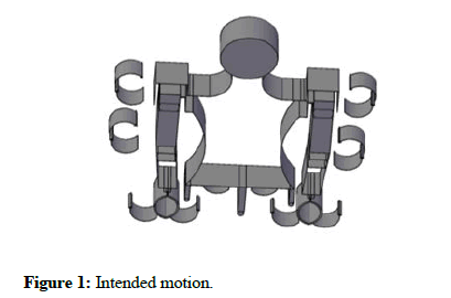
Figure 1: Intended motion.
Selection of appropriate materials: Aluminum was used due to its lightweight since all servo motors used have a specified torque specification. Links were used on the arms since servo motors used on the arm have a maximum stall torque of 11 kg/cm. By using this link, this motor doesn't directly carry the load. It moves the link, and the maximum stall torque isn't exceeded. Rollers are attached to the base to aid the when connected to the DC motor. Rivets pins were used to assemble the structure to prevent the addition of weights. Bolts, nuts and bearings are used at the elbow and shoulder joints to make rotation easy and prevent excess weight, and rollers were also employed at the elbow to aid rotation. Angle bars were riveted into the body to hold the body structure together.
Fabrication and assembly of the machine: After preparing the 3D model of the machine using AutoCAD operations like lathering, step turning, boring/drilling operation, bracing, riveting, welding drilling, boring, step turning, threading, grinding, sheet metal cutting, and mounting of bearings were carried out. The full arm was assembled using fastening like rivet pins, bolt and nuts. Various components are used in the design and construction of 2 DOF arm are listed below
Servo motors: A servo motor is a type of motor that can rotate with a great precision; this motor consists of a control circuit that provides feedback on the current position of the motor shaft; this feedback allows the servo motors to rotate with great precision. It is made up of a motor that runs through a servo mechanism. Most servo motors are classified based on their gear arrangements and operating characteristics. It comes with a gear arrangement that gives very high torque in small and lightweight packages. Due to these features, it was used in our robotic project. A total of six servo motors were used in the project two in the shoulder, elbow and one in the end effector (Figure 2).
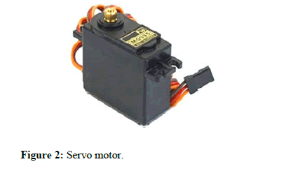
Figure 2: Servo motor.
PIR motion sensor (Components 101, 2017): The PIR sensor stands for Passive Infrared sensor. It is a low-cost sensor that can detect the presence of Human beings or animals. This sensor has three output pins VCC, Output, and Ground, as shown in the pin diagram above. Since the output pin is 3.3V Transistor-Transistor Logic (TTL) logic, it can be used with any platform like arduino, raspberry, etc (Figure 3).
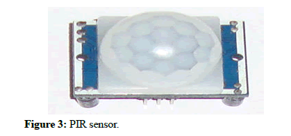
Figure 3: PIR sensor.
The module can be powered from voltage 4.5V to 20V, but, typically 5V is used. Once the module is powered, allow the module to calibrate itself for few minutes, 2 minutes is a well-settled time. Then observe the output on the output pin.
Touch sensor: According to Seeed studio study, the touch sensor is an electronic sensor used to detect human physical touch. It works like a switch when there is pressure, touch, or contact on the surface. It opens up an electrical circuit and allows current to flow.
The touch sensor used was a digital capacitive touch sensor based on a touch-sensing IC TTP223B touch pad detector that offers a onetouch key. The Integrated Circuit (IC) is designed to replace the direct button key with a diverse pad size. The touch sensor is used to detect human physical touch, and it has low power consumption.
Its output is low when not touched and high when a finger touches it. When not touched, it switches to low power mode.
Arduino mega: Arduino mega is a microcontroller based on ATmega 2560. It comes with more memory space and I/O pins compared to other Arduino boards. There are 54 digital pins and 16 analog pins incorporated on the board. Arduino mega is specially designed for projects requiring complex circuitry and more memory space, and that is why It was selected for this project. This board mainly includes everything essential for supporting the microcontroller. So, the power supply of this board can be done by connecting it to a PC using a Universal Serial Bus (USB) cable, battery, or an AC-DC adapter. This board can be protected from unexpected electrical discharge by placing a base plate El-Pro-Cus (Figure 4).
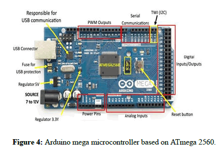
Figure 4: Arduino mega microcontroller based on ATmega 2560.
DC-DC LM 2596 adjustable buck converter: It is also known as a DC-to-DC power converter or buck converter, which is used to step down the voltage from its input supply to the output load Wilsons. The LM2596 buck converter is also known as a step down voltage regulator; in this project, it served the purpose of converting 12V from the adapter to the required voltage needed to make the servo work. It can drive a load under 3A, and the output voltage can be set per our requirement (7V). Other components/sensors are powered by 5 volts from the arduino except for the shoulder, elbow, and 3D-printed hand servos due to its current draw use an external power supply (Figure 5).
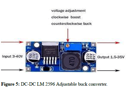
Figure 5: DC-DC LM 2596 Adjustable buck converter.
Results and Discussion
A human being stood in front of the PIR sensor; the shoulder servo extended the shoulder, the elbow servo extended the lower arm. A hand was kept on the 3D printed end effector, and the touch sensor activated the end effector servo, and a grip occurred. After the handshake operation occurred, the arm returned to its initial position (Figure 6).
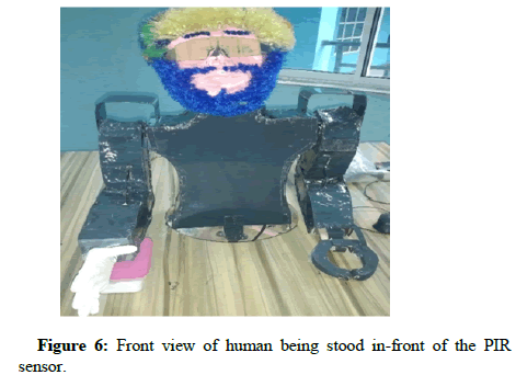
Figure 6: Front view of human being stood in-front of the PIR sensor.
A spot was marked on the workspace, and the object was kept on the area when powered on the end effector, shoulder, and elbow servo extended to the proper position, the dc motor rotated, and the object was dropped in the required spot. After the pick and place operation occurred, the arm returned to its initial position (Figure 7).
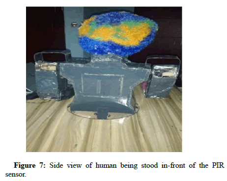
Figure 7: Side view of human being stood in-front of the PIR sensor.
Mechanical implementation
The form was designed from scratch using the bottom-top approach from 8 feet by 4 feet aluminum sheet. The pen was used to mark the shape on the aluminum sheet, and with a grinding/cutting machine, the figures were cut out. The various parts of the form, i.e., shoulder, elbows, frame, were held together using angle bars and rivet pins. A section of 53.6 mm was carved out at the upper region of the frame with the cutting machine so that a servo motor could be attached into the carved section forming the shoulder region. A hole is equivalent to the radius of the mg966r was drilled on the shoulder form and was attached to the body frame using a screw. Rollers were braced into the lower arm to reduce friction during movement and were joined with bolts and nuts. Small pieces of aluminum were machined out on the lower arm region, merged using a link to the elbow servo for easy movement. The end effector was carved out of the aluminum sheet using the cutting machine and attached to the lower arm using rivet pins (Figure 8).
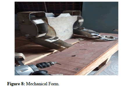
Figure 8: Mechanical Form.
These rollers were later attached to the body for easy rotation on the workspace and to the elbow joints to reduce friction during movement. A compartment was cut out and riveted to the body frame to hold the DC motor in place for easy body rotation (Figure 9).
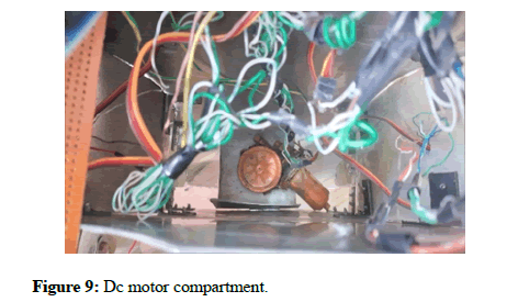
Figure 9: Dc motor compartment.
Electrical implementation: The first step to implementing the circuit was to make a prototype on the breadboard, after the circuit was fully functional; it was implemented permanently on the Vero board. The lead-out wires from the servo motors were connected to the Vero board, and then tapped to the microcontroller (Figure 10).
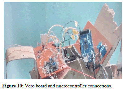
Figure 10: Vero board and microcontroller connections.
A square box was carved out on the body, and wires were fitted in to prevent visibility of connecting wires (Figure 11).
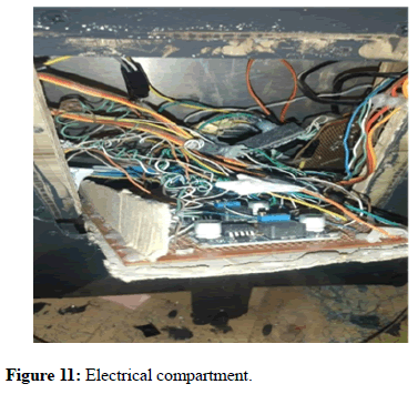
Figure 11: Electrical compartment.
Conclusion
The basic operation starts with simple task as gripping, lifting, moving, placing and releasing in simple robotic arm trajectory. This robotic arm has 2 degrees of freedom and the end of arm has a gripper mechanism on one hand and a 3D printed palm on the other, which is used for the pick, place and perform a hand shake operation. This robotic arm can move in forward, backward, upwards and downward direction.
References
- Ofoegbu Edward. (2020). Introduction to Robotics. Adeleke University, Osun state.
- Chinna RP, Yaswanth KK, Chandu BB, Sasidhar JVS, Harika CM (2020) Android based pick and place robot vehicle for industries. Int Res J Eng Technol 3651-3658.
- Rajgure SD, Chougale AD, Bhatkande AN, Bhamare SA, Chougale SS (2013) A review on design and development of pick and place robotic arm. IOSR J Mech 2018:74.
- Singh P, Kumar A, Vashisth M (2013) Design of a robotic arm with gripper & end effector for spot welding. Univers J Mech Eng 1:92-97.
- Eranki VK, Reddy Gurudu R (2017) Design and Structural Analysis of a Robotic Arm.
- Teli SN, Bhalerao A, Ingole S, Jagadale M, Kharat K (2017) Design and fabrication of pneumatic robotic arm. Int J Sci Eng Res 8:126-132.
- Premkumar S, Varman KS, Balamurugan R (2016) Design and Implementation of multi handling Pick and Place Robotic Arm. J Eng Tren Techno 33:3.
- Yusoff MA, Samin RE, Ibrahim BS (2012) Wireless mobile robotic arm. Procedia Eng 41:1072-1078.
- Laschi C, Mazzolai B, Mattoli V, Cianchetti M, Dario P (2009) Design of a biomimetic robotic octopus arm. Bioinspir Biomim 4:015006.
- Krishna CHM, Chand NVS, Naresh MV, Krishna MV, srigiri CH (2019) Automatic pick and place robotic arm. J Emerg Technol Innov Res 10: 1904A82.
- Harish K, Megha D, Shuklambari M, Amit K, Chaitanya KJ (2017 ) Pick and place robotic arm using Arduino. Int J Sci Res Eng Technol 6:1568-1573.
- Rakhade P (2020) PLC based pneumatic pick and place system. Int Res J Mod Eng Technol Sci 2:823-833.
 Spanish
  Chinese
  Russian
  German
  French
  Japanese
  Portuguese
  Hindi
Hindi 
