 Spanish
  Chinese
  Russian
  German
  French
  Japanese
  Portuguese
  Hindi
Hindi Research Article, J Electr Eng Electron Technol Vol: 6 Issue: 2
A Novel Parallel Modelling-Wavelet Based Mechanical Fault Detection Using Stator Current Signature of Induction Machine under Variable Load Conditions
S. Mahdi Mousavi S*, Aida Mollaeian, Narayan. C. Kar, and Markus Timusk
935 Ramsey Lake Rd, Bharti School on engineering, Laurentian University, Sudbury, ON P3E 2C6, Canada
*Corresponding Author : S. Mahdi Mousavi S
935 Ramsey Lake Rd, Bharti School on engineering, Laurentian University, Sudbury, ON P3E 2C6, Canada
Tel: +1 7056751151
E-mail: smousavisangdehi@laurentian.ca
Received: April 26, 2017 Accepted: June 14, 2017 Published: June 20, 2017
Citation: S Mahdi Mousavi S, Mollaeian A, Narayan C Kar, Timusk M (2017) A Novel Parallel Modelling-Wavelet Based Mechanical Fault Detection Using Stator Current Signature of Induction Machine under Variable Load Conditions. J Electr Eng Electron Technol 6:2. doi: 10.4172/2325-9833.1000143
Abstract
Induction Machine (IM) fault detection techniques such as Fast Fourier Transform (FFT) which is a popular steady-state analysis method is recognized to be highly dependent on the IM loading and speed conditions. Nonetheless, implementing an FFT or even Short Time Fourier Transform (STFT) will result in low resolution frequency characteristics especially under a variable speed and loading conditions. Consequently, fault detection and classification under variable loading and speed conditions is quite inconvenient. Since, mechanical faults are one of the major breakdowns, which occur in IMs, it needs to be addressed to prevent breakage and
fault extension. This paper investigates and detects faults under variable loading and speed conditions by studying the Motor Current Signature Analysis (MCSA) using a novel developed parallel technique based on the discrete wavelet transform (DWT).The proposed model input would be MCSA with the similar drive, loading condition and constraints for both healthy and faulty electric motors and the Discrete Wavelet Transform (DWT) is used as a detection technique. The proposed technique uses the DWT to the IM’s stator current to extract the desired features including Min, Max, Standard deviation, and Energy of the signal as a specific vector for each electric motor. In addition, different mechanical faults including Rotor broken bar(s), eccentricity and bearing have been detected using the proposed technique. Then, the accuracy of proposed parallel model using DWT is verified using experimental set-up of the parallel machines under variable loading and speed conditions for different mechanical faults. Finally the results of the proposed technique for all mechanical faults is tabulated and presented.
Keywords: Fault detection; Induction machine; Wavelet transform; Fourier transform; Parallel system modeling; Features extraction; Standard deviation; Signal energy; Finite elements analysis
Introduction
Even though Induction Machines (IM)s rarely fail, condition monitoring of their health needs to be constantly done. This can be completed through real time data capturing and analysis, which is the most popular solution in order to prevent IM’s failure and outage [1]. Any faults in IMs may interrupt the manufacturing process, and consequently would lead to financial loss in a company [2]. One of the main types of faults in IMs is mechanical faults. Broken rotor(s) fault, bearing, and eccentricity faults are among the most common mechanical faults occurring in IMs Detection of mechanical or electrical faults is achieved by several methods developed so far which is described as [3,4] : 1) electromagnetic field monitoring or in other word axial flux-related detection [5]; 2)temperature measurements [6]; 3) infrared recognition [7]; 4) radio-frequency (RF) emissions monitoring [8]; 5) noise and vibration monitoring [9]; 6) chemical analysis [10]; 7) acoustic noise measurements [11]; and 8) motorcurrent signature analysis (MCSA) which will be considered in this study [12]. There are some advantages and disadvantages for all of these approaches, but due to MCSA’s simplicity and accuracy, this approach has been used widely and also has been utilized in this paper.
To use the MCSA approach, there are several techniques of analysis which are mostly frequency-based approaches and are mostly suitable for fault detection on fixed speed induction machines. In other words, frequency based approaches such as Fourier Transform is suitable if the speed of the drive remains constant for significant periods of time [13]. Nonetheless, variable speed machines are widely used and as a result, there are some key problems that may arise in condition monitoring of variable speed and variable load IM. Since the Fourier transform is not appropriate to analyze a signal that has a transitory characteristics such as drifts, abrupt changes, and frequency trends, when the speed or load are varying considerably, non-stationary approaches, such as Short Time Fourier Transform (STFT) and wavelets transform, should be used [14].
STFT analyzes small sections (windows) of the signal at a time. The STFT provides some information about both time and frequency as a compromise between them. However, a limited precision can be obtained and it is highly related to the size of the window. Moreover, the size of the window should be fixed and it is the main drawback of the STFT [15-17]. Therefore, the wavelet transform was introduced to fix STFT’s drawbacks. The wavelet transform is able to use the windowing technique with a variable-size region of the signal (in this study the signal is the stator current). Wavelet analysis uses long time intervals where more precise low-frequency information is needed and shorter regions where high-frequency information is required. Also local analysis ability is one of the most remarkable advantages of the wavelet transform [18-20]. Due to the Wavelet transforms capability to perform stator current signal analysis during transients, the application of this technique is increasing fast. In addition, the wavelet transform can be used for a localized analysis in the timefrequency or time-scale domain; therefore, it is an effective approach for condition monitoring and fault detection in both variable speed and load condition.
Nonetheless many investigations which have been done in the past to detect broken rotor bar(s) fault, there are still some issues which need to be addressed such as fault detection under different motor loading conditions which is not detectable using FFT or STFT and eccentricity fault of rotor. Moreover, the wavelet based fault detection strategy should meet the required accuracy of reliable fault detection. Therefore, a comprehensive study over the mechanical faults in IM and a detection system, which is capable of addressing all faults under variable speed and loading condition, is needed. To achieve it, this paper aims to propose a novel wavelet based parallel modeling detection technique, which utilizes a vector of features extracted from wavelet coefficients of the stator currents including min, max, standard deviation, and energy of the signal. In other word, the proposed technique is able to detect mechanical faults under transient conditions including variable speed and loading conditions where conventional techniques such as FFT and STFT cannot address them properly. The presences of a fault we be determined based on the parallel system Euclidean distance of the features vector for healthy and faulty machines, this will be explained in detail later. In this paper, the methodology and wavelet overview will be explained in section II. Section III will model the different mechanical faults in IM. The parallel system modeling will be expressed in section IV. Later in section V the experimental setup will be explained and in section VI the results and conclusions will be tabulated and expressed.
Methodology and Discrete Wavelet Transform Overview
In this section, a brief theoretical analysis of voltage equations of induction machine and wavelet transform is presented.
Circuit equations for IM
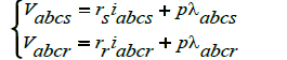
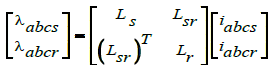
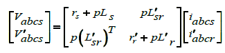
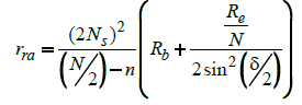
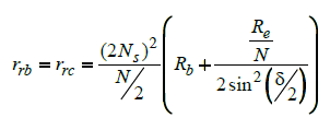
Rotor faults are usually related to the asymmetrical conditions happening due to broken bars, end rings or rotor core damage. As a result, variation in the rotor resistance will cause a discrepancy in the performance characteristics. For a better understanding the phase voltage of IM is presented in (1)-(3); and rotor resistance variation is demonstrated in (4) using geometrical parameters in abc reference frame. If some simplifying assumptions (neglecting leakage fluxes) are adopted for the slip up to the rated value, with the rotor resistances as the main parameter, (4)-(5) is adopted as a per phase rotor resistance where Ns , Rb , Rb and Re are number of turns per phase in the stator, adjacent rotor bar displacement, bar rsesistance and end ring resistance respectively. If n contiguous bars are broken and a-axis is oriented in the direction of the fault, the three equivalent rotor circuits have respectively (N/2−n) and N/2 bars. Therefore, using introduced generic mathematical model, current signature of healthy and faulty IM can be investigated for an increased rotor resistance because of faulty condition.
 (1)
(1)
 (2)
(2)
 (3)
(3)
 (4)
(4)
 (5)
(5)
Wavelet transform overview
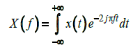
To obtain more information from an unprocessed signal, a mathematical transformation needs to be applied to the signal. In practice, most of the signals are time domain signals, which have time –amplitude representation. In most of the signal processing application, it is not a helpful representation. In fact, the most important information can be extracted from frequency content of the signal, especially in electrical machines fault detection. To get this information, there are several transformations that can be used of which the Fourier Transform (FT) is the most popular. Although FT has been used extensively in different applications, it has several disadvantages. The Fourier transform gives the frequency information of the all frequency spectra in the signal but it cannot express any information about the time of all frequencies in the frequency spectra. Therefore, the Wavelet transform is the popper solution for signal analysis in fault detection. To express the wavelet transform well, an explanation of the Short Time Fourier Transform (STFT) is needed. The Fourier transform decomposes the signal into a function of his frequencies, which expressed in (6):
 (6)
(6)
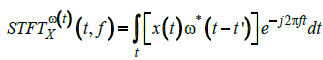
Where t is time, f is the frequency, and x is the time-domain signal. The difference of STFT with Fourier transform is that in Short Time Fourier transform, the signal is distributed into small enough sections that it can be considered as a stationary signal. In STFT approach, a window function will be chosen and shifted along the time axis. The window length should be similar to the time segments of the signal. The STFT has been defined in (7):
 (7)
(7)
Where ω(t) is the window function, and it can be seen that the STFT is the Fourier transform of the x(t) but applying the window function. When applying the STFT to a fast time varying signal, a narrower window will result in a stationary signal, which is the main assumption here. However, this will cause a poorer frequency resolution. Therefore, it can be concluded that the wider window has better frequency resolution but poor time quality and also may disturb the stationary assumption of the signal which is similar to Gabor limit in time-frequency analysis to uncertainty.
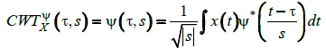
Therefore, the Wavelet transform including Continuous Wavelet Transform (CWT) and Discrete Wavelet Transform (DWT) should have been used. The CWT has been established to overcome the deficiencies of STFT with the same approach. In CWT the signal is multiplying with the wavelet which is similar to the window function on the STFT, but the transform is formed separately for each time segment of time. The CWT is expressed in (8):
 (8)
(8)
In (8) the CWT signal is a function of (τ and s), which are the translation and scale factors in order. ψ(t) is the mother wavelet which transform the signal and the translation word means exactly the same in STFT which is the location of the window along the signal and it is related to time information of the wavelet transform. The factor of scale is also corresponds to the non-detailed and detailed view of the signal for high scales and low scales respectively. It is exactly similar to the frequency analysis which high frequency (low scales) corresponds to the detailed information and vice-versa.
In CWT the mother wavelet should be selected first, then CWT starts with s=1 and it shifts along the time axis by τ.
In all of these steps (8) is calculated to obtain the CWT value for s=1 and t=τ and other steps till the end of the signal time in timefrequency area. This will be done for all imposed value of s. The idea of the discrete wavelet transform (DWT) is similar to the CWT, but it is extremely easier and faster to be employed.
In digital signal processing, using of digital filters results in time-scale representation of the signal. Filters with different cutoff frequencies are used for signal processing with different scales. To analyse the high frequencies of the signal high pass filters will be used and for lower frequencies, low pass filters. In other word, DWT analyse the signal at different frequency bands and resolution by decomposing the signal into a set of approximation and detail information. In DWT, two sets of scaling and wavelet functions are used in accordance with low pass and high pass filters respectively. Figure 1 depicts the signal decomposition using of the DWT.

Figure 1: DWT technique with db 4 mother wavelet and 5 levels.
The main signal of x in first step, passes through a high pass filter (HPF) and a low pass filter (LPF). After the filtering, half of the data will be disregarding based on the Nyquist’s law. The filtering eliminates a part of the frequency information but the scaled will be kept unchanged. This one level of decomposition can be repeated for further decomposition. It should be noted that in each level of decomposition, the filtering and sub sampling will eliminate half of the samples and half of the frequency spanned. It can be continued until the prominent frequency of the signal appears with high amplitude in the area of DWT signal with those frequencies. The most important advantage of this approach compared to Fourier transform is that the time localization of these frequencies will not be lost. In other word, DWT offers a proper time resolution at high frequencies, and good frequency resolution at low frequencies [21-27].
Methodology
Since in many industrial applications parallel machinery have been used widely, the parallel modeling fault detection could be very useful. As mentioned previously, in this study, parallel system modeling has been developed to detect the mechanical faults in induction machines. In this novel parallel system approach, both machines should be in the same loading and drive condition. Parallel system modeling has been depicted in Figure 2.
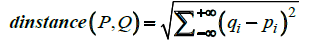
According to Figure 2, there are two identical motors M1and M2 which are running the same load fIM(R). As depicted in Figure 2 variable loading and speed conditions have been considered. Motor current signature will be captured for further analysis. Therefore, MCSA (Ia1, Ib1, Ic1) and DWT (db4 mother wavelet) techniques will be used for both IMI and IMII. Db4 with 5 levels of decomposition hass been used and the level 5 (d5) detail of both IMs have been captured to extract the features presented in Figure 2. Maximum, standard deviation, and energy of the signal [f1 f2 f3] are the correspondence features. Euclidean distance is the best distance tool to calculate the distance of 2 feature vectors of both IMs  . The distance the will compared with the distance of 2 healthy paralleled machine to detect any possible mechanical faults.

Figure 2: Parallel system modeling fault detection approach.
It should be noted that there are several features that can be extracted from the wavelet details including Mean Absolute Value (MAV), Simple Square Integral (SSI), Root Mean Square (RMS), but after applying different features for this application, the previously mentioned features showed the best track of fault detection. One of the advantages of these features, which results better than the rest of the features, is that they are based on time domain and keep the time domain specifications too.
 (9)
(9)
(9) expresses the signal energy calculation over the time
 (10)
(10)
Signal maximum can be extracted using (10)
 (11)
(11)
Standard deviation calculation is expressed in (11)
 (12)
(12)
(12) shows the Euclidean distance to get the residual of the feature vector.
In this study the motor one is a healthy machine (H) in all tests, but the motor two will be healthy in first test and will be replaced later with different faulty machines (F1, .. Fn) for other tests. All tests’ results for healthy-faulty machines residual (R) will be compared with the healthy-healthy test residual to detect the fault. This approach is one of the most effective methods for fault detection due to 2 merits such as: 1. it can be applied on-line to parallel machinery and 2.
The residual, which is derived from the identical motors features' vector under same condition (both healthy and faulty). According to the proposed technique, which is based on three different prementioned features and the distance function i.e. Euclidean distance for the parallel motors application, the more sample i.e. shorter sampling time, results in a more precise and even faster detection.
In this approach, different wavelet filters can be used but based on this study's best of experience, db4 mother wavelet with 5 levels of filtering is the best solution to extract the details of the motor current signature, and the features of signal energy, maximum value and standard deviation results in a very proper detection which will be explained more in result section.
Mechanical Fault Modeling
In order to model IM, a 2-D time-stepping finite element (2-D TS-FE) model has been adopted to analyze magnetic flux density and stator phase current of the model at various time steps and speeds of a solution over a specified period of time. The fixed mesh simulation is executed with healthy motor, as well as one, two, and three adjacent broken bars, and at a slip of 0.66, 0.33 and 0.02. The variables are updated based on a time dependent motion equation component in the z-direction based on solution of Maxwell’s equation.
This resulted in 16128 mesh elements for the band, shaft, outerregion, stator, coils, rotor and bars with minimum and maximum edge length of 1e-006 and 0.00742462. By running the fixed mesh simulation incorporating current signatures is distinguished for each case study. Table 1, presents the geometrical and electrical parameters of three-phase squirrel cage induction machine used in 2-D TS-FE analysis. IM with, one, two and three broken bars are treated as a nonmodel objects to perform the corresponding faults.
| Rated Parameters | Geometrical parameters | ||
|---|---|---|---|
| Output power | 7.5 hp | Dso/Dsi | 220.137/134 |
| Phase voltage | 200 V | Dro/Dri | 133.4/42 |
| Phase current | 20.9 A | Stator slot number | 48 |
| Number of poles | 4 | Rotor slot number | 42 |
| Frequency | 60 Hz | Stack length | 136.02 mm |
| Synchronous speed | 1,800 rpm | Conductors/slot | 120 |
Table 1: Rated and geometrical parameters of initial IM for 2-d FE modeling.
To analyse resultant faults, the proposed parallel system, which is explained in Figure 2 is developed and applied to three-phase IM in exactly same condition for all healthy and faulty motors.
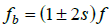
Magnetic flux density distribution under variable speed/ loading condition is symmetrical for healthy IM, while higher degree of magnetic saturation is detected because of the absence of local demagnetization slip frequency-induced current around the broken bars. Therefore, the mechanical performance characteristics of the induction motor are affected by circuit parameter variation specifically the rise in rotor resistance. The stator current depends on the equivalent value of the rotor resistance, and the level of the component (1±2s)fs due to the additional oscillations developed in the rotor speed which is producing an alternating component in torque with frequency of 2sfs.
Samples of magnetic flux map for IM variable speed conditions for the cases of healthy, one, two and three broken bars are presented in Figures 3-7. Figures 4a and 4b depicts the FEA model of the healthy IM under the variable load and speed condition. It will be the same conditions for faulty machines plus same motor drive and control strategy. Figure 5 represents the 1 broken rotor bar fault under same loading and speed condition. It has been depicted the difference of field plot in the same cut of the induction machine. Figure 6 and Figure 7 depicts the same condition and same motor with 2 and 3 broken rotor bars fault respectively. Here it can be seen clearly the differences between the healthy and faulty motors field plots are more sensible compare to 1 broken rotor fault.

Figure 3: Induction machine sub-domains mesh

Figure 4: FEA model of healthy IM under variable speed and loading condition, magnetic vector potential.

Figure 5: FEA model of one broken rotor bar IM under variable speed and loading condition, magnetic vector potential.

Figure 6: FEA model of two broken rotor bars IM under variable speed and loading condition, magnetic vector potential.

Figure 7: Half FEA model of IM rotor eccentricity fault under variable speed and loading condition, magnetic vector potential.
Figure 8 depicts the speed of the both parallel motors in all tests. Based on the FEA simulation results, it is clear that when a mechanical fault happens, due to the severity of the fault, it has effects on the flux and fields of the electric machines. Therefore, this will result in changing the features of the motor current signature. However, to detect this, the proposed parallel system and wavelet based signal analysis as a novel detection approach should be applied. The motor current signature should be captured and applied to the wavelet transform with the proper mother wavelet and levels of filtering. In this study according to the literature review, the db4 mother wavelet and level of 5 is the most proper value for this application. Selecting any mother wavelet can have an effect on the extracting procedure of the features of the details waves (generated harmonics), therefore an effort has been done to explore the different types of the filters [20]. After all examinations, db4 has been found superior over other standard Daubichies (db2 and db6). It is due to its ability to avoid low level overlapping with nearby bands. Therefore, in variable load and speed conditions db4 presents the best performance compare to other mother wavelets The 5th level detail of the current signature has the proper time-frequency information for fault detection in mechanical faults detection of IM if the appropriate feature from the details has been extracted. Figure 9 depicts the 5th detail of FEA simulated current signature of the proposed parallel system with defined faults. Figure 10 shows the same information for the developed parallel system in experimental analysis. Using Maxwell software for fault simulation result in required current signatures for fault detection. Then Wavemenu toolbox in Matlab software has been used to extract the details of the currents. The window length of the wavelet in (7) which should be as equal as the segment of the signal where its stationary is valid, will be detected by the program itself in all wavelet processing

Figure 8: Variable load (N.m) condition of the developed parallel machine.

Figure 9: 5th detail of phase a current signature of simulated tests a: healthy, b: one broken bar faulty, c: 2 broken bars faulty, d: rotor eccentricity faulty machine.

Figure 10: 5th detail of phase a current signature of experimental tests of a: healthy, b: 4 broken bars faulty and c: Bearing rotor faulty machine.
In this research based on studying different approaches, predefined features (4)- (6) aimed to be extracted and applied for fault detection. Therefore the vector of features extracted from wavelet analysis would be [standard deviation, Maximum, Signal energy].
In this step, a perfect distance index is needed to represent the distance of the motor with a healthy motor features vector. To achieve that, Euclidean distance as a powerful and the most popular tool to calculate the distance will be used applying (7).
To verify the proposed parallel system modeling for fault detection in induction machine, the experimental set up has been developed as it can be seen in Figure 9. According to this set up, two identical induction motors have been run in parallel. A single controller drives both motors and it results in exactly the same motor control strategy. Both motors run the same hydraulic load, which is programmable through the online control system in the setup. In the developed experimental test bench, the motor current signature, speed, torque and vibration can be captured online through the data logging system and sensors using the FPGA card and probes connected to the system. The induction motors speed and hydraulic load can be changed online or programmed in advance. All the power components and control systems have been depicted in Figure 11 and Figure 12.

Figure 11: Experimental setup of the parallel system fault detection of induction machines.

Figure 12: control system and online data logging system of the developed experimental setup.
Experimental Set-up and Verification
In this research, Lab view has been used as the master programmer to apply the defined variable load and speed tests on all tests. Three different tests have been done with similar speed and load profile. The first test was done with two paralleled healthy induction machines to capture the motor current signatures and their feature vector through discrete wavelet analysis and finally their distance index, which is expected to be very low since both motors, are identical and healthy. There should be a small difference due to aging factor. Since this test has been done under variable speed and load condition, for all situations, the whole process of Figure 2 will be done to achieve the distance value and detection.
The second test has been done with a healthy motor in parallel with 4 broken rotor bars motor. The rotor was drilled at both ends, such that the hole cut through each end of the rotor bar. This breaks the electrical continuity across the rotor bar. This method of faulting the rotor is done to replicate a crack through the rotor bar, which will have the same effect of rendering the bar unable to conduct a current. The same load and speed profile with test one was applied. The third test was a healthy motor in parallel with an eccentricity rotor fault. Similar to the previous two tests, this one kept the same loading and speed profile, which its results could be comparable and meaningful for the fault detection. Figure 13 depicts the two mechanical faults including broken rotor bar and eccentricity rotor faults. Both the simulation and experimental tests results are based on the proposed parallel approach and wavelet based signal analysis and have been tabulated in next section.

Figure 13: Broken rotor bar fault (left) and unbalance rotor fault (right).
Results and Conclusion
Using the captured data from both FEA simulation and experimental test-bench of proposed parallel system detection and applying the discrete wavelet transform to get the detail results in the prepared information for signal processing and fault detection. The result has been processed using (7) - (9) to get the feature vector for both motors in each test. Finally the distance index of (10) has been used to calculate the Euclidean norm of both motors features vector to detect if any fault has occurred or not.
It should be noted that since the presence of noise in industrial applications are inevitable, therefore in all simulations, the white noise with Signal to Noise ratio (SNR) of 10 has been applied. To achieve it, the Matlab white noise function “awgn(x,snr)” has been used in all fault models for all mechanical faults and all detection process has been applied considering the noise.
Table 2 depicts the feature vectors and final Euclidean distance for 5 different tests including test1: healthy-healthy machines 2: healthy-one broken bar faulty machine 3: healthy-2 broken rotor bars faulty machines 4: healthy-3 broken rotor bars faulty machine and 5: healthy-rotor eccentricity faulty machines.
| Simulated Mechanical Faults of Novel Parallel System Fault Detection | |||
|---|---|---|---|
| Parallel System of 1 Broken Rotor Faulty Motor & Healthy Motors | |||
| Standard Deviation | Maximum | Energy Signal | Euclidean Distance |
| 1B: 0.0093 H: 0.0063 |
1B: 0.0409 H: 0.0410 |
1B: 0.1072 H: 0.5071 |
0.1064 |
| Parallel System of 2 Broken Rotors Faulty Motor & Healthy Motors | |||
| Standard Deviation | Maximum | Energy Signal | Euclidean Distance |
| 2B: 0.0179 H: 0.0063 |
2B: 0.0646 H: 0.0410 |
2B: 0.4009 H: 0.5071 |
0.3502 |
| Parallel System of 3 Broken Rotors-Eccentricity Faulty Motor & Healthy Motors | |||
| Standard Deviation | Maximum | Energy Signal | Euclidean Distance |
| 3B-E: 0.027 H2: 0.0063 |
3B-E: 0.0836 H2: 0.0410 |
3B-E1: 0.9245 H2: 0.5071 |
0.8738 |
| Parallel System of 1 Broken Rotor Faulty Motor & Healthy Motors | |||
| Standard Deviation | Maximum | Energy Signal | Euclidean Distance |
| H1: 0.0063 H2: 0.0078 |
H1: 0.0410 H2: 0.0597 |
H1: 0.0507 H2: 0.0776 |
0.0269 |
Table 2: Proposed parallel system fault detection results for fea simulated model.
Table 3 shows the feature vectors and final Euclidean distance for 3 different experimental tests including test1: healthy-healthy machines 2: healthy-four broken bars faulty machine 3: healthy-bearing rotor faulty machines. According to both Table 1 and Table 2, it is clearly detectable that the proposed parallel system modeling fault detection using wavelet transform can detect all mechanical faults precisely and fast. It can be seen that the more severe faults results in a higher Euclidean distance and therefore absolutely clearer fault. Both simulated faults and experimental tests showed the proposed fault detection is applicable and trustworthy in electric motors fault detection and also based on the detection, it can be said that besides the high precisions, all faults can be detected in a very short time less than seconds.
| Experimental Mechanical Faults of Novel Parallel System Fault Detection | |||
|---|---|---|---|
| Parallel System of 4 Broken Rotors Faulty Motor & Healthy Motors | |||
| Standard Deviation | Maximum | Energy Signal | Euclidean Distance |
| 4B: 0.0039 H: 0.0040 |
4B: 0.0361 H: 0.0419 |
4B: 0.2462 H: 0.2565 |
0.0202 |
| Parallel System of Unbalanced Rotor & Healthy Motors | |||
| Standard Deviation | Maximum | Energy Signal | Euclidean Distance |
| UR: 0.0039 H: 0.0038 |
UR: 0.0334 H: 0.0326 |
UR: 0.2439 H: 0.2379 |
0.0118 |
| Parallel System of 2 Healthy Motors | |||
| Standard Deviation | Maximum | Energy Signal | Euclidean Distance |
| H1: 0.0045 H2: 0.0044 |
H1: 0.0251 H2: 0.0244 |
H1: 0.3358 H2: 0.3156 |
0.006 |
Table 3: Proposed parallel system fault detection results for experimental setup.
On the other hand, Figures 14 and Figure 15 depict that FFT analysis cannot detect mechanical faults such as broken rotor fault under the variable load and speed condition. According to FFT spectrum analysis of machine line current (MCSA) to detect broken bar faults, the sideband components around the fundamental for detecting broken bar faults is:
 (13)
(13)

Figure 14: FFT spectra of healthy machine with variable speed and load condition.

Figure 15: FFT spectra of 3 broken bar faulty machine with variable speed and load condition.
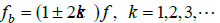
while the lower sideband is specifically due to a broken bar, the upper sideband is due to consequent speed oscillation. In fact, the broken bars actually give rise to a sequence of such sidebands given by (14)
 (14)
(14)
It can be seen in Figure 14 and Figure 15 that under variable speed and load condition, the FFT analysis cannot detect the broken bars fault and 14 works under non-stationary situations.
In another point of view, it has been verified that the wavelet transform based detection in parallel systems under variable load and speed conditions works very well and can keep all the transients in time domain beside the harmonics information, which is necessary in non-stationary situations.
Due to the advantages of this approach (precise, fast loading), it can be used as on-line fault detection or health monitoring of electric motors. Moreover, based on the different faults results it can be seen that the proposed method is a truthful detection, which is applicable for variable speed and loading condition and easily can be modified for fault diagnosis as well. Finally, this method is so fast and easy to be applied in real systems. Using of any data logging system including all sensors, I/O cards and controller, which needs to be equipped with Labview and Matlab software to analyze the current signature, the proposed algorithm is able to detect all possible mechanical faults, which have been expressed in this study.
References
- Silva AM, Richard J, Demerdash AO (2008) Induction Machine Broken Bar and Stator Short Fault Diagnostic Based on Three Phase Stator Current Envelope. IEEE Transaction on Industrial Electronics 55: 1310-1318.
- Zhang Z, Ren Z, Huang W (2003) A Novel Detection Method of Motor Broken Rotor Bars Based on Wavelet Ridge. IEEE Transactions on Energy Conversion 18: 417-423.
- Kia SH, Henao H, GA Capolino (2007) A High-Resolution Frequency Estimation Method for Three-Phase Induction Machine Fault Detection. IEEE Transactions on Industrial Electronics 5: 2305-2314.
- Peng ZK, Chu FL (2004) Application of the Wavelet Transform in Machine Condition Monitoring and Fault Diagnostics: A Review with Bibliography. Journal of Mechanical System and Signal Processing 18: 199-221.
- Filippetti F, Franceschini G, Tassoni C, Vas P (2000) Recent Developments of Induction Motor Drives Fault Diagnosis Using AI Techniques. IEEE Transactions on Industrial Electronics 47: 994-1004.
- Benbouzid MEH, Kliman GB (2003) What Stator Current Processing-Based Technique to use for Induction Motor Rotor Faults Diagnosis? IEEE Transactions on Energy Conversion 18: 238-244.
- Chow TWS, Hai S (2004) Induction Machine Fault Diagnostic Analysis with Wavelet Technique. IEEE Transactions on Industrial Electronics 51: 558-565.
- Lined A, Supangat RK, Grieger J, Ertugrul N, Soong WL (2004) A Baseline Study for On-Line Condition Monitoring of Induction Machines. Australasian Universities Power Engineering Conference (AUPEC), Australia.
- Ayhan B, Chow MY, Song MH (2006) Multiple Discriminant Analysis and Neural-Network-Based Monolith and Partition Fault-Detection Schemes for Broken Rotor Bar in Induction Motors. IEEE Transaction on Industrial Electronics 53: 1298-1308.
- Nandi S, Toliyat HA, Li X (2005) Condition Monitoring and Fault Diagnosis of Electrical Motors-A Review. IEEE Transactions on Energy Conversion 20: 719-729.
- Bellini A, Filippetti F, Franceschini G, Tassoni C, Klimai GB (2001) Quantitative Evaluation of Induction Motor Broken Bars by means of Electrical Signature Analysis. IEEE Transactions on Industry Applications 37: 1248-1255.
- Jose P, Bindu VR (2014) Wavelet-Based Transmission Line Fault Analysis. International Journal of Engineering and Innovative Technology 3.
- Mirafzal B, Demerdash AO (2006) An Innovative Methods of Induction Motor Inter-turn and Broken Bar Fault Diagnostics. IEEE Transactions on Industry Application 42: 405-410.
- Kliman GB, Prenerlani WJ, Yazici B, Koegl RIA, Mazereeuw J (1997) Sensorless, Online Motor Diagnostics. IEEE Computer Applications in Power 10: 39-43.
- Xu B, Sun L, Xu L, Xu G (2013) Improvement of the Hilbert Method via ESPRIT for Detecting Rotor Fault in Induction Motors at Low Slip. IEEE Trans. Energy Convers 28: 225-233.
- Henao H (2014) Trends in Fault Diagnosis for Electrical Machines. IEEE Ind Electron Mag 8: 31-42.
- Mohanty AR, Kar C (2006) Fault Detection in a Multistage Gearbox by Demodulation of Motor Current Waveform. IEEE Trans on Ind Electron 53: 1285-1297.
- Riera-Guasp M, Antonino-Daviu JA, Capolino GA (2015) Advances in Electrical Machine, Power Electronic, and Drive Condition Monitoring and Fault Detection: State of the Art. IEEE Transactions on Industrial Electronics 62: 1746-1759.
- Rangel MJ, RomeroTRJ, Contreras MLM, Garcia PA (2008) FPGA Implementation of a Novel Algorithm for On-Line Bar Breakage Detection on Induction Motor. IMTC 2008, IEEE 720-725.
- Phinyomark A, Nuidod A, Phukpattaranont P, Limsakul C (2012) Feature Extraction and Reduction of Wavelet Transform Coefficients. Journal of Electronics and Electrical Engineering Signal Technology 122: 27-32.
- Immovilli F, Bianchini C, Cocconcelli M, Bellini A, Rubini R (2013) Bearing Fault Model for Induction Motor with Externally Induced Vibration. IEEE Trans Ind Electron 60: 3408-3418.
- Gritli Y (2013) Advanced Diagnosis of Electrical Faults in Wound Rotor Induction Machines. IEEE Trans Ind Electron 60: 4012-4024.
- Joksimovic GM, Riger J, Wolbank TM, Peric N, Vašak M (2013) Stator-Current Spectrum Signature of Healthy Cage Rotor Induction Machines. IEEE Trans Ind Electron 60: 4025-4033.
- Vedreño-Santos F, Riera-Guasp M, Henao H, Pineda-Sánchez M, Puche-Panadero R (2014) Diagnosis of Rotor and Stator Asymmetries in Wound-Rotor Induction Machines under Nonstationary Operation through the Instantaneous Frequency. IEEE Trans Ind Electron 61: 4947-4959.
- Mohammadpour A, Sadeghi S, Parsa L (2014) A Generalized Faulttolerant Control Strategy for Five-Phase PM Motor Drives Considering Star, Pentagon, And Pentacle Connections of Stator Windings. IEEE Trans Ind Electron 61 63-75.
- Climente-Alarcon V, Antonino-Daviu JA, Riera-Guasp M, Vlcek M (2014) Induction Motor Diagnosis by Advanced Notch FIR Filters and the Wigner-Ville Distribution. IEEE Trans Ind Electron 61: 4217-4227.

