Spanish
  Chinese
  Russian
  German
  French
  Japanese
  Portuguese
  Hindi
Hindi Research Article, Res Rep Metals Vol: 1 Issue: 3
A Polymer Route to the Design of Thermally Stable Metal Matrix Composites: Materials Selection and In-situ Processing
Chelliah NM1,2, Sudharsan1, Lisa Kraemer3, Harpreet Singh2, Surappa MK4 and Rishi Raj1,2*
1Department of Mechanical Engineering, University of Colorado Boulder, Boulder, Colorado, USA
2Department of Mechanical Engineering, Indian Institute of Technology, Ropar, India
3Erich Schmid Institute of Material Science, Austrian Academy of Sciences, A-8700 Leoben, Austria
4Department of Materials Engineering, Indian Institute of Science, Bangalore, India
*Corresponding Author : Rishi Raj
Department of Mechanical Engineering, University of Colorado Boulder, Boulder, Colorado, USA
Tel: 303-492-1029
E-mail: Rishi.Raj@colorado.edu
Received: April 13, 2017 Accepted: August 27, 2017 Published: September 01, 2017
Citation: Chelliah NM, Sudharsan, Kraemer L, Singh H, Surappa MK, et al. (2017) A Polymer Route to the Design of Thermally Stable Metal Matrix Composites: Materials Selection and In-situ Processing. Res Rep Metals 1:3.
Abstract
The microstructural design of metal matrix composites for elevated temperature structural applications has two needs: (i) the ceramic phase must be dispersed at the nanoscale, and lie within the grain matrix, and (ii) the dispersed phase should not coarsen at high temperatures. Many ceramics, both oxides and non-oxides are currently produced from polymer precursors. The potential for incorporating these ceramics into a metal via in-situ conversion of polymers can address both the requirements. Most often the polymers are environmentally benign. These polymers are self-contained, that is all constituents of the ceramic phase are present within the organic molecules. The diversity of materials selection and processing approaches can spur further innovation. Among them, the silicon-based polymers convert into the silicon oxy-carbonitride (Si-C-N-O) phase in the temperature range of 800 – 1000 oC. The polymer can be infused into molten metal by stir-casting method, as in magnesium, or, in the solid state, by mechanical milling of the polymer and metal powders, as in copper. In this article, the recent development on the processing approaches, and mechanical properties of the polymer derived metal matrix composites are reviewed. Some of the newer results of magnesium matrix composites are also discussed. The primary advantages of silicon-based polymer and its role on enhancing the creep-rupture performance of magnesium matrix composites at ~0.8TM (450 oC) are summarized. The current processing challenges and the potential for scale-up and manufacturability of composites will be addressed.
Keywords: In-situ composites; Stir-casting; Ball-milling; Friction stir-processing; Microstructures; Mechanical properties; Creep-rupture
Introduction
Metal matrix composites (MMCs) refer to family of hybrid materials in which hard ceramic particles are dispersed in the ductile metallic matrix. MMCs are capable of providing improved mechanical strength, wear resistance, high temperature creep resistance or dimensional stability when subjected to dynamic and thermal disturbances [1,2]. Thermo-mechanical properties can easily be tailored in MMCs by varying the volume fraction, and size of ceramic particles. MMCs are most commonly fabricated by variants of conventional processing techniques; (i) physical mixing of ceramic powders with the liquid metal by stir-casting method [3], (ii) forced infiltration of the liquid metal into porous preforms of a ceramic phase [4], (iii) mechanical mixing of powders of a metal and the ceramic particles in the solid state followed by hot-consolidation [5], and (iv) severe plastic deformation in the solid state by deformation processes; thoriated nickel is an example of this method [6]. Solidification processing is the most economical, viable and versatile process to fabricate MMCs for large scale manufacturing sectors [7]. However, solidification processing is not well-suited for achieving uniform dispersion of fine-sized ceramic particles owing to the formation of hard agglomerates by the Van der Waals force of attraction [8]. In-situ composite fabrication techniques seem to be gaining attraction since it overcomes several issues (non-uniformity of particle distribution, poor wettability and weak interfaces) associated with composites produced by conventional processing techniques [9-10]. In general, in-situ MMCs consist of ultrafine-sized and thermodynamically stable ceramic particles, clean and unoxidized ceramic-metal interfaces with high interfacial strength, due to improved wettability. Investigators at the University of Colorado and the Indian Institute of Science have been collaborating to explore the possibility of enhancing the high temperature creep performance in polymer-derived metal matrix composites (P-MMCs) by utilizing the in-situ pyrolysis approach [11-18]. A unique feature of the P-MMC process is that all constituents of the ceramic phase are built into the polymer molecules. Therefore, no chemical reaction is required between the polymer precursor and the host metal to produce ceramic particles. Furthermore, the in-situ pyrolysis is a highly reactive process, accompanied by the evolution of hydrogen, which fragments and disperses the micron-sized ceramic phase into Nano scale or sub-micron constituents [11,12].
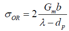
The yield strength and creep properties of MMCs are determined by being able to impede the glide of dislocations at room temperature and climb of dislocations at high temperatures, which depends greatly on the particle size [19]. The mechanisms of glide and climb of dislocations also change with the volume fraction of the second phase. At high volume fractions where the metal channels between the particles may be narrower than the average spacing between the dislocations; their movement is geometrically constrained [20]. The γ- γ' single crystal super alloys are a sterling example of how high volume fractions of the γ' phase can be employed to achieve creep resistance at very high temperatures [20]. More commonly, Nano scale particles of the second phase are dispersed in dilute volume fractions to enhance the yield strength and creep resistance at elevated temperatures. In material design, the upper bound for the yield stress  is given by the Orowan equation [21] as follows:
 (1)
(1)
Where, Gm is the shear modulus, b is the Burgers vector, dp is the size of the particles and λ is the spacing between the particles. The factor of 2 converts shear into tensile stress.
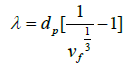
Assuming the particles to be in the shape of cubes that are distributed in a cubic lattice, gives the following relationship:
 (2)
(2)
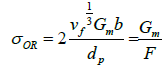
For dilute dispersions, λ >> dp and the Equation 1.1 can be simplified to:
 (3)
(3)
 (4)
(4)
Note that the Orowan stress depends primarily on particle size of dp , and much less so on volume fraction of vf For instance, if the Orowan strength equal to 1% of the modulus is desired, that is, F =100, and if the volume fraction is equal to vf=0.01 then by assuming b =0.15 nm Eq. (3) gives that dp =6.5 nm. Increasing the volume fraction to 10%, makes a minor change in dp =15 nm.
Therefore, Eq (3) clearly demonstrates that Nano scale particles are needed for meaningful increase in the Orowan strength or yield stress. Nano-scale particles of PDCs dispersed into metals can be expected to impede dislocation motion and resist coarsening at high temperatures, thereby holding the promise of a new genre of polymerderived P-MMCs.
At high temperatures the flow stress depends on temperature and strain rate [22,23], but will always be lower than the Orowan stress. Mechanistically, creep resistance is controlled by the rate at which dislocations can climb over the particles; the regimes of temperature and strain rate where one mechanism dominates over the others have been represented in deformation mechanism maps [23]. The maps are for primarily pure metals; still they provide a framework for the design of engineering materials. In high temperature structural applications the dislocation creep regime matters. The microstructural criteria for the design of MMCs for elevated temperature applications includes (i) the particles of the second phase need to be nanoscale, (ii) the particles should not coarsen at high temperature, which means that the second phase must be essentially insoluble in the metal matrix, and (iii) the particle-matrix interface should be effective in trapping dislocations, which implies the interface should have low energy, a low contact angle, and strong atomistic bonding. Myriad other in-situ reactions, where the particles are a product of a foreign constituent and the metal host have been discussed in the literature, but these reaction pathways are complex and difficult to understand [9-10], and usually not feasible for large-scale manufacturing process. The only example of a commercial alloy produced in this way is where copper is reinforced with alumina by internal oxidation of dilute aluminium-copper alloys [24]. In this review article, guidelines to material selection of polymer precursors, and recent development on liquid-, solid-state and dual processing techniques, and the obtained mechanical properties are discussed. The vastly improved stress-rupture properties of magnesium matrix composites at ~0.8TM (450°C) are also summarized [18].
Selection of Polymer Precursors
Polymer derived ceramics (PDCs), so called because they are made from organic precursors which, when heated, typically, from 400°C to 1000°C, decompose to yield ceramics. They fall into two classes, those that produce oxide phases such as ZrO2, TiO2, SiO2 etc. [25], and those that produce silicon based ceramics. The latter include SiC [26] and also amorphous ceramics that are constituted from Si-C-N-O [25]. List of commercially available polymer precursors are summarized in Table 1[11]. It is important to keep in mind that the properties of various precursors summarized in Table 1 are not sacrosanct. For example, the molecular weight of the precursors can be varied to control their volatility, and vinyl side groups can be added to enhance their ability to cross-link. If high vapor pressure is preferable, to inject the precursor with a carrier gas directly into the liquid melt, then precursors of low molecular weight, but with the same essential chemistry, can be created. These innovations will be engendered by new partnerships between the chemist and the metallurgist [11]. The most common organics for amorphous ceramics are silicones (chemical name is polysiloxanes) which yield amorphous SiCO ceramics [27]. The SiC ceramics are made from polycarbosilane precursor [28]. The silicones have the added advantage of being a much lower cost material than the polysilazanes. Most often these precursors are liquids; if they are solids they can be dissolved in common organic solvents. The organics that produce the oxides are called alkoxides because the alkyl groups – the hydrocarbons – are attached to oxygen atoms in the molecule via the –O–CnH2n+1 bond. The oxygen atoms bridge the metal to the carbon. These are low molecular weight molecules. For example in zirconiumethoxide, the zirconium atom bonds with four –OC2H5 groups. The molecule decomposes into the oxide when heated to about 400°C as follows [29];
| Organic precursors | Ceramic phases | Advantages | Disadvantages |
|---|---|---|---|
| Polysilazanes | Si-C-N-O (amorphous) |
•Commercially available •Mostly air tolerant •Can be thermally cross–linked •High molecular weight. •Environmentally benign and mostly not inflammable • Pyrolyze at 800-1000°C |
•Silicon can form silicides |
| Siloxanes | Si-C-O (amorphous) |
||
| Carbosilanes | Si-C (crystalline) |
||
| Alkoxides | Metal oxides, e.g. silica, zirconia, titania, hafnia, alumina, etc. | •Commercially available •Moderately air tolerant. • Pyrolyze at 400°C |
•Cannot be cross–linked •High vapor pressure |
Table 1: Types of organic precursors that yield ceramics when heated to 400°C to 1000°C Sudarshan et al. [11].
 (5)
(5)
These compounds have a high vapor pressure, and therefore must be injected into the liquid melt in vapour form using a carrier gas (like the Bessemer process for bubbling oxygen). While there is potential for making polymer-derived metal matrix composites (P-MMCs) from alkoxides, the method remains unproven. Classical materials such as thoriated-nickel which was made by mechanical alloying [6], and a variety of oxide dispersion strengthened metals should be possible by the polymer route. The silicon based polymer precursors are macromolecular, with large molecules or chains. They are generally liquids, with a low vapor pressure [30]. Their molecular structure consists of Si bonded partly to alkyl groups (-CH3, C2H5, etc.), and partly to oxygen and nitrogen. The polymer to ceramic conversion is a two-step process [30]. First the liquid is cross-linked with the help of a catalyst into an epoxy like material. Cross-linking is promoted by a catalyst to induce photo-polymerization under UV, and/or by heating to 300°C [30]. The cross linked material can be crushed into powder, and then pyrolyzed in argon atmosphere by heating slowly to 800-1000°C, over a period of about 10 h [30]. The translucent and white-yellow powder, with a density of about of about 1 g cm–3, transforms into a grey or black ceramic with a density of 2-2.3 g cm–3. The carbosilanes, that produce SiC, are long chain structures with a silicon backbone with alkyl side groups. These longchain molecules impart fluidity to the polymer in the partially crosslinked state, so that they can be drawn into fibers, which can then be pyrolyzed to produce ceramic fibers. Commercial SiC fibers are made by this process, which was first demonstrated by Yajima and coworkers in the seventies [26]. These ceramic fibers are the foundation of ultrahigh temperature ceramic matrix composites, which are now being introduced into next generation gas-turbine engines [31].
Both the polysiloxanes and polysilazanes are large macromolecules, not linear chains. When cross-linked they form three-dimensional networks. A schematic of such a structure constructed from Si, C, O and H atoms for polysiloxanes is shown in Figure 1 [32]. Note how Si is bonded to both carbon and to oxygen, while the hydrogen is bonded to carbon. When heated to 800°C the carbon-hydrogen bond becomes unstable and hydrogen is released [32]. The carbon atoms are left behind anchored to silicon, with highly reactive dangling bonds. Carbon, being fundamentally insoluble in silica, self assembles into graphene-like network. The model shown in Figure 2(a) is now reasonably accepted; it consists of nanodomains of graphene within which reside small clusters of silica which are anchored to the graphene walls with Si-C-O bonds, also known as mixed bonds [33]. The model has been confirmed from first principles calculations as shown in Figure 2(b) [34]. The nanostructure shown in Figure 2(a) bestows unusual properties to the PDCs. The graphene network serves as a barrier to long-range diffusion, while silica (and silicon nitride) protects carbon against the environment. This synergy also imparts chemical durability [35]. Even when etched with hydrofluoric acid only silica clusters are etched away, leaving behind the network of carbon, and the SiCO mixed bonds attached to it, intact [36,37]. The carbon network makes the PDCs “zero-creep” materials at very high temperatures [38]. The compositions of the SiCO materials can be varied over a wide range as shown in the composition diagram in Figure 2(c), by changing the carbon content in the polymer precursor [33]. Polysilazanes would have similar structure as in Figure 2(a) where O is replaced by nitrogen; indeed the composition of these PDCs can be varied continuously over a wide range of N/O ratio [38]. The elastic modulus and the hardness of these amorphous ceramics, as a function of the N/O ratio are given in Figure 3 [39]. Their modulus increases from 100 GPa to 180 GPa with increasing nitrogen content, while the hardness rises from 15 GPa to 20 GPa [39,40].

Figure 1: A schematic sketch of the polymer precursor prior to pyrolysis. The starting molecule in the chemical precursor is methyl triethoxysilane. The cross-linking replaces the ethoxy group by difunctional oxygen atoms [32].

Figure 2: (a) A nanodomain model for the structure of silicon-oxycarbide. It has three features: a network of graphene that forms a cellular network, silica tetrahedra sequestered within the domains, and mixed bonds of Si-C-O that decorate the graphene surfaces. (b) First principles computer simulation of the Si,C,O compound shows the separation of graphene from SiO2. (c) Polymer derived ceramics have a wide range of chemistries which can be built into the polymer precursors. They can lie anywhere within the SiC-SiO2-C triangle, although the amorphous materials are produced primarily near the center of the composition triangle [32-34].

Figure 3: The elastic modulus and the hardness of polymer derived Si-C-N-O ceramic phase vary with the N/O ratio [40].
Figure 4 depicts the ternary phase diagram of Si-C-N ceramic phases after heat treated to different temperatures [41-43]. This represents the compositional profile of the Si-C-N ceramics derived from three different polysilazane precursors such as (i) poly(vinyl) silazane(PVS), (ii) poly(hydridomethyl)silazane(PHMS), and (iii) poly(ureamethylvinyl)silazane(PUVMS). The left side of the tie line between N2 and SiC is carbon-rich side and right is silicon-rich side. PVS derived SiCN is on the carbon-rich side of the tie line indicating the presence of excess C and the composition of PHMS derived SiCN is located on the silicon rich side of the tie line, indicating that there is no excess carbon in the final Si3N4 and SiC ceramics at above 1713 K (> 1440°C). Riedel et al. [42] found out the first crystalline compounds (SiC2N4 and Si2CN4) in the ternary Si-C-N phase below 1273 K (1000°C), however it was derived from poly (organosilylcarbo) diimides, but not from polysilazane precursors. PUMVS derived amorphous SiCN is close to tie line at point C. Therefore there should be no formation of excess carbon upon pyrolysis above 1713 K (1440°C) as it forms SiC together with small amounts of Si3N4 [41]. Based on these results, they suggest that PUMVS is a suitable precursor for producing SiCN-based ceramics. The ceramization of the PUMVS precursor takes place predominately between 773 and 1073 K (400 and 800°C) [39]. Pyrolysis of PUMVS at 1373 K (1100°C) in inert atmosphere resulted in an amorphous material [41]. During pyrolysis of PUVMS, H-C, Si-H and N-H bonds are broken within the polymer molecules to form covalent bonds between Si, C and N atoms. In the temperature range of 700-800°C, the bonds between carbon and hydrogen become unstable and the hydrogen gas is released [41]. These dangling carbon atoms self-assemble into graphene-like network or retained as free carbon nano-clusters [30]. After the complete conversion of polymer into ceramic phase, the PDC particles exhibit amorphous structures and this amorphous network consists of mixture of variety of covalent bonds between Si- C, Si-O, Si-N and C-C atoms [30]. As the final PDC contains certain level of residual oxygen, the general chemical composition of PDC particles can be denoted as SiCxNyOz. Li et al [41] reported that the final chemical composition of Si-C-N-O ceramics is highly sensitive to both the pyrolysis temperature as well as pyrolysis environment. Table 2 represents the chemical composition of Si-C-N-O ceramics derived from PUVMS precursor under different pyrolysis atmosphere [41,44]. It is well-known fact that some amount of “free” carbon nano-clusters of graphite nature are always formed in Si-C-N phase during pyrolysis. Therefore, the microstructure of PDCs essentially comprised two different structural domains; the amorphous matrix and free carbon cluster. Generally below 1273 K (1000°C), the liquid polysilazane as well as cross-linked precursor materials possess amorphous networks of silicon carbonitride (SiCN) during pyrolysis [30]. The crystallization behaviour starts at temperatures >1473 K (1200°C) for polysilazane derived SiCN materials [30]. Janakiraman et al. [45] synthesized the Mg-Si-C-N materials to examine the possibilities of Mg incorporation into the Si-C-N ceramics by using a precursor reactive pyrolysis approach, and also to examine the chemical stability of those materials. They mixed Mg powder to PUMVS precursor and then cross-linked, and pyrolyzed in argon atmosphere at temperatures from 673 to 1873 K (400°C to 1600°C). The reported phases in the reactive pyrolysis product were MgO, Mg3N2, Mg2Si, MgSiN2, and SiC. The nature of their experiments was quite different, because in liquid stir-casting method, a small amount of the polymer powder was added to the metal melt and pyrolysis was carried out within the molten melt [17]. However, Janakiraman et al. used mixed powders and heated them from 1000°C to 1600°C in argon atmosphere [45]. It should be kept in mind that although cross-linked polysilazane powders are not subjected to the risk of fire hazard, the cross-linked polysiloxanes are highly sensitive to air environment and must be handled carefully by wrapping them with aluminium foil while adding freshly cross-linked particles into the molten metal by a stir-casting method.

| Sample Condition | Composition (Wt%) | Empirical formula | ||||
|---|---|---|---|---|---|---|
| Si | C | N | O | H | ||
| PUVMS | 43.9 | 27.3 | 19.1 | 0.38 | 8.11 | SiC1.48N0.87O0.01H5.17 |
| Cross-linked @ 723 K, Ar | 44.1 | 28.5 | 19.7 | 0.59 | 6.92 | SiC1.81N0.89O0.02H4.39 |
| Pyrolysed @ 1073 K, 1hr, N2 | 52.6 | 22.4 | 20.6 | 2.4 | 1.9 | SiCN0.78O0.08H |
| Pyrolysed @ 1173 K, 1hr, N2 | 52.7 | 22.2 | 22.2 | 1.4 | 1.48 | SiC0.98N0.82O0.02H0.78 |
| Pyrolysed @ 1273 K, 2hr, Ar | 55.3 | 20.3 | 22.6 | 0.76 | < 0.01 | SiC0.86N0.82O0.02 |
| Pyrolysed @ 1273 K, 1hr, N2 | 53 | 22.7 | 21.2 | 2.1 | 0.97 | SiCN0.80O0.07H0.51 |
| Pyrolysed @ 1373 K, 1hr, N2 | 54 | 22.1 | 21.5 | 1.6 | 0.75 | SiC0.98N0.80O0.05H0.39 |
| Pyrolysed @ 1473 K, 12hr, N2 | 52.5 | 21.4 | 20.1 | 5.4 | <0.1 | SiC0.98N0.77O0.18 |
| Pyrolysed @ 1573 K, 12hr, N2 | 54.7 | 21.1 | 20.6 | 4.3 | < 0.1 | SiC0.90N0.76O0.14 |
Table 2: Chemical composition of Si-C-N-O derived from PUVMS under different pyrolysis environment Li YL et al. [41] Janakiraman et al. [45]
Variants of structural characterization techniques are employed to determine the microstructures and structural evolution of PDCs. For instance, the amorphous molecular network structure of SiCNO can be characterized by Fourier transform infra-red (FTIR) [46], nuclear magnetic resonance (NMR) [47], and Raman spectroscopy [39]. FTIR shows the nature of chemical bonds exist within PDCs during pyrolysis. 29Si-NMR gives information about the first nearest neighbor coordination of Si to O and to carbon, providing details of the chemical structure of the mixed Si-C-O bonds at the graphene interface. Raman spectroscopy characterizes the structure evolution of free carbon Nano-clusters in PDCs. Raman spectra also verify the conversion of sp3 carbon in the organic state into sp2 carbon in the ceramic phase. Indeed Raman spectroscopy has been an effective tool to determine whether or not in-situ pyrolysis of the polymer within the metal matrix has produced the PDCs [16]. The presence of free carbon clusters in pyrolysed PDCs can be confirmed by the existence of D and G peaks at approximately around 1350 and 1582 cm-1, respectively. The D peak corresponds to the breathing mode of the sp2 rings whereas the G peak emerges from the stretching mode of the sp2 C–C bonds [48] in PDCs. Notice that the intensity ratio between (ID/ IG) peaks is most commonly used to determine the size of free carbon nano-clusters in PDCs.
Processing Methodology
The introduction of fine particles of PDCs into metals is driven by the idea that the polymer can be inserted into the metal as a polymer and pyrolyzed within it to create a fine dispersion of a ceramic phase. When the melting point of the metal lies below ~800°C, the polymer can be added to the liquid metal [11,12]. Magnesium and aluminium composites are typical examples of liquid state processing approach. Metals with high melting points that are above the pyrolysis temperature of polymer precursor can be processed by mechanical milling of metal and cross-linked polymer powders, followed by hot consolidation into a dense body producing a fine dispersion of the ceramic. Copper and titanium matrix composites were made in this way [14,62]. One great advantage of this solid state processing approach is that higher volume fraction of ceramic phase can be reinforced into the metallic matrix. The current processing challenges associated with liquid- and solid-state methods will be addressed. Firstly, we now focus the discussion on some of the newly developed Mg matrix composite castings produced by adopting variants of processing approaches. The adopted processing approaches, microstructural features and room temperature mechanical properties of these newly fabricated composites are discussed in the following sections;(5.1 Liquid state processing, 5.1.1 Materials and methods, 5.1.2 Characterization techniques, and 5.1.3 Results and discussion). For comparative purpose, some of the reported results are also considered here to provide the base line data. Finally, the stress-rupture performance of the polymer derived magnesium matrix composites will be reviewed in section 5.1.4.
Liquid state processing
The standard procedure of fabricating P-MMCs is to add the cross-linked polymer powder just above the melting point, and then superheat the metal to 800°C to convert the organic into the ceramic phase. The earlier work from our laboratory raised the following issues [11,12]. (i) The polymer powder added to the melt would produce a wide range of particle size, with the larger particles segregating to the grain boundaries of the polycrystals during solidification. (ii) When the melt was heated well into the pyrolysis temperature range, we found evidence of the polymer reacting with magnesium to form magnesium silicides. The silicides can have an adverse effect on room temperature ductility. Indeed some of the castings prepared by heating above 1000°C were hard and brittle. These processing issues may be minimized as explained in the following;
a) The first issue was addressed by changing the method of injecting the polymer into the molten metal. It was difficult to mill down the cross-linked polymer powder further (typically the powder size was 10 μm). Therefore, we decided to inject the liquid directly into the melt expecting that it would disperse into smaller size particles. However, this approach did not quite produce the desired result. Therefore the polymer was diluted into 5% solution with a solvent, expecting that injecting the precursor in solution would lead to better dispersion.
b) In order to address the issue of magnesium silicide formation, we made a high concentration (15 wt% of SiCNO) master-alloy at the normal pyrolysis temperature of 700°C. Then small amount of the master alloy is added to the melt just above the melting point without having to raise the temperature since the polymer would have been pyrolyzed in the master alloy.
c) In yet another approach, we wished to study whether the polymer phase could, on its own, produce strengthening, without being converted into the ceramic phase. The resistance to dislocation climb induced by particles of a second phase is related not to the hardness of the particles but rather to the bonding at the particle-matrix interface. We have known from earlier studies [49] that the polymer becomes highly reactive in the 600°C-700°C range, and is, therefore, expected to form a strongly bonded interface with magnesium.
Materials and methods: The composite castings were prepared with pure magnesium (99.9%) and a polysilazane precursor (Ceraset, KiON Defense Technologies), which is a liquid that yields amorphous silicon carbonitride upon pyrolysis [12]. The castings were made by the stir-casting method inside a glove box within which the oxygen level was maintained to below 1 ppm. A sketch of the experimental set up is shown in Figure 5 [18]. Two methods were employed for introducing the polymer into the melt. In one case powder of the crosslinked polymer was added to the melt, and in the second case the liquid polymer was introduced directly into the melt. In both instances a funnel placed close the surface of the melt was used to channel the precursor into the molten metal. The amount of polymer added to the melt was adjusted to achieve an estimated volume fraction of 2.5% of the amorphous ceramic silicon carbonitride phase assuming a density of ~2 g cm–3 for the ceramic and an 80 wt% yield from the polymer into the ceramic. A mechanical impeller used to stir the liquid metal created a vortex; the polymer was funnelled into this vortex. The polymer was immediately drawn into the vortex and down within the melt. The melt was held just above the melting point, at 675°C during the addition of the polymer. Next the melt was superheated to 800°C for about 15 min in order to convert the polymer into the ceramic. It was then cooled down to 675°C and poured into a preheated split-cast iron mold with a rectangular base of 70 mm × 20 mm and a height of 90 mm. The mold was preheated to 100°C. The specimens made by the direct polymer liquid injection method are called PL800 and those with the addition of cross-linked polymer powder PP800; the 800 number refers to the superheated metal temperature (in °C) for in-situ pyrolysis of the polymer. We were also interested to measure the mechanical properties of castings poured directly from 675°C, without superheating to 800°C, that is, where the polymer was expected to be retained as a polymer within the metal without it having been converted into the ceramic phase. These castings were made with liquid injection and are given the prefix PL675. In yet another example the as received polymer was diluted with a solvent (toluene) to a concentration of 5 wt%, and this solution was injected as a liquid directly into the melt at 675 °C; the melt was then cast without superheating. This specimen is labeled as PL675d, where “d” stands for diluted. A master alloy approach was also used to avoid silicide formation by adding it to the melt at low temperature. The master alloy contained 15 wt% PDC; it is called PP800MA. The 2.5% melt casting made from it is called PP675 m since it did not require superheating. Castings of pure magnesium were made in the same way to provide the baseline mechanical properties data. The nomenclature of the specimens prepared in different ways, as described below, reflects these various designs of the casting process. Table 3 summarizes the nomenclature of the fabricated castings. The test coupons were machined from the castings for microstructural analysis and mechanical testing.

Figure 5: Schematic diagram for casting set up with mechanical stirring. The polymer is added into the vortex and is immediately drawn into within the melt because of good wetting properties. The set is placed inside a glove box with oxygen levels of less than 1 ppm [18].
| Nomenclature | wt% PDC (estimated) |
Highest temperature | Form of polymer added to the melt | Comments |
|---|---|---|---|---|
| PP800 | 2.5% | 800°C | Cross-linked powder | Original method |
| PL800 | 2.5% | 800°C | Liquid precursor | Liquid injected directly to refine dispersion |
| PL675 | 2.5% | 675°C | Liquid precursor | Retain unpyrolyzed polymer in the composite |
| PL675d | 2.5% | 675°C | Liquid precursor diluted to 5% in toluene | Refine unpyrolyzed polymer in the composite |
| PP800MA (Master Alloy) |
15% | 800°C | Cross-linked powder | Produce master alloy and then use low temperature casting to avoid silicide formation |
| PP675m | 2.5% | 675°C | Master-alloy added to the melt |
Table 3: Nomenclature for different castings of P-MMCs.
Characterization techniques: The microstructures were obtained by mechanical grinding and polishing with 0.25 μm diamond paste followed by chemical etching in a solution of acetic acid, perchloric acid and water in the ratio of 2:1:1 for 10 -30 s. The polished and etched surfaces of these specimens were examined in the scanning electron microscopy (Sirion, Model: VL 30FEG) as well as by optical microscopy (Model: Eclipse Ts2R, Nikon Instrument). The sample PL800 was also examined by transmission electron microscopy to ascertain the introduction of Nano scale particles within the grain matrix. Tensile properties were evaluated using Instron mechanical testing machine with flat dog-bone specimens with a gage length of 30 mm, a width of 6 mm and a thickness of 3 mm, as specified in ASTM standards. Stress-rupture data were obtained for the case of PP800 composites at elevated temperature regimes, and were analysed by Monkman-Grant equation as reported in Ref [18,50]. The tensile stress was applied in the form of a dead load. The temperatures ranged from 350°C to 450°C (0.69- 0.78 TM) and the tensile stress from 2.5 MPa to 20 MPa. The time-to-fracture was measured with a video camera. In a few instances the creep behavior was measured with Linear Variable Differential Transducer (LVDT) instrument. The data from these reported experiments are summarized in Table 4 [18].
| T°C | Pure Mg | P-MMC | ||||||
|---|---|---|---|---|---|---|---|---|
| Stress (MPa) |
Time to Rupture (hr) | MG strain | Creep rate (s-1) |
Stress (MPa) |
Time to Rupture (hr) | MG strain | Creep rate (s-1) |
|
| 450 | 2.5 | 155 ± 6.8 | 0.24 ± 0.02 | 4.8 × 10⁻⁷ | 5 | 25.9 ± 1 | 0.029 ± 0.001 | 3.1 × 10⁻⁷ |
| 450 | 5 | 0.74 ± 0.3 | 0.25 ± 0.02 | 9.4 × 10⁻⁵ | 7.5 | 8.2 ± 1.4 | 0.031 ± 0.005 | 1.15 × 10⁻⁶ |
| 450 | 7.5 | 0.03 ± 0.01 | 0.26 ± 0.04 | 2.4 × 10⁻³ | 10 | 0.7 ± 0.06 | 0.040 ± 0.003 | 1.55 × 10⁻⁵ |
| 400 | 5 | 24.1 ± 3.8 | 0.24 ± 0.09 | 3.0 × 10⁻⁶ | 5 | 432 ± 3.0 | 0.031 ± 0.002 | 1.9 × 10⁻⁸ |
| 400 | 7.5 | 0.6 ± 0.15 | 0.25 ± 0.01 | 1.1 × 10⁻⁴ | 10 | 8.4 ± 0.2 | 0.024 ± 0.005 | 7.97 × 10⁻⁷ |
| 400 | 10 | 0.1 ± 0.01 | 0.26 ± 0.06 | 7.2 × 10⁻⁴ | 15 | 0.5 ± 0.05 | 0.039 ± 0.004 | 2.18 × 10⁻⁵ |
| 350 | 7.5 | 9.1 ± 2.04 | 0.24 ± 0.01 | 7.5 × 10⁻⁶ | 10 | 107 ± 10 | 0.036 ± 0.003 | 9.4 × 10⁻⁸ |
| 350 | 10 | 4.7 ± 0.14 | 0.25 ± 0.02 | 1.5 × 10⁻⁵ | 15 | 12.6 ± 4.1 | 0.028 ± 0.009 | 6.1 × 10⁻⁷ |
| 350 | 15 | 0.2 + 0.05 | 0.26 ± 0.01 | 3.5 × 10⁻⁴ | 20 | 0.9 ± 0.08 | 0.032 ± 0.002 | 1.01 × 10⁻⁵ |
Table 4: Summary of data from stress-rupture experiments with PP800 type samples Chelliah et al. [18].
Results and discussion: The optical micrographs in Figure 6 were obtained from various castings as described in Table 3. The objective of these diverse methods was to avoid magnesium silicides that form in superheated metal from a reaction between the polymer and the metal host. The upper micrographs represent the master alloy approach where a 15 wt% alloy was produced by high temperature processing, PP800MA, and then diluted to produce 2.5 wt% alloy which was raised only to 675°C, called PP675m. The high temperature master- alloy shows the segregation of the PDC to intercrystalline regions but the diluted alloy much less so. The lower two micrographs in Figure 8 are from samples prepared by adding the liquid at 675°C, but without superheating. Figure 7 represents the microstructures from PP800 and PL800 specimens which were prepared by superheating the melt at 800°C during in-situ pyrolysis. Both types of specimens have similar microstructure; the one from PP800 is shown in Figure 7 (a) and the PL800 in Figure 7(c). In both instances large particles of PDCs become segregated to the intercrystalline regions. These particles are ~300 nm in size as shown by in the inset in 7(c) in the lower right corner. The TEM micrograph in Figure 7(b) shows the ~100 nm particles within the grain matrix; they contain silicon. One of them has a lenticular shape which is typical of an amorphous material at a grain boundary, as seen in the dispersion of silica-glass particles in copper produced by internal oxidation [51]. The Raman spectra shown in Figure 7(d) are obtained from the grain boundary segregated regions as well as from the grain matrix at different locations. The magnesium crystallite is marked as M whereas PDC particles are indicated by P in PL800 specimen. The PDC particles in PP800 specimen are identified by P1 and P2 at two different locations. All of them show the characteristic signature of polymer derived SiCNO materials [18]. (The D and G peaks that are associated with sp2 carbon, and they were absent in spectra from pure ceramic and P-MMC specimen) These spectra confirm that PDC particles are also present within the grain matrix, which is further confirmed by the analysis in the TEM as shown in Figure 7 (b) [18]. It can be also seen that the intensity ratio of ID/IG peaks appears to be quiet different between the pure SiCN ceramic and PDC dispersed within the metallic matrix. This is expected as the pyrolysis environment is completely different for the both the cases. We were interested to see if the polymer retained in the polymer state could also benefit mechanical properties. In the case of PL675 the pure precursor was added, but in PL675d the precursor was diluted with toluene to 5%, the expectation being that the dilution would help to disperse the polymer into finer particles in the melt. Indeed the optical micrographs are remarkably different. While the full strength precursor shows segregation to the boundaries, and a large grain size, the diluted precursor leads to finer grain size and less segregation. The mechanical yielding behaviour was also different as reported in the next section.

Figure 6: Optical micrographs of specimens from the four types of castings. The PP675m and PL675d are particularly interesting since the show reduced segregation of the polymer-derived phase to the grain boundary regions.

Figure 7: (a) and (c) The micrographs from PP800 and PL800 specimens show the segregation of the PDC particles to the grain boundary regions. (b) TEM image of silicon rich particles residing within the grain matrix of PP800 specimen. (d) Raman spectra confirm the conversion of the polymer into the ceramic phase, and its presence both in the grain boundary and the grain matrix regimes at multiple locations [11,18].

Figure 8: Tensile stress-strain curves obtained at room temperature for the specimens prepared from different casting methods. Note that the polymerbased composite PL675d, made from the injection of diluted polymer has properties comparable to that made from cross-linked powder [12].
The tensile stress-strain curves for the different castings are shown in Figure 8. The figure includes data for PP800-type specimen, and for pure magnesium from earlier work [12]; the present results are able to reproduce these earlier data. The specimen made from diluted master alloy, PP675m, gives the highest UTS of about 235 MPa, as compared to 75 MPa for pure magnesium. The most remarkable result is from the sample prepared without superheating, PL675d; it shows better resistance to plastic flow, as well as greater ductility than the PP800 specimens, implying that even the polymer, in its organic state can produce strengthening. Note that the diluted polymer, as in PL675d, has better mechanical behaviour than PL675 which was made with full strength polymer liquid. The higher ductility of PL657d is attributed to the absence of large particles in the intercrystalline regions; in plastic deformation voids would have formed at these particles thereby reducing ductility [50]. The polymer precursors for silicon-based ceramics remain in the polymer or in a hybrid polymer-ceramic state at up to 675°C, above which they begin to convert into the ceramic phase. We have therefore explored if the precursor, retained in the polymer state, may strengthen the metal. These results are shown by the tensile stress-strain curves for PL675 and PL675d in Figure 8. The mechanical performance of PL675d is comparable to the data for the PP800 specimens. In the case of PL675d the precursor was diluted to 5% concentration with an organic solvent in order to achieve better dispersion of the second phase in the melt. The master alloy could be added to make composites of lower concentration of the ceramic phase by adding it to the melt without superheating. The specimen PP675m made in this way gave the highest value of UTS in mechanical testing. The polymer-based process described just above, where the magnesium melt remains close to its melting point also suppresses the formation of silicides. The formation of silicides was avoided using a master-alloy approach. The micrographs in Figure 6, and the tensile stress-strain data in Figure 8, show that the results are comparable to those obtained with cross-linked powders. This is encouraging since it opens up further opportunities for the evolution of the in-situ process. From a mechanistic viewpoint the second phase need not be a ceramic to impede dislocation motion. The pinning effect of the particles is related to the properties of the particle-matrix interface not to the hardness of the particles. It is believed that that there will not be any viscoelastic effect of polymer in the final P-MMCs. This could be justified due to two main factors; low volume fraction (2.5 vol %) and the deformation behaviour of P-MMCs is dominated by the dislocation slip movement within the matrix but not in the polymer itself. It is known that the polymer becomes highly reactive in the 600-700°C range [49], which would promote bonding with the metal matrix. Polymer strengthening of P-MMCs holds promise.
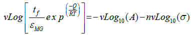
Stress-rupture performance of Mg-based P-MMCs: As seen in Table 4, the time-to-fracture ranged from just a few minutes (0.03 h) at 450°C and 7.5 MPa in pure Mg, to 432 h at 400°C and 5 MPa in the P-MMCs [18]. The time-to-fracture for the composites is lengthened by three orders of magnitude relative to pure magnesium as shown in Figure 9. This significant enhancement in stress-rupture performance of the P-MMCs might be caused by several microstructural factors [18]. They include (i) Orowan strengthening by the presence of nano-sized PDC particles within the magnesium grain matrix, (ii) improved interfacial bonding strength between the PDC particles and the magnesium matrix, and (iii) segregation of PDC particles at the grain boundaries provides significant barrier to grain boundary sliding movement as well as grain boundary growth. The dominant creep mechanisms of the composites are usually determined by the value of stress-exponent (n) and activation energy (Q). As seen in Figure 10 (a), log-log plot of the strain rate vs. stress yields the value of n. The average value for n from these plots is 7 for pure-Mg and 6 for PP800. These values are in line with early data from the literature [52,53].

Figure 9: (a) The creep strain in PP800 specimen does not show softening over the long term, while pure magnesium subjects to softening and premature failure.

Figure 10: (a) The strain rate as a function of stress for pure and dispersion strengthened Mg at 450°C, 400°C and 350°C. (b) A normalized plot showing the best fit for the data to Eq. (6) [18].
 (6)
(6)
The value for Q was obtained by a log-log plot of the left hand side of Eq. (6) vs. stress, using n =7 for pure-Mg and n= 6 for PP800. We sought convergence of the data to a single linear fit for each of the material sets, by attempting different values for Q. The best fit, shown in Figure 10(b), gave the most likely value for Q. In this way, Q was determined to be 215 kJ mol–1 for pure-Mg, and 190 kJ mol–1 for PP800; these values are consistent with data reported [54]. The ductility of PP800 specimens declined from >10% at room temperature to <2.5% in the stress-rupture experiments. This unusual reduction in ductility, which has been called intermediate temperature embrittlement [55,56] is a result of the nucleation and growth of voids at grain boundaries, most often at particles of a second phase [57,58]. The fracture surfaces of pure magnesium and PP800 specimens after stress-rupture test at a temperature of 450°C under 5 MPa are compared in Figure 11. While the pure-Mg sample shows slip bands and cleavage-like fracture [54], the PP800 samples fracture by the nucleation and growth of cavities within the intercrystalline regions. The composites show the classical behavior where the addition of second phase particles to a metal, on the one hand enhances resistance to creep but, on the other, renders the composite susceptible to intermediate temperature embrittlement by the nucleation and growth of voids at grain boundaries [57-60]. The susceptibility to void nucleation depends greatly on the energy of the particle-metal interface. It is possible that the polymer particles provide a higher resistance to nucleation. The polymer composites appear to show lesser tendency for the segregation of the second phase particles to the boundaries. The addition of grain refiners to the metal may further help to alleviate this issue. The conversion of the polymer into the ceramic phase releases hydrogen and small amounts of hydrocarbons [20]. During in-situ processing these gaseous species must migrate to the free surface. This can be an issue, although it does not appear to constrain the production of magnesium-castings. The silicon based precursors can react with the host metal to form silicides. Indeed we have discovered that when the melt it superheated to high temperatures the formation of silicides accelerates. The silicides reduce the ductility of the composites.

Figure 11: The fracture mode in pure magnesium changes to intergranular fracture and lower ductility in PP800 specimen after stress-rupture at 450°C for 5 MPa [18].
AZ91 and AE44 are the most common commercial Mg-alloys that have received a special interest for automobile structural applications. However, they are prone to inferior high temperature creep performance when temperature exceeds 200°C due to coarsening of thermally unstable precipitate via the Oswald ripening mechanism. In order to overcome this coarsening barrier, thermally stable polymer derived SiCNO ceramic dispersoids can be incorporated into these Mg-alloys. Recently, Chelliah et al. [17] synthesized in-situ magnesium matrix composites with three different matrix materials (including Mg, AZ91 and AE44 Mg-alloys) by injecting cross-linked polymer directly into the molten Mg/Mg-alloys, and having it convert to the 2.5 vol% SiCNO ceramic phase using liquid stir-casting method. In-situ chemical reaction took place within the molten slurry tending to produce 42 and 18 vol% Mg2Si crystals in Mg and AE44 matrix composites, respectively but not in AZ91 matrix composite. They discussed microstructural evolution of Mg2Si crystals on the basis of availability of heterogeneous nucleation sites and amount of Al-atoms in the molten slurry. They achieved enhancement in the micro-hardness and yield strengths by factor of four to three as compared to their unreinforced counterparts. They also found that Taylor strengthening as the predominant strengthening mechanism in magnesium and AE44 matrix composites owing to thermal mismatch effect between the reinforced PDC particles and the magnesium matrix.
Dual processing (liquid- and solid state FSP)
Recently, we also fabricated in-situ Mg matrix composites containing Nano-sized SiCNO particles by combining both liquidand solid-state processing routes [16]. Firstly, liquid polymer was injected into the molten Mg at two different temperatures of 700 and 800°C to initiate in-situ pyrolysis. As expected, in-situ pyrolysis aids in the conversion of liquid polymer into sub-micron sized SiCNO particles (mean particle size in the range of 0.5-1 m) and Mg2Si particles. It is experimentally proven here again that formation of Mg2Si phase could be minimized by reducing the pyrolysis temperature from 800 to 700°C. It is well-known fact that most of the polymer derived SiCNO particles were pushed by the solidification front and as a result segregated at the grain boundaries of as-cast composites (mean grain size in range of 50-65 μm) during subsequent solidification process. The issue of grain boundary segregation can be reduced through friction stir processing (FSP) treatment. The severe plastic deformation within the nugget zone is expected to create fragmentation in the sub-micron-sized SiCNO particles leading to Nano-sized particles, and stirring action arising during FSP tool aids in achieving the uniform dispersion of particles throughout the Mg matrix. Therefore, single pass friction stir processing (FSP) of these as-cast composites was performed in order to improve homogeneity in the SiCNO particle distribution, particle refinement (mean particle size of about 200-300 nm), and matrix grain refinement (mean grain size in range of 2.5-3.5 μm). Mechanical properties (hardness, compressive yield stress, ultimate compressive stress, strain to failure and strain hardening exponent) of the dual processed composites were enhanced significantly as compared to their as-cast counterparts. These improvements have accrued due to intense material flow and dynamic recrystallization (DRX) which are the main attributes of FSP.
Solid state processing
Enzo et al. [14] fabricated the Cu-PDC matrix composites by using ball-milling process followed by sintering at elevated temperatures of 1000°C. The morphologies of the ceramic phase can be varied by changing the mechanical alloying process. For example, a TEM micrograph of a continuous phase of 30 vol% of the PDC in copper is shown in Figure 12(a). The data in Figure 12(b) show that micro hardness of the composite increases with the volume fraction of the polymer-derived phase. The most remarkable result is the absence of any loss of micro hardness even after annealing at 950°C (0.9TM) for up to 40 h, which attests to the non-coarsening nature of the ceramic phase. Experiments with copper show the possibility of creating composites that retain their micro hardness to very high temperature confirming the non-coarsening properties of the polymer derived dispersed phase. The copper-PDC composites also have unusual friction and wear properties [61]. This, 20 vol% composite had a lamellar microstructure. The material had the unusual property of a high friction coefficient but a very low wear rate, a good combination of properties for disc-brake applications. Fabrizi et al. [62] reinforced the polymer derived SiCN phase into Ti-6Al-4V matrix by ballmilling process followed by hot-consolidation. They identified the formation of Ti5Si3 and TiC phases within the equi-axed grain matrix after pyrolysis and high temperature sintering. They optimized the volume fraction of PDCs by 10% for enhanced mechanical properties (Vickers hardness and wear resistance) with improved integrity and homogenized microstructure in the Ti-6Al-4V matrix composites. The polymer phase can also be introduced into the copper matrix by friction stir processing, which produces a Nano-scale dispersion of ceramic phase with enhanced mechanical properties. For instance, Ajay et al. [20] achieved a five-fold increase in micro hardness of Cubased in-situ MMCs after introducing polymer precursor by multipass friction stir processing (FSP). This area for P-MMC development is incipient. Another important point here is that the silicon-based precursors are prone to form silicides and nitrides if the host is a transition metal such as Ni, Nb, Ti, and most likely Fe [14]. This problem does not appear to carry harm in the case of Cu and Mg, even though magnesium silicides did form to some degree in the castings [14]. Even if the precursors form silicides, interesting new microstructures [17] and properties are likely to emerge by forming P-MMCs with transition metals. In solid state processing, the gaseous species can accumulate close the ceramic particle that is produced from the pyrolysis of the polymer particle. If this occurs then the strengthening effect of the particles will be compromised. The high temperature properties will be reduced since cavities will nucleate at the particle interface more easily. Systematic experiments where the polymer is retained without being converted into the ceramic have yet to be attempted. It is quite likely that the polymer can react with the metal creating interfaces that are favourable for good mechanical properties. The field of mechanical alloying is well established, but has yet to be applied broadly to create P-MMCs.

Figure 12: High volume fraction copper-PDC composites prepared by mechanical alloying. The polymer derived dispersion is non-coarsening as shown by the absence of softening even after long-term annealing close to the melting point of copper [14].
Summary and Outlook
The simplicity of the polymer precursor approach bodes well for large scale manufacturing. Since most of polymer precursors are generally not inflammable, can be stored in air, do not contain heavy metals and are generally environmentally benign. The liquid injection into molten metal via polymer precursor approach can further simplify the casting process. Various organic precursors can be explored to fabricate magnesium based in-situ MMCs. Binary oxides such as zirconia, titania, and alumina can be obtained from alkoxides. These alkoxides have a high vapour pressure, and therefore must be injected into the liquid magnesium melt in vapor form using a carrier gas (like the Bessemer process for bubbling oxygen).Using poly(titanyl-carbodiimide) precursor, TiCN ceramic phase can be reinforced into the magnesium matrix. TiCN particles are expected to be engulfed by the solidification front owing to high thermal conductivity during casting process. This specific precursor may avoid the necessity of secondary processing techniques and therefore enhancing the mechanical properties of the in-situ MMCs by a single step casting process. Solid state processing of creating composites with copper show the possibility of that they retain their micro hardness to very high temperature confirming the non-coarsening properties of the polymer derived dispersed phase. Stress-rupture data confirmed that creep resistance of Mg-based P-MMCs is one to two orders of magnitude higher than in pure magnesium. This is explained by ability of amorphous SiCNO ceramic phase to impede dislocation motion and resist coarsening at high temperatures. Polymer derived Al-based metal matrix composites can be fabricated using polymer precursor approach. However, aluminium has high solubility with hydrogen gas released during pyrolysis of polymer which eventually produces high porosity in the final castings. Therefore, it is mandatory to remove the hydrogen by de-gassing techniques before solidification. The diversity of materials selection and processing approaches can spur further innovation. The concept of leaving the polymer within the metal without converting it to the ceramic by pyrolysis, which appears to hold promise, would have the added advantage of sidestepping the issue of gas evolution. Though the process needs further development, the promise of the approach is quite evident.
Acknowledgment
This research was supported by the Metals and Nanomaterials program in the Division of Materials Research at the National Science Foundation under Grant No. DMR1105347.
References
- Clyne TW, Withers PJ (1993) An introduction to metal matrix composites. Cambridge University Press, Cambridge, England, UK.
- Lloyd DJ (1994) Particle reinforced aluminium and magnesium matrix composites. Inter Mater Rev 39: 1-23.
- Mortensen A, Iljoon J (1992) Solidification processing of metal matrix composites. Inter Mater Rev 37: 101-128.
- Zhu SM, Nie JF, Mordike BL (2006) Creep and rupture properties of a squeeze-cast Mg-Al-Ca alloy. Metall Mater Trans A 37: 1221-1229.
- Zhao N, Philip N, Xianjin Y (2005) The effect of mechanical alloying on SiC distribution and the properties of 6061 aluminum composite. J Mater Proc Tech 170: 586-592.
- Wilcox BA, Clauer AH (1966) Creep of thoriated nickel above and below 0.5 TM. Trans Metall Soc 236: 570-580.
- Asthana R (1998) Solidification Processing of Reinforced Metals. Trans Tech Publications Ltd., Swizerland.
- Surappa MK (2003) Aluminium matrix composites: Challenges and opportunities. Sadhana 28: 319-334.
- Tjong SC, Ma ZY (2000) Microstructural and mechanical characteristics of in situ metal matrix composites. Mater Sci Eng R Rep 29: 49-113.
- Daniel BSS, Murthy VSR, Murty GS (1997) Metal matrix composites via insitu methods. J Mater Proc Tech 68: 132-155.
- Sudarshan K, Anilchandra AR, Rishi R (2014) Polymer-derived in-situ metal matrix composites created by direct injection of a liquid polymer into molten magnesium. Metal Mater Tran A 45: 551-554.
- Sudarshan MK, Surappa D, Raj R (2008) Nanoceramic–metal matrix composites by in-situ pyrolysis of organic precursors in a liquid melt. Metal Mater Trans A 39: 3291-3297.
- Sudarshan M K, Surappa D, Raj R (2013) United States patent US 8,540,797.
- Castellan E, Ischia G, Molinari A, Raj R (2013) A novel in situ method for producing a dispersion of a ceramic phase into copper that remains stable at 0.9 t m. Metall Mater Trans A 44: 4734-4742.
- Kumar A, Raj R, Kailas SV (2015) A novel in-situ polymer derived nano ceramic MMC by friction stir processing. Mater Des 85: 626-634.
- Chelliah NM, Singh H, Raj R, Surappa MK (2017) Processing, microstructural evolution and strength properties of in-situ magnesium matrix composites containing nano-sized polymer derived SiCNO particles. Mater Sci Engg A 685: 429-438.
- Chelliah NM, Singh H, Surappa MK (2017) Microstructural evolution and strengthening behavior in in-situ magnesium matrix composites. Mater Chem Phy 194: 65-76.
- Chelliah NM, Sudarshan, Lisa K, Singh H, Surappa MK (2017) Stress-rupture measurements of cast magnesium strengthened by in-situ production of ceramic particles. J Mag All.
- Gustafson TW, Panda PC, Song G, Raj R (1997) Influence of microstructural scale on plastic flow behavior of metal matrix composites. Acta Mater 45: 1633-1643.
- Pollock TM, Argon AS (1992) Creep resistance of cmsx-3 nickel-base superalloy single-crystals. Acta Metall Mater 40: 1-30.
- Dieter GE (1986) Mechanical metallurgy, McGraw-Hill, London, Third edition.
- Mukherjee K, Bird JE, Dorn JE (1968) Creep of Metals at High Temperatures. Asm Trans Quart 61: 697-698.
- Ashby MF, Frost HJ (1982) Deformation-mechanism maps. Oxford: Pergamon Press.
- Nadkarni A, Klar E, Scm C (1973) Dispersion strengthening of metals by internal oxidation. U.S. Patent 3: 779,714.
- Brinker J, Jeffrey C, David E, Donald R (1984) Better ceramics through chemistry: symposium held February 1984 in Albuquerque, New Mexico, USA. North-Holland.
- Yajima S, Hayashi J, Omori M, Okamura K (1976) Development of a silicon carbide fiber with high tensile strength. Nature 261: 683-685.
- Zhang H, Pantano CG (1990) Synthesis and characterization of silicon oxycarbide glasses. J A Cer Soc 73: 958-963.
- Soraru GD, Babonneau F, Mackenzie FD (1990) Structural evolutions from polycarbosilane to SiC ceramic. J Mat Sci 25: 3886-3893.
- Mehrotra RC (1988) Synthesis and reactions of metal alkoxides. J Non-Crys Sol 100: 1-15.
- Kroke E, Li YL, Konetschny C, Lecomte E, Fasel C, et al. (2003) Silazane derived and related materials. Mater Sci Eng Rep 26: 97-199.
- Raj R, Riedel R, Soraru GD (2001) Introduction to the special topical issue on ultrahigh temperature polymer derived ceramics. J Am Ceram Soc 84: 2158-2159.
- Pederiva L, Sorarù GD, Latournerie J, Raj R (2002) Pyrolysis kinetics for the conversion of a polymer into an amorphous silicon oxycarbide ceramic. J Am Ceram Soc 85: 2181-2187.
- Saha A, Raj R, Williamson DL (2006) A model for the nanodomains in polymer derived SiCO. J Am Ceram Soc 89: 2188-2195.
- Yu L, Raj R (2015) On the thermodynamically stable amorphous phase of polymer-derived silicon oxycarbide. Sci Rep 5:14550.
- Peña A, Soraru GD, Raj R (2006) Preparation of ultrathin walled carbon based nanoporous structures by etching pseudo amorphous silicon oxycarbide ceramics. J Am Ceram Soc 89: 2473-2480.
- Biasetto L, DeLaPena R, Sorarù GD, Colombo P (2008) Etching of SiOC ceramic foams. Adv Appl Ceram 107: 106-110.
- Soraru GD, Compostrini R, Zera E (2016) Jena p processing and characterization of polymer derived SiOC foam with hierarchical porosity by HF etching. J Ceram Soc J 124: 1023-1029.
- An L, Riedel R, Konetschny C, Kleebe H, Raj R (1998) Newtonian viscosity of amorphous silicon carbonitride at high temperature. J Am Ceram Soc 81: 1349-1352.
- Cross T, Raj R, Prasad SV, Buchheit TE, Tallant DR (2004) Mechanical and tribological behavior of polymer derived ceramics constituted from sicxoynz. J Am Ceram Soc 89:3706-3714.
- Shah SR, Rishi R (2002) Mechanical properties of a fully dense polymer derived ceramic made by a novel pressure casting process. Acta Mater 50: 4093-4103.
- Li Y, Kroke E, Reidel R, Fasel C, Gervais C, et al. (2001) Thermal cross-linking and pyrolytic conversion of poly (ureamethylvinyl) silazanes to silicon-based ceramics. App Organ Chem 15: 820-832.
- Riedel R, Greiner A, Miehe G, Dressler W, Fuess H, et al. (1997) The first crystalline solids in the ternary Si-C-N system. Angew Chem Int Ed Engl 36: 603-606.
- Cross TJ, Prasad VS, Tallant DR, Raj R (2006) Synthesis and tribological behavior of silicon oxycarbonitride thin films derived from poly (ureamethylvinyl) silazane. Int J Appl Ceram Technol 3: 113-126.
- Janakiraman N, Aldinger F (2009) Fabrication and characterization of fully dense Si-C-N ceramics from a poly (ureamethylvinyl) silazane precursor. J Eur Ceram Soc 29:163.
- Janakiraman N, HÄoche T, Grins J, Esmaeilzadeh S (2006) Synthesis and phase evolution of Mg-Si-C-N ceramics prepared by pyrolysis of magnesium-filled poly (ureamethylvinyl) silazane precursor. J Mater Chem 16: 3844-3853.
- Gobind D, Paolo B, Luigi F, Rishi R, Gino M, et al. (2007) Study of the pyrolysis process of an hybrid CH 3 SiO 1.5 gel into a SiCO glass. Vibra Spect 45: 61-68.
- Gervais C, Babonneau F, Dallabonna N, Sorarù G (2001) Sol gel derived silicon boron oxycarbide glasses containing mixed silicon oxycarbide (SiCxO4− x) and Boron Oxycarbide (BCyO3-y) Units. J Am Ceram Soc 84: 2160-2164.
- Sorarù GD, Modena S, Guadagnino E, Colombo P, Egan J, et al. (2002) Chemical durability of silicon oxycarbide glasses. J Am Ceram Soc 85: 1529-1536.
- Zera E, Nickel W, Kaskel S, Sorarù GD (2016) Out-of-furnace oxidation of SiCN polymer-derived ceramic aerogel pyrolized at intermediate temperature (600-800° C). J Eur Ceram Soc 29:423-428.
- Monkman FC, Grant NJ (1956) Proceedings of American Society Testing of Materials 56: 593.
- Ashby MF, Brown LM (1963) On diffraction contrast from inclusions. Phil Mag 8:1649-1676.
- MiliÄÂka K, Čadek KJ, Ryš P (1970) High temperature creep mechanisms in magnesium. Acta Metal 18: 1071-1082.
- Vagarali SS, Langdon TG (1981) Deformation mechanisms in hcp metals at elevated temperatures—I. Creep behavior of magnesium. Acta Metall 29: 1969-1982.
- Tegart WM (1961) Activation energies for high temperature creep of polycrystalline magnesium. Acta Metall 9: 614-617.
- McClintock FA (1968) A criterion for ductile fracture by the growth of holes. J Appl Mech 35: 363-371.
- Rhines FN, Wray PJ (1961) Investigation of the intermediate temperature ductility minimum in metals. ASM Trans Q 54: 117-128.
- Raj R (1978) Nucleation of cavities at second phase particles in grain boundaries. Acta Metall 26: 995-1006.
- Pavinich W, Raj R (1977) Fracture at elevated temperature. Metall Trans A 8: 1917-1933.
- Raj R, Ashby MF (1975) Intergranular fracture at elevated temperature. Acta Metall 23: 653-666.
- Raj R, Ghosh AK (1981) Stress rupture. Metall Trans A 12: 1291-1302.
- Castellan E, Kailas SV, Madayi S, Raj R (2015) Low-wear high-friction behaviour of copper matrix composites dispersed with an in situ polymer derived ceramic. J Trib 137: 024501.
- Fabrizi A, Bonollo F, Colombo P, Biasetto L (2015) In-situ reinforcement of Ti6Al4V composites by polymer derived ceramic phases. Adv Eng Mater 17: 866-8750.