 Spanish
  Chinese
  Russian
  German
  French
  Japanese
  Portuguese
  Hindi
Hindi Review Article, J Electr Eng Electron Technol Vol: 14 Issue: 1
Advanced Fault Detection Technique of Three Phase Induction Motor: Comprehensive Review
B. Hafez Bahgat, Enas A. Elhay and Mahmoud M. Elkholy*
Department of Electrical Power and Machines Engineering, Zagazig University, Zagazig, Egypt
*Corresponding Author:Mahmoud M. Elkholy
Department of Electrical Power and Machines Engineering, Zagazig University, Zagazig, Egypt
E-mail: eaabdelhay@eng.zu.edu.eg
Received date: 03 November, 2023, Manuscript No. JEEET-23-119188; Editor assigned date: 07 November, 2023, PreQC No. JEEET-23-119188 (PQ); Reviewed date: 21 November, 2023, QC No. JEEET-23-119188; Revised date: 22 January, 2025, Manuscript No. JEEET-23-119188 (R); Published date: 29 January, 2025, DOI: 10.4172/2325-9833.1000987
Citation: Bahgat BH, Elhay EA, Elkholy MM (2025) Advanced Fault Detection Technique of Three Phase Induction Motor: Comprehensive Review. J Electr Eng Electron Technol 14:1.
Abstract
This article provides a comprehensive review of fault types and detection methods in induction motors. It discusses the impact of eccentricity faults on motor efficiency, highlighting the use of Motor Current Signature Analysis (MCSA) for static and dynamic eccentricity detection. Additionally, it explores the detection of broken rotor bars through MCSA and sideband components analysis. Stator or armature faults caused by insulation failure are identified using techniques such as Partial Discharge (PD) tests, axial flux component analysis, and statistical process control. The article also addresses bearing faults, categorizing them as ball defects, train defects, outer bearing race defects, and inner bearing race defects, while presenting advanced fault detection methods for three phase induction approaches. motors, including artificial intelligence-based
Keywords: Induction motors; Fault diagnostics; ANN; Fuzzy logic; Analytical methods
Introduction
As electrical machines become more complex, improved fault diagnosis techniques have become essential to ensure secure and reliable operations. Initially, basic safety measures such as overcurrent, over-voltage, and earth-fault protection were employed by manufacturers and users of electrical machines [1-4]. However, timely identification of faults has become critical due to the potential for unexpected machine downtime to disrupt schedules and cause significant financial losses. The primary faults in electrical machines can be categorized as stator defects, improper connections in stator windings, dynamic or static anomalies in the air gap, shorted rotor field winding, and bearing and gearbox failures. Several other diagnostic techniques, such as temperature measurement, infrared recognition, monitoring radio frequency RF emissions, vibration and noise monitoring, chemical evaluation, and acoustic noise analysis, as well as Motor Current Signature Analysis (MCSA) and artificial intelligence and neural network techniques are used to identify faults in electrical machines. In this review article, we will explore the effectiveness of these techniques for fault diagnosis in electrical machines [5,6].
Literature Review
Different fault types and their detection methods
Figure 1 provides an overview of different fault types and detection methods in three-phase induction motors. Faults can lead to reduced efficiency and catastrophic failure. This research focuses on the internal mechanical faults and AI-based methods to detect these faults. We will discuss the advantages, limitations, challenges, and future directions of these detection methods in the following sections.

Figure 1: (a) classifcation of the faults (b) faults diagnosis techniques in IM.
The reviewed article discusses faults in three-phase induction motors: Eccentricity, squirrel cage rotor faults, stator or armature faults, and bearing faults. On Table 1 It explores their causes, detection techniques and effects.
| Fault | Cause | Detection techniques | Effect |
| Eccentricity faults | Static eccentricity caused by ovality of the stator core or improper rotor or stator alignment and dynamic eccentricity resulting from bearing wear, mechanical resonance, or rotational misalignment due to a bent rotor shaft. | (MCSA),vibration analysis, AI-based methods, harmonic analysis at stator terminal voltages, (NFM-IBL), measurement of space and time dependencies of air gap flux. | Vibration and imbalance, increased stress on bearings, shaft misalignment, reduced performance, heat generation, increased noise. |
| Squirrel cage rotor faults (broken bars and end rings) | Broken rotor bars caused by electromagnetic forces, residual tensions, thermal strains, mechanical strains, environmental stressors, and dynamic stresses. | (MCSA),vibration analysis, AI-based methods, Discrete Fourier Transform (DFT), modified Prony's method, online Partial Discharge (PD) test methods, Statistical Process Control (SPC), rectified stator current analysis, artificial intelligence-based stator winding fault estimation in three phase induction motor, asynchronous motors fault detection using Artificial Neural Network (ANN) and fuzzy logic methods. | Increased vibration, altered magnetic fields, overheating, abnormal noise, reduced torque and power output, electrical unbalance, increased current and energy consumption. |
| Stator or armature faults | Stator faults caused by insulation failure, such as phase-to-ground or phase-to-phase faults. | (MCSA), vibration analysis, AI-based methods, online Partial Discharge (PD) test methods, rectified stator current analysis, artificial intelligence-based stator winding fault estimation in three phase induction motor, asynchronous motors fault detection using Artificial Neural Network (ANN) and fuzzy logic methods. | Abnormal current flow, unbalanced magnetic fields, motor overheating, voltage imbalance, reduced motor efficiency, risk of electrical hazards. |
| Bearing faults | Bearing failures due to fatigue, improper lubrication, inadequate placement, contamination, or corrosion. | (MCSA), vibration analysis, AI-based methods, Statistical Process Control (SPC), Empirical Mode Decomposition (EMD), Sample Entropy (SampEn), Hall effect flux sensors. | Increased vibration, excessive noise, reduced efficiency. |
Table 1: The discuses motor faults, causes, detection techniques and effects. and effects.
Eccentricity faults
According to studies conducted by the IEEE-Industry Applications (IAS), the most common failure mechanisms in induction machines are stator faults (38%), rotor defects (10%), bearing defect (40%), and other defects (12%). Among the mechanical faults that can occur in these motors, eccentricity is a notable type, which can be classified as static, dynamic, or mixed in Figure 2 [7]. Static eccentricity is primarily caused by either the stator core's ovality or improper rotor or stator alignment during commissioning. On the other hand, dynamic eccentricity results from bearing wear, mechanical resonance, or rotational misalignment due to a bent rotor shaft. In effect, eccentricity leads to a nonuniform air gap, which results in unstable air-gap voltage and line current. The motor's efficiency decreases as the eccentricity increases, which is evidenced by an increase in average motor current and losses.

Figure 2: Rotor position asbect to satator.
Eccentricity is a dominant factor contributing to failures in threephase induction motors. The resulting vibration and UMF decrease the machine's performance and shorten its working lifetime. Additionally, eccentricity causes mechanical stress on the machine parts, leading to increased bearing wear [8].
In real-world scenarios, it is common for both static and dynamic eccentricities to coexist in induction machines [9]. Even newly built machines have a certain level of static eccentricity due to the production and assembly processes. This results in a consistent Unbalanced Magnetic Pull (UMP) in one direction, which can eventually cause issues such as worn-out bearings or a bent rotor shaft. Dynamic eccentricity can also arise due to these factors, and if left unchecked, these effects can accumulate and lead to a significant machine breakdown, including stator to rotor hub failure. MCSA detects static and dynamic eccentricity and uses the equation (1) to identify relevant frequency components [10].

Where ‘fh’ is the frequency of the shaft's lateral vibration. fr is the rotor frequency. ‘Fs’ is the frequency of the stator vibration. ‘nd’ is the frequency of the bearing's outer race defect. ‘Z2’ is the bearing's characteristic frequency. ‘k’ is a multiple that varies depending on the bearing type and its operating conditions. ‘Υ’ is a factor that accounts for any misalignment between the shaft and bearing.
Models such as Discrete Fourier Transform (DFT) and modified Prony's method are used to identify eccentricity faults. While DFT is easy to use, it is time-consuming and not suitable for dynamic models. Modified Prony's method is an effective alternative and accurately identifies fault characteristic frequency based on stator's power and current results [11].
Squirrel cage rotor faults: Broken bars and end rings
5-10% of induction motor failures are now due to rotor failures, which occur in two types of cage rotors: Cast and fabricated [12,13]. Cast rotors, which are more durable, are now being used in larger machines up to 3000 kW thanks to cast ducted rotors [14]. Fabricated rotors are typically used in larger or specific application machines. Rotor bar and end ring breaking can be caused by electromagnetic forces, residual tensions, thermal strains, mechanical strains, environmental stressors, and dynamic stresses. Cast rotors with faults such as cracked or fractured rotor bars are practically impossible to repair [15,16].
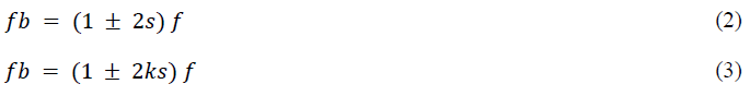
One way to detect broken rotor bars is through MCSA, which identifies sideband components ‘fb’ around the fundamental frequency using equation (2). Broken rotor bars cause a lower sideband, while speed oscillation causes an upper sideband. Multiple sidebands can occur due to broken bars, as demonstrated in with equation (3). Where k=1,2,3,..
A soft sensor for identifying broken rotor bars was introduced using an ensemble learning method based on Dynamic Weighted Majority (DWM) and drift detection with automatic structure evolution using entropy criterion. The fuzzy classifier's membership degree was utilized to calculate entropy for drift detection. Uninsulated rotor cages with strong contact between rotor core and bars may pose difficulty in broken bar identification. Diagnostic tools such as harmonics at stator terminal voltages after motor turn off can also be used [17].
Stator or armature faults
Stator faults, which account for approximately 30-40% of all reported induction motor failures, are often caused by insulation failure. These faults, known as phase-to-ground or phase-to-phase faults, typically start as minor faults that gradually develop into major ones. The failure of stator or armature insulation can be attributed to a number of factors, such as short circuits during motor startup, environmental factors, weak bracing of end windings, loose lamination of the core, cooling system leaks, electrical arcing, and high temperatures in the stator core or winding [18].
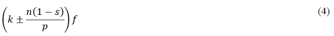
Various techniques can be used to detect these faults. While online Partial Discharge (PD) test methods are highly reliable for large generators and motors with stator windings rated at 4 kV and above, no standardized stator defect detection methods exist for low voltage motors. However, it is possible to analyze the axial flux component of the machine using a large coil tightly wound around the shaft, as demonstrated by [19,20]. Additionally, the fault location can be identified by installing four coils symmetrically in each of the motor's quadrants at a radius approximately halfway between the shaft and the stator end winding. The supply frequency is f, and p is the number of pole pairs. (2p-l), with the slip being s, k=1,3 and n=1,2,3,… can be governed by equation (4).
Okoro found errors causing machine impedance asymmetry resulting in unbalanced phase currents, while attributed it to negative sequence currents. Liu, et al. modeled these imbalances with instrument asymmetries, identifying a "bolted" flaw among 648 turns. Laadjal suggests using the ratio of faulty to healthy positive sequence current as a diagnostic index. Techniques like Statistical Process Control (SPC) and signal processing also aid in identifying stator defects.
Bearing faults
Most electrical machines use ball or rolling element bearings with an inner and outer ring, holding a set of rolling components that rotate by raceways. Even with balanced loads and alignment, fatigue failures can occur, leading to increased vibration and noise levels. External factors such as improper lubrication causing abrasion and heating, inadequate bearing placement leading to raceway indentations, and contamination or corrosion by water or abrasive particles can damage bearings. Detecting bearing-related faults is not well-documented, but they account for 40-50% of motor failures. Bearing faults can cause rotor asymmetry, a symptom of eccentricity, and can be categorized as ball defects, train defects, outer bearing race defects, and inner bearing race defects.
Methods for advanced fault detection
In this section, we will discuss several advanced fault detection techniques that can be used for 3 phase induction motors. These methods include incremental broad learning and non-negative matrix factorization, rectified stator current analysis, measurement of space and time dependencies of air gap flux, artificial intelligence-based stator winding fault estimation in three phase induction motor, and asynchronous motors fault detection using Artificial Neural Network (ANN) and fuzzy logic methods.
A diagnostic methodology for Three Phase Induction Motors (TPIM) faults is proposed using feature extraction, broad learning, incremental broad learning. The system is trained using processed experimental data and can be retrained with incremental wide learning. The study emphasizes the effectiveness of incremental broad learning and suggests improving feature extraction and creating an automatic selection method for incremental nodes in future research. The approach is applicable to other motor diagnostic issues, and increasing feature nodes or inputs may enhance accuracy.
Incremental Broad Learning and Non-Negative Matrix Factorization (NFM-IBL)
TPIMs are susceptible to various faults due to their complex stator and rotor conditions, necessitating a diagnostic system that can quickly and accurately respond. Machine learning-based diagnostic systems have been developed for induction motors, but their complex design requires long training times and complete retraining if inaccurate. To address TPIM faults, we propose using the adaptable Incremental Broad Learning (IBL) method, which includes NMF-IBL and feature extraction methods using Empirical Mode Decomposition (EMD) and SampEn. The proposed TPIM fault diagnostic framework consists of four sub-modules: Data collection and processing, broad learning, incremental broad learning, and structure simplification by NMF as illustated in Figure 3.

Figure 3: Feature extration by IBL and NMF
Data acquisition: The data acquisition sub-module detects four signals: Sound waves and windings A, B, and C currents, referred to as x1, x2, x3, and x4. Since TPIM requires only two stator currents, only three signals (x1, x2, and x3) are used, with a band-limiting filter applied to reduce interference. The sound signal x1 is divided into training, validation, and test datasets obtained through studies.
Data processing: EMD technique is used to analyze raw signals, resulting in three datasets: xk-EMD-Train, xk-EMD-Vali, and xk- EMD-Test. To extract relevant features and eliminate redundant and irrelevant information, the sample entropy (SampEn) statistical approach is employed. The resulting features are normalized to ensure equal contribution, saved as xk-SE-Train, xk-SE-Vali, and xk-SET-est, respectively. Domain Knowledge (DK) attributes are added to facilitate defect detection in sound, winding A current, and winding B current signals. Finally, the preprocessed datasets are renamed as xk- Proc-Train, xk-Proc-Vali, and xk-Proc-Test for further analysis.
Board learning: A wide learning model is trained using the xk- Proc-Train dataset, and its accuracy is evaluated to check if it meets the goal percentage. If not, the model enters the incremental broad learning phase, and the number of enhancement nodes is increased to improve the model's performance.
Incremental broad learning: The IBL sub-module uses xk-Proc- Vali as input and adjusts the number of enhancement nodes dynamically to improve accuracy, but overfitting can occur if the number of nodes is too high. To prevent overfitting, a trial-and-error process is used to determine the optimal number of nodes, N, until the desired validation accuracy is achieved. This is described in a review article.
Structure simplification: The learning system may contain redundant nodes, which can be removed by simplifying the system using low-rank approximations. The IBL structure is compressed using NMF to further reduce system error. If diagnostic accuracy is not within the (TP 0.025) range, additional compression is done through the incremental broad learning sub-module.
Rectified stator current
Stator current analysis is widely used for non-invasive fault detection in induction motors due to its simplicity and minimal hardware and software requirements. However, this method has practical limitations for large induction motors operating at extremely low slip. One major challenge is that fault harmonics close to the fundamental component may be concealed by the fundamental leakage, resulting in delayed detection of the fault until severe damage occurs. In this context, the proposed approach based on rectified motor current analysis offers a simple and effective solution. It is demonstrated that the fault harmonics can be detected at a lower frequency without the fundamental component leakage. The method is easy to implement either through software or hardware, and its effectiveness is experimentally verified in detecting a broken bars defect in a large induction motor.
Measuring the variations of air gap flux with respect to both space and time
This section discusses the importance of condition monitoring for efficient and dependable operation of induction motors. Current diagnostic systems rely on external measurements of current, voltage, vibration, or flux, but this study proposes an online fault diagnostic method that uses an array of Hall effect flux sensors to measure the internal main air gap flux density of induction motors. The proposed method is suitable for specialized motors with high reliability requirements, and the study provides a complete approach for diagnosing induction motor failures. The proposed method can detect issues at an early stage and identify their location and severity. Extensive simulations and a prototype online condition monitoring system based on the national instruments real-time platform confirm the effectiveness of the proposed method.
Faulty stator winding: Stator winding short is a serious problem that can quickly escalate into a catastrophic failure. When a single turn of the stator winding is shorted, it detaches from other turns in the same phase coil, causing a shift in the phase MMF. The isolated turn also carries a loop current that can surpass the rated current and generate excessive heating. The fast identification and localization of stator winding problems are crucial, as shown in an experiment where the temperature of a shorted turn climbed from 60â°C to 120â°C in just 6 seconds. This study proposes a fault diagnosis method that can detect and locate stator winding problems by quantifying the distortion caused by stator shorts directly in the main air gap flux. The proposed method can also pinpoint the precise site of the fault by analyzing the rise in primary wave magnitude during rotation. By using this method, the uncertainties in the time harmonics interpretation can be prevented, and the extensive instrumentation utilized in the investigation can be optimized. Observe the significant increase in the magnitude of the primary wave during the short rotation in Figure 4. This rise can be utilized to locate the exact location of the fault.

Figure 4: Stator winding with a turn-to-turn short.
Eccentricity, both static and dynamic: This article introduces a novel approach to improve critical induction motor instrumentation by employing a Hall effect sensor array around the stator circumference inside the motor air gap. The study focuses on the fundamental theory behind AC motor faults and proposes effective algorithms for detecting stator winding defects, static and dynamic eccentricity, and rotor bar faults. A comprehensive condition monitoring system based on the National Instruments Compact RIO real-time platform has been developed and shown to have excellent fault sensitivity, noise immunity, and dynamic variation tolerance. The article concludes that the suggested approach is ideal for dynamic applications of inverterfed big induction motors with high reliability requirements and has been empirically validated to be effective in fault diagnosis.
Estimation of stator winding fault in three-phase induction motors using artificial intelligence
Detecting faults through multiple optimization techniques remains challenging. To address this, the researchers in this study proposed an intelligent approach using fuzzy logic to detect short-circuit faults in the stator winding of a three-phase induction motor. The fuzzy logic controller analyzes the stator current and indicates the type of motor failure based on the rule base and inference mechanism. The MATLAB-SIMULINK software is used to simulate the healthy and short-circuit fault conditions of a three-phase induction motor as illastrated in Figure 5. The fuzzy logic approach enables fault detection based on available inputs, making it an intelligent method for motor condition monitoring and fault analysis. By detecting faults at an earlier stage, a safer working environment in industries can be ensured.

Figure 5: Membership functions for both input and output variables.
It proposes Artificial Intelligence (AI) algorithms for detecting Interturn Short Circuit (ITSC) faults in three-phase induction motor stators, with a focus on the use of ANN and fuzzy logic systems to reduce the impact of load changes on defect detection. The ANN algorithm is capable of detecting and locating ITSC faults, while the Fuzzy method can diagnose the severity of ITSC defects. The effectiveness of both techniques is validated through simulation and experimental results under ITSC fault and load change conditions.
In order to achieve reliable stator defect detection even under load changes, a combination of ANN and Fuzzy Logic System (FLS) is proposed. Specifically, this research utilizes a feedforward Multi- Layer Perceptron (MLP) neural network trained with the Back Propagation (BP) algorithm to automatically detect and locate ITSC faults. The suggested approach and neural network architecture are illustrated in Figure 5, with the NN's output number set at three to correspond with the three phases of the induction motor where the ITSC fault could potentially occur.
The selection of fault indicators is a crucial step in developing a monitoring and diagnostic system. Interturn Short-Circuit (ITSC) faults in induction motors are often detected using the phase shifts between line current and phase voltage, which provide a wealth of information about the fault. In healthy motors, the phase voltage and line current have identical magnitudes and are displaced by 120 electrical degrees. However, faulty operation can lead to changes in the magnitudes and phase shifts. To investigate the behavior of threephase shifts under various ITSC faults, the faulty stator model proposed in Section II was simulated under different load torques (T=3 and 7 N.m.). Figure 6 shows the three-phase shifts as a function of the number of short-circuited turns under load torque of 5 N.m. The results reveal the influence of load changes on the ITSC fault detection technique.

Figure 6: The characteristics of phase shift due to Interturn Short Circuit (ITSC) faults are observed for (a) phase A, (b) phase B, and (c) phase C under a load torque of 5 N.m.
This study presents two AI-based techniques for robust stator failure detection in the presence of load variations. Artificial Neural Networks and Fuzzy logic are utilized to eliminate the need for an induction motor model during fault detection, resulting in adaptable and easily deployable systems. The ANN technique identifies the faulty phase, while the Fuzzy logic-based detector determines the severity of the problem. These smart techniques have various applications, including alerting the workforce of a dangerous condition and facilitating the repair of a defective stator.
Results and Discussion
Recent developments in induction motor defective models and fault diagnosis methods
As the popularity of artificial intelligence-based condition monitoring systems rises, fault detection systems utilizing Support Vector Machine (SVM), ANN, Nave Bayes classifier, Ensemble, and K-Nearest Neighbors (KNN) have become more prevalent. These systems can detect faults and determine their severity level, but they require extensive data to train and malfunctioning machines are scarce. Numerical methods can simulate faulty conditions that are difficult to test in the field or lab, providing fault data for machine learning algorithms. Accurate Induction Motor (IM) malfunctioning models can minimize harmful testing, lower costs, and validate new fault detection techniques, making them beneficial for training and testing artificial intelligence-based condition monitoring systems. This section covers recent developments in IM models, which are categorized into electrical circuits, magnetic circuits, numerical approaches, and hybrid models, and provides an overview of various fault diagnosis methods as shown in Figure 7.

Figure 7: Recent developments in IM models.
Models featuring coupled circuits
The d-q model is a widely used coupling circuit model that assumes symmetrical motors, linear iron permeability, uniform air-gap, and no tangential induction. These simplifications allow for a fast and accurate mathematical model but are problematic when dealing with faulty equipment. This section discusses recent breakthroughs in coupling circuit models (MCC) and d-q models.
Multiple coupled circuit models: After determining model parameters, the expressions characterizing IM behavior (related to rotor conductors) and requiring stator solving are known as in equations 5,6,7 and 8.
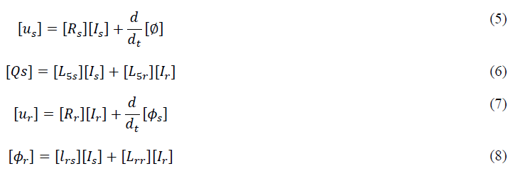
The equations consists of various vectors and matrices, including [Us] for stator voltage, [Is] for stator currents, [Ir] for rotor loop current, [∅s] for stator flux linkage, [Rs] for stator phase resistances, [Lss] for stator windings inductance, and [Lsr] for stator to rotor mutual inductance. Additionally, [Ur] denotes the rotor voltages vector, [Ir] the rotor currents vector, [Ir] the rotor loop currents vector, [∅r] the rotor flux linkages vector, [Rr] the rotor resistance matrix, and [Lrr] the rotor inductance matrix.
d-q model: The implementation of the space vector transformation technique is beneficial for depicting an induction machine with structural symmetry in simulations. By utilizing this method, it is possible to represent such machines using only four differential equations that are linked together. This leads to a reduction in the overall number of equations that are required for simulation purposes. Consequently, the equations that define the stator voltage can be expressed as follows:
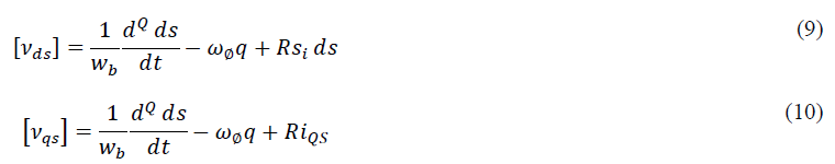
The variables in the aforementioned equation 9 and 10 can be defined as follows: wb refers to the base per-unit electrical speed, while Øds, Øqs, and Ø0s represent the d-axis, q-axis, and zerosequence stator flux connections. The stator resistance is denoted by Rs, and the d-axis, q-axis, and zero-sequence stator currents are respectively represented by ids, iqs, and i0s. Additionally, vdr and vqr refer to the d-axis and q-axis rotor voltages, while φdr and φqr are the d-axis and q-axis rotor flux linkages. Furthermore, ω denotes the perunit synchronous speed, and ωr refers to the per-unit mechanical or rotational speed.
Models based on Magnetic Circuits (MEC)
In this approach, discrete winding distributions, stator and rotor slotting, and magnetic material saturation-induced saliency effects related to space harmonics are taken into account. The nodal magnetomotive forces [F] are connected to the reluctances [R] in the equation 11, which represent the fluxes of the rotor and stator [Ø].

In conclusion, the MEC-based framework has demonstrated high precision in predicting machine performance across diverse operating points, load conditions, and even unbalanced excitation and faulty conditions. Its accuracy and computational efficiency make it an ideal alternative between the standard lumped parameter models and FEMbased approaches. The MEC technique has also proven effective in modeling a range of induction motor faults.
Models based on mathematical procedures (FEM)
By utilizing the machine's actual magnetic and geometric properties, this technique calculates the distribution of the magnetic field. In general, faulty induction motor models are created in 2D, which offers excellent accuracy in terms of magnetic phenomena. However, these models do not consider the rotor's skewing behavior or the end rings, and the connection of the rotor bars is typically addressed through an ideal current source in the electrical circuit. The magneto-dynamic field equation for a standard induction motor in 2D is defined as follows:

In the given equation 12, (A)→represents the magnetization potential, Az is the z-component of the magnetic vector potential, J0 refers to the applied density current source, v→ represents velocity, σ is the electric conductivity, and v represents permeability.
Models with hybrid components
Recent research suggests that combining FEM and analytical methodologies can generate models with FEM level accuracy, which can be executed in real-time simulators. A hybrid model based on the d-q method and finite element analysis has been proposed to model short circuit defects in IM drives. In this model, sparse identification is utilized to minimize the number of FEM simulations needed to compute the IM coupling parameters. FEM is used to solve the entire geometry of the IM, and the coupling parameters are then imported into the machine's analytical model. The sparse identification method is effective in obtaining a defective IM model while minimizing the number of FEM simulations needed, thus reducing computing expenses by over 99.9%. However, the full FEM analysis is still required for each failure scenario, resulting in extensive simulation periods and expensive computational costs. TSFEM-based models require lengthy simulation times for small simulated spans, whereas hybrid models require approximately 25 minutes. Even when the time to execute one simulation is factored in, the time savings exceed 98%.
Conclusion
In conclusion, fault diagnosis techniques for electrical machines have evolved to ensure secure and reliable operations. The review article explored various diagnostic techniques that is summrized on Table 6, including temperature measurement, infrared recognition, vibration analysis, Motor Current Signature Analysis (MCSA), and artificial intelligence and neural network techniques. The article highlighted the importance of fault detection methods for different types of faults, such as eccentricity, rotor faults (broken bars and end rings), stator or armature faults, and bearing faults. Advanced fault detection methods, including incremental broad learning and nonnegative matrix factorization, rectified stator current analysis, measurement of space and time dependencies of air gap flux, and artificial intelligence-based methods, were discussed. These techniques offer effective solutions for fault detection, enabling timely identification of faults to prevent unexpected machine downtime and financial losses. Further research and development in these areas are necessary to enhance fault diagnosis capabilities for electrical machines.
References
- Strangas EG, Clerc G, Razik H, Soualhi A (2022) Fault diagnosis and prognosis for reliability enhancement. In Fault Diagnosis, Prognosis, and Reliability for Electrical Machines and Drives: IEEE, pp. 345-414.
- Bednarz SA, Dybkowski M, Wolkiewicz M (2018) Compensation of the rotor faults in the vector controlled induction motor drive using parameter estimator. In2018 International Symposium on Electrical Machines (SME), pp. 1-5.
- Dorrell DG, Makhoba K (2017) Detection of inter-turn stator faults in induction motors using short-term averaging of forward and backward rotating stator current phasors for fast prognostics. IEEE Transactions on Magnetics 53: 1-7.
- Nandi S, Ahmed S, Toliyat HA (2001) Detection of rotor slot and other eccentricity related harmonics in a three phase induction motor with different rotor cages. IEEE Transactions on Energy Conversion 16: 253-260.
- Almounajjed A, Sahoo AK, Kumar MK, Bakro MW (2021) Condition monitoring and fault diagnosis of induction motor-an experimental analysis. In2021 7th International Conference on Electrical Energy Systems (ICEES), pp. 433-438.
[Crossref]
- Corral-Hernandez JA, Antonino-Daviu JA (2018) Thorough validation of a rotor fault diagnosis methodology in laboratory and field soft-started induction motors. Chin J Electr Eng 4: 66-72.
- Liu Z, Zhang P, He S, Huang J (2021) A review of modeling and diagnostic techniques for eccentricity fault in electric machines. Energies 14: 4296.
- Bouchareb I, Lebaroud A, Cardoso AJ, Lee SB (2019) Towards advanced diagnosis recognition for eccentricities faults: application on induction motor. In2019 IEEE 12th international symposium on diagnostics for electrical machines, power electronics and drives (SDEMPED), pp. 271-282.
- Polat A, Ertugrul YD, Ergene LT (2015) Static, dynamic and mixed eccentricity of induction motor. In2015 IEEE 10th international symposium on diagnostics for electrical machines, power electronics and drives (SDEMPED), pp. 284-288.
- Garcia-Calva T, Morinigo-Sotelo D, Fernandez-Cavero V, Romero-Troncoso R (2022) Early detection of faults in induction motors and mdash: A review. Energies 15: 7855.
- Park Y, Choi H, Lee SB, Gyftakis K (2019) Flux-based detection of non-adjacent rotor bar damage in squirrel cage induction motors. In2019 IEEE energy conversion congress and exposition (ECCE), pp. 7019-7026.
- Lashkari N, Azgomi HF, Poshtan J, Poshtan M (2015) Robust stator fault detection under load variation in induction motors using AI techniques. In2015 IEEE International Electric Machines and Drives Conference (IEMDC), pp. 1446-1451.
- Jerkan DG, Reljic DD, Marcetic DP (2017) Broken rotor bar fault detection of IM based on the counter-current braking method. IEEE Transactions on Energy Conversion 32: 1356-1366.
- Lee HJ, Im SH, Um DY, Park GS (2017) A design of rotor bar for improving starting torque by analyzing rotor resistance and reactance in squirrel cage induction motor. IEEE Transactions on Magnetics 54: 1-4.
- Thomson WT, Culbert I (2017) MCSA Case Histories—Diagnosis of Cage Winding Defects in SCIM s Fitted with End Ring Retaining Rings. InCurrent Signature Analysis for Condition Monitoring of Cage Induction Motors: Industrial Application and Case Histories, pp. 147-172.
- Trujillo-Guajardo LA, Rodriguez-Maldonado J, Moonem MA, Platas-Garza MA (2018) A multiresolution Taylor–Kalman approach for broken rotor bar detection in cage induction motors. IEEE Transactions on Instrumentation and Measurement 67: 1317-1328.
- Bensic T, Varga T, Barukcic M, Krizanic S, JerkovicStil V (2019) Identification of Inertia Constant from Induction Motor Load Transient. In2019 International IEEE Conference and Workshop in Óbuda on Electrical and Power Engineering (CANDO-EPE), pp. 55-60.
- Terron-Santiago C, Martinez-Roman J, Puche-Panadero R, Sapena-Bano A (2021) Low-computational-cost hybrid FEM-analytical induction machine model for the diagnosis of rotor eccentricity, based on sparse identification techniques and trigonometric interpolation. Sensors 21: 6963.
[Crossref] [Google Scholar] [PubMed]
- Panagiotou PA, Arvanitakis I, Lophitis N, Antonino-Daviu JA, Gyftakis KN (2019) A new approach for broken rotor bar detection in induction motors using frequency extraction in stray flux signals. IEEE Transactions on Industry Applications 55: 3501-3511.
- Naha A, Samanta AK, Routray A, Deb AK (2016) A method for detecting half-broken rotor bar in lightly loaded induction motors using current. IEEE Transactions on Instrumentation and Measurement 65: 1614-1625.

