 Spanish
  Chinese
  Russian
  German
  French
  Japanese
  Portuguese
  Hindi
Hindi Review Article, J Electr Eng Electron Technol Vol: 10 Issue: 11
Analysis and Study of Different Types of Power Converters
Kummari Venkateswaramma1, B.Vishala1, Sabbi Vamshi Krishna2, Sandip Swarnakar3*
1Department of Electrical and Electronics Engineering, G. Pullaiah College of Engineering and Technology,Kurnool, Andhra Pradesh, 518002, India
2Department of Electronics and Communication Engineering, Ravindra College of Engineering for women, Kurnool, Andhra Pradesh, 518002, India
3Department of Electronics and Communication Engineering, G. Pullaiah College of Engineering and Technology, Kurnool, Andhra Pradesh, 518002, India
*Corresponding Author: Sandip Swarnakar
Department of Electronics and Communication Engineering, G. Pullaiah College of Engineering and Technology, Kurnool, Andhra Pradesh, 518002, India
Tel: 9045137227
E-mail: drsandipece@gpcet.ac.in
Received: August 07, 2021 Accepted: November 16, 2021 Published: November 29, 2021
Citation: Sandip Swarnakar (2021) Analysis and Study of Different Types of Power Converters. J Electr Eng Electron Technol 10:11.
Abstract
Owing to its peculiar physical properties, Titanium Dioxide (TiO2) has found various applications and been an interactive material for research in the field of semiconductor physics. To study the crystallographic nature of prepared Fe/TiO2 and Ni- Fe/TiO2, X-ray Diffraction (XRD) study was done. The result shows that both pure and doped TiO2 samples were anatase phase with the absence of diffraction peaks of Ni or Fe. The Scanning Electron Microscopy (SEM) images revealed that the particle morphology was altered by dopants incorporation which acted as nucleation sites. The dielectric properties and electrical conductivity for TiO2 and TiO2 loaded Fe, Ni and Ni- Fe composition within the temperature range 25°C-110°Cand over the frequency range (100 Hz-0.3 MHz) were also carried out. The values of dielectric constant and dielectric loss decrease with increasing frequency. The dielectric permittivity for Fe/TiO2 exhibits relatively lower dielectric constant than Ni- Fe/TiO2. A relaxation peak has been recognized and shifted to higher frequency with increasing temperature. The ac conductivity was found to increase with frequency which could be related to the hopping conduction process. The activation energy Ea for Fe/TiO2 was higher than Ni-Fe/TiO2 and decreased with increasing frequency
Keywords: Fe doped TiO2; Ni-Fe doped TiO2; AC conductivity; Dielectric properties; Activation Energy
Introduction
The electricity demand is growing recently, as many countries are prepared instead of using exact sources of other energy sources [1-3]. Generating energy produces no emissions from the fuels and reduces pollutions. The benfit of shifting to renewable energy sources are no expense, and simple access [4-6]. Thermal power plants are contributed to increase around 75–82 percent of thermal emissions, which can produce undesirable changes in the environment [7-9]. The world’s energy is increasing, especially in developed countries. Global energy consumption has tripled within the last 40 years and is growing to triple within the next 20 years [10-12].
The main requirement of energy converters, is converting a fixed to a variable DC voltage source is important for several industrial applications. A DC converter is analogous to an AC transformer with a constantly changing turn’s ratio within the perspective of a DC equivalent. It functions as a transformer like a step-down or step-up converter. If the switches are BJT, MOSFET, or IGBT must perform pulse width modulation (PWM) at a specific frequency to be controlled [13-15]. Buck converter, Boost converter, Buck-Boost converter, Cuk converter, Forward converters are the examples of several types of converters. The normal scheme uses the input of the converter to offer power is transferred to the load from each energy source [16-18]. Unlike AC, DC is almost impossible to intensify or step down without the necessity for expensive machinery. The converters are high-end chopper circuits with credible and high-power rated power electronics components and switches that change the DC output from a given DC input. They are often to control voltage and power flow during the transmission process [19-20].
The traditional boost converter is used in power system for high step-up applications with large current ripples, which create conduction losses. Due to high inductance values, the majority of the converters have high input current. To limit these we can increase the switching frequency and it reduces the voltage stress across the switches. Soft switching frequency is required to reduce switching losses and increase efficiency [21-23].
Several researchers employ the Single-ended primary-inductor converter (SEPIC) and the modified SEPIC converter for high static gain applications [24-25]. The SEPIC converter has a double static gain value and a switching voltage that is half that of a conventional boost converter. The presented technique features a lower inductor input inrush current, a faster settling time, and shorter output voltage, peak duration when compared to conventional converters [26-27].
The structure of the paper is summarized below; Section 2 provides an overview of different types of DC-DC converters and compares the advantages and disadvantages of boost and SEPIC converters. Section 3 provides the converter's specification and analysis, as well as a brief overview of the converter. Section 4 of the paper summarizes the importance of the converter.
Review on various sorts of converters
Several DC-DC converters, both isolated and non-isolated converters are analyzed. Various fly-back topologies can offer improved efficiency, decreased switching losses, reduced voltage and current pressures on the switches in the isolated converter. Many non-isolated modifier cell converters have a high voltage gain, which can be a competitive solution for many DC-DC converter topologies [27-28]. The whole study describes all DC-DC converters by using photovoltaic (PV) systems. The below sections contain the various papers studied, summarized, and compared based on some significant parameters like duty ratio, response time, size, etc.
Implementation of DC-DC converters by using non-isolated converters
Many converters are non-isolated converters for high-quality power generation. As a result, high electrical voltages are vulnerable and loud [27-30]. Below is a review and comparison of the implementation of numerous converters that use non-isolated converters.
Author in Ref. [1], improved modeling methods for steady state and dynamic systems are being developed, for circuit design, power, or to improve the system's stability and performance. This paper presents new circuit analyzer software which helps to design and analysis of electronic circuits. DC-DC converter types are useful to model and analyse the converters.
In the article Ref. [2], automobile manufacturers have been developing fuel cell-powered hybrid electric vehicles, which decrease pollutants and boost fuel efficiency. This document offers information about the various topologies and classifications of DC-DC converters. It connects the cell to engine controllers. The temperature and the loading level of your vehicle increased since the characteristics changed in electric automobiles.
Author in Ref. [3], the MPPT is a technique, used to measure the panel output voltage. A Sepic or Cuk converter is a new method to track the MPPT of a solar panel. This approach can reduce the need for 1) digital converter parameter value, 2) advanced panel output power mathematical calculations, and 3) approximation output panel characteristics.
Author in Ref. [4], the MPPT of a PV generator differ with solar insulation & it has a nonlinear – features. A fuzzy controller, a feed-forward MPPT scheme for the coupled-inductor and inter-leaved-boost-converter-fed PV system, is established. The converter has lower switch current stress and higher performance.
Author in Ref. [5], the chosen architecture contains two conversion stages, DC-AC and AC-DC, and isolates them by using a high-frequency transformer with an input voltage range from 15 to 30 Vdc. These features are provided by employing a prototype with a power rating 700 W and switching frequency 20 kHz.
In the article Ref. [6], batteries (B) and ultra-capacitors (UC) are utilised to store more energy from the device when it is required. The major power source in this model will be an internal combustion engine with a permanent magnet synchronous generator.
Author in Ref. [8], introduces a three-phase PV with three-level MPPT. The three-level boost converter is controlled and monitored by the MPPT. This converter optimised the reverse recovery losses and improves the total power output.
Author in Ref. [9], the UC is used in energy storage devices in vehicle applications. Combinations of UC and advanced batteries are likely to be advantageous in future. Batteries are built, according to our requirement.
Author in Ref. [10], solar irradiation conditions are primary causes of low energy yield in PV systems. Non-uniform conditions result in different local MPPT on the power voltage curve. Since the global MPPT will shift over time, since the voltage window and its location, is influenced by shading patterns, identifying the global operating point under partially shaded conditions is difficult.
| Ref. No. | Structure | ControlParameters | Components | Advantages&Limitations |
|---|---|---|---|---|
| [13] | All-non-isolated converters related to dc-dc converter.(Mummadi Veerachary, 2011)  Fig 1: Schematic of Proposed Buck-Converter Fig 1: Schematic of Proposed Buck-Converter |
Vi=Vi-V0D=V0/VDuty cycle, Voltage & Current | Diode =1Inductor =1Capacitor =1Switch =1Source =1Pulse generator =1Load =1 | Efficient Power conversion extends battery life and Efficiency is poor for high gain |
| [7] | All-non-isolated converters related to dc-dc converter.(Jung-Min Kwon , 2008) 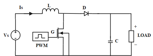 Fig 1: Schematic of Proposed Boost-Converter Fig 1: Schematic of Proposed Boost-Converter |
Vi=(1-D)V0 VC=V0/DVoltage and Current | Diode =1Inductor =1Capacitor =1Switch =1Source =1Pulse generator =1Load =1 | High Output Voltage and Large output capacitor required. |
| [15] | All-non-isolated converters related to dc-dc converter.(Kashif Ishaque , 2012) 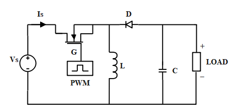 Fig 1: Schematic of Proposed Buck- Boost Converter Fig 1: Schematic of Proposed Buck- Boost Converter |
dIL/dt= Vi/LD=V0/ V0-ViVoltage and Current, Duty cycle and Irradiance & Temperature | Diode =1Inductor =1Capacitor =1Switch =1Source =1Pulse generator =1Load =1 | Efficiency of regulating the output voltage is high and Complexity in Circuit. |
| [3] | All-non-isolated converters related to dc-dc converter.(Henry Shu-Hung Chung, 2003)  Fig 1: Schematic of Proposed Cuk-Converter Fig 1: Schematic of Proposed Cuk-Converter |
VC=V0/DV0/Vi= D/1-DDuty Cycle and Voltage & Current | Diode =1Inductor =1Capacitor =1Switch =1Source =1Pulse generator =1Load =1 | Continuous input and output current, efficient voltage regulation and High current stresses on the switch |
| [3] | All-non-isolated converters related to dc-dc converter.(K. K. Tse , 2003) 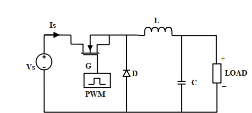 Fig 1: Schematic of Proposed SEPIC-Converter Fig 1: Schematic of Proposed SEPIC-Converter |
VC=V0/DV0/Vi= D/1-DDuty Cycle and Voltage & Current | Diode =1Inductor =2Capacitor =2Switch =1Source =1Pulse generator =1Load =1 | Continuous input and output current, efficient voltage regulation and High current stresses on the switch |
Table1: Types of converters using non-isolated converters and their advantages
Implementation of DC-DC converters by using isolated converters
Author in the paper Ref. [11], plug-in hybrid electric vehicle (PHEV) will be improved by a spinning solar panel (SP). Traditionally, putting a PHEV with SP on the roof of an EV has been more difficult. Because the available space on the vehicle's roof is insufficient, a rotatable structure can monitor the sun utilizing mechanical Petri-net (PN)-based (MPPT) control.
In the paper Ref. [12], solar photovoltaic is accomplished through impedance matching by using a dc-dc converter and MPPT via the incremental conductance technique. To achieve stability and dynamic control, we are using continuous conduction.
In the paper Ref. [13], the high-gain interleaved boost-derived converter is introduced and compared to the basic boost converter, which provides modularity, lower voltage and current ratings for various circuit components.
Author in the paper Ref. [14], the power delivered in solar PV systems contains multiple PV modules is feeding a similar load. A novel MPPT algorithm that incorporates a particle swarm optimization (PSO) technique to resolve this challenge. Due to these it optimises the cost, and simple to implement.
In the paper Ref. [15], the impedance of PVA, MPPT will become unstable; developing optimal damping that is appropriate for all solar insulation is a difficult task. The converter can monitor MP under the boundary conditions. The suggested topology is different from that of a buck converter with input filter.
Author in Ref. [16], based on a modified PSO algorithm, this research provides an improved MPPT method for PV systems. Once the maximum power point (MPP) is reached, the method's major benefit is to minimize steady-state oscillation.
In the article Ref. [17], the design and modelling of a 12 kHz transformer and battery capacity of 7.75 kW complete-bridge dc-dc converters are described. For isolation purposes, high-frequency transformers are used. The circuit topologies are reviewed for battery charging and discharge applications employing only one transformer and bi-directional converter.
Author in paper Ref. [18], with the help of switching current and the voltage on the switch & several other factors are influencing to design the simple dc-dc converter. This study discusses DC-DC converter modeling. Two typical varieties of converters are worn for testing the suggested modeling approach. This technique is used to design isolated DC-DC converters.
Author in paper Ref. [19], this study discusses the current improvements in dc-dc converters, which are constructed based on two simple converters: the buck converter and the boost converter. Converters with high performance, high profit, and fast response objectives and produced.
Author in the paper Ref. [20], the converters are employed in power supplies, photovoltaic systems, renewable energy systems, and industrial applications. Switching failure occures in dc-dc converters, and it affects the converter's performance and power density. To tackle the switching problem, the author developed new soft-switching PWM converter topologies.
Author in the paper Ref. [21], the semiconductor switch dead time on the operation of a dc-dc converter used in HEV. The study were utilized to create a control method that uses gain scheduling and time presetting to handle the converter current's nonlinear responseo t duty cycle changes.
Author in the paper Ref. [22], the two-stage controller uses the average model of the system, a -modulator is realistic. Finally, they are obtained to check the control efficiency of this strategy.
Author in the paper Ref. [23], MPP for stand-alone PV systems are employing fuzzy logic control (FLC). The FLC is simple to use and it is not necessitate thorough an understanding of the system's concept. Simulation results are compared by using the standard perturbation and observation (P&O) technique to demonstrate the effectiveness of the FLC under steady-state.
Author in the paper Ref. [24], power electronics applications in fuel cell systems, which comprise a variety of topologies combinations of DC converters and AC inverters utilized mostly in stationary applications.
Author in the paper Ref. [25], the converter design techniques implemented in this project make this statement more feasible with a controlled output voltage of 3 volts and a standard supply voltage of 1-3 volts, this DC-DC converter is a step-up converter. For the converter, PWM is used. There is a 1mV overshoot above the ideal output voltage.
The table below illustrates all sorts of converters by employing isolated converters. The transformer turns ratio is calculate circuit characteristics such as an inductor, capacitor, and resistor values. We can build circuits such as fly-back, forward, half-bridge, push-pull, and full-bridge converters by knowing the values.
| Ref. No. | Structure | Control Parameters | Components | Advantages & Limitations |
|---|---|---|---|---|
| [52] | All- isolated converters related to dc-dc converter.(R. Kavin , 2019) 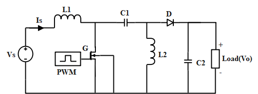 Fig 1: Schematic of Proposed Fly back-Converter Fig 1: Schematic of Proposed Fly back-Converter |
V0=N2/N1 VIN.1-DV0=D/1-D Voltage and Current | Diode =1Capacitor =1Switch =1Source =1Pulse generator =1Load =1 | voltage rating on secondary components low and more ripple current |
| [54] | All-isolated converters related to dc-dc converter.(Sachin kale , 2019) 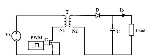 Fig 1: Schematic of Proposed Forward-Converter Fig 1: Schematic of Proposed Forward-Converter |
V0=NS/NP VS.DV0=D/1-D Voltage & Current and Temperature | Diode =2Inductor =1Capacitor =1Switch =1Source =1Pulse generator =1Resistive Load =1 | Due to much larger magnetizing inductance and Increased cost, transformer of the forward converter does not store energy. |
| [55] | All-isolated converters related to dc-dc converter.(Sachin kale , 2019) 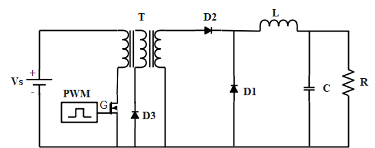 Fig 1: Schematic of Proposed Push - pull-Converter Fig 1: Schematic of Proposed Push - pull-Converter |
V0=NS/NP VS.DLf = (1-2D) R/4f Voltage & Current | Diode =2Inductor =1Capacitor =1Switch =2Source =1Pulse generator =2 | Robust, Capable of dealing with disturbances and more sensitive to disturbances. |
| [57] | All-isolated converters related to dc-dc converter.(Sachin kale , 2019) 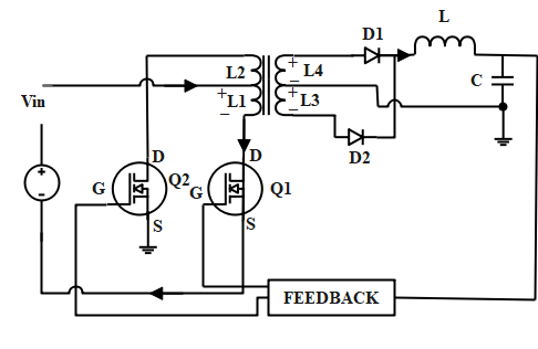 Fig 1: Schematic of Proposed Half-bridge –Converter Fig 1: Schematic of Proposed Half-bridge –Converter |
V0=NS/NP VS.D/2Lf = (1-2D) R/2f Voltage & Current | Diode =2Capacitor =2Switch =2Source =1Resistive load =1 | It requires four diodes, two of which conducts alternative half cycles. This creates a voltage drop of 1.5 V. |
| [59] | All-isolated converters related to dc-dc converter.(Sachin kale , 2019)  Fig 1: Schematic of Proposed Full-bridge –Converter Fig 1: Schematic of Proposed Full-bridge –Converter |
V0=NS/NP VS.DLf = (1-2D)/4f Voltage & Current | Diode =2Inductor =1Capacitor =1Switch =4Source =1Pulse generator =4Resistive Load =1 | Slower that repeaters due to filtering and Reduce collisions |
Table2: Types of converters using isolated converters and their advantages
Comparison of all types of converters by using isolated and non-isolated converters
Boost converters are employed in rectifier circuits with power factor adjustment, and as a result, the output voltage is regulated. Buck-boost or Cuk converters are used to increase the controllable voltage range [32]. Several all types of converters are implemented by using linear non-isolated and isolated converters has been studied summarized and compared in below sections.
Comparability of DC-DC converters
Author in the paper Ref. [26], presents an analysis of prominent strategies for high step-down dc-dc voltage conversion. Each technique/topology has circuit diagram and key points are discussed. An interleaving converter reduces ripples, and a quadratic, tapped, or switched capacitor avoids a small duty cycle for high step down. A multilevel converter is good for minimizing switching tension, and coupled inductors can reduce ripples.
Author in the paper Ref. [27], for this entire paper, many bridges have been designed for efficiency and cost of DC-DC Buck-Boost converters, and losses are comparable. Traditional PI and FLC have been used for BLDC speed control studies. The output of classical PI and FLC is compared under varying reference speed and load disturbances for different parameters in the BLDC motor drive.
In the article Ref. [28], the primary consideration for electric vehicles (EV) is range. The most essential factor in determining an EV range is the battery capacity. Because batteries are the most expensive component of an EV, other considerations such as weight, aerodynamic drag coefficient, and motor size should be made.
Author in the paper Ref. [29], solar - PV, wind, fuel cell, battery, super capacitor, and other green energy sources are highly recommended in HEV applications. Power converters are required to incorporate these renewable energy sources into the vehicle system.
In the article Ref. [30], the converter has a 15-volt input voltage and a 150-volt output voltage with 100-watt output power. The efficiency of the converter was 92.5 percent, which was higher than the other converter models.
Author in the paper Ref. [31], the converter is required to achieve high efficiency and true soft switching, which is critical for high voltage electric vehicles. MATLAB and MULTISIM were used to simulate and model the device in this analysis.
Author in the paper Ref. [32], the power grid is capable of maximizing the renewable energy sources while maintaining high levels of sustainability, performance, and grid stability. The study has two objectives: first, it examines a DC nano grid that is ideal for tiny energetic clusters such as residential or commercial buildings and incorporates solar arrays, fuel cells, electric car charging stations, and loads, and second, it presents a solution to this problem.
In the paper Ref. [33], fuel cells use a lot of energy and generate it directly from hydrogen and oxygen at a low voltage. Finally, the paper provides some guidance to assist the designer in determining which converter topologies are most suitable in terms of compactness, performance, and cost.
In the paper Ref. [34], the proposed energy management system's goal is to concentrate on the advantage of super capacitor properties and improving battery lifetime and device performance. The energy management system's job is to generate battery reference current.
Author in the paper Ref. [35], this paper discusses the topologies of ZVS (Zero-Voltage-Switching) and ZCS (Zero-Current-Switching) resonant DC-DC converters. It indicates the topologies of DC-DC converters can be used to create numerous equivalent converter topologies. This fact is used to create DC-DC converter topologies that are ideal for high-frequency operation.
| Converter | Ref. No. | Year | Control parameters | Applications |
|---|---|---|---|---|
| Buck-Converter | [12] | 2014 | Duty cycle | Fuzzy MPPT |
| [14] | 2010 | Current | Variable inductance | |
| [16] | 2003 | Voltage and Current | P&O | |
| Boost-converter | [18] | 2008 | Voltage | MPPT |
| [19] | 2011 | Voltage and Current | P&O | |
| [20] | 2011 | Voltage | FLC with ANN | |
| Buck-Boost converter | [21] | 2012 | Duty cycle | PSO |
| [22] | 2009 | Irradiance and Temperature | ANN-Fuzzy logic controller | |
| [23] | 2012 | Voltage | ANN | |
| [25] | 2010 | Voltage and Current | P&O | |
| [28] | 2020 | Voltage and Current | MPPT | |
| Cuk converter | [32] | 2010 | Voltage and Current | Maximum Power Point Tracking Technique for Solar Panels |
| [33] | 2011 | Voltage | Fuzzy logic control system for photo voltaic | |
| [35] | 2012 | Voltage and Current | MPPT | |
| SEPIC converter | [36] | 2013 | Voltage and Current | Photo voltaic Characteristics |
| [38] | 2009 | Voltage | MPPT tracking for PV panels | |
| [40] | 2012 | Voltage | Fuzzy logic control system for photo voltaic | |
| [42] | 2010 | Voltage and Current | Energy Storage | |
| Zeta converter | [45] | 2013 | Voltage and Current | Hybrid PV-Wind Micro grid |
| [46] | 2010 | Voltage and Current | Photo voltaic Battery Charger | |
| [48] | 2011 | Voltage | Input impedance matching |
Table3: Various types of converters by using the control parameters and applications
Types of DC-DC Converters
DC-to-DC converter is a class of power converters and it is an electric circuit, which converts a one magnitude of voltage level to another magnitude of voltage level, by keeping the input energy for the moment and then releases that energy to the yield at a different voltage [33-34]. All types of converters are shown in Fig 1. DC-DC converters are categorized into Linear mode regulator and Switching mode regulators.

Figure 1: Types of power converters
Linear mode regulator
Voltage regulators (VR) are almost all-electronic hardware. A VRs job is to maintain the constant voltage on the regulator's output while the input voltage is variable. The fundamental benefit of a linear mode regulator is produces less noise and boosts efficiency [35]. VR are classified in series and shunt regulators.
Series voltage regulator
The VR is a voltage-controlled circuit, as the name implies. The output of the voltage is unaffected by changes its load current or temperature. In almost all electronics or households, voltage regulators are available to stabilize the voltage and most of the appliances such as TV, refrigerator, machine etc. The Series Voltage Regulator, are also known as Series Pass Regulators are Shown in Fig 2, it seems to be a member of the Linear Voltage Regulator [36-38]. Variable element is connected in series with the load and maintains a linear voltage. By changing the resistance value the voltage drop across the series element can be changed.

Figure 2: Schematic representation of a series voltage divider
Shunt Voltage Regulator
A shunt VR works by supplying a variable resistance channel from the supplied voltage to the ground.
The shunt regulator has been diverted by the load due to the current flowing in it and is now it is flowing uselessly to the ground. Shunt VR is less efficient, less complicated and it consists of a voltage reference element is as sown in Fig 3 [39-40]. It is used as a low-power applications and it is taken as a reference.
Table 4 compares series and shunt voltage regulators based on their connection, control components,stability,andefficiency.

Figure 3: Schematic representation of a shunt energy push button
| Comparison | Shunt regulator | Series regulator |
|---|---|---|
| Connection | Shunt voltage regulator is connected in parallel /shunt with the load. | Series voltage regulator is connected in series with the load. |
| High Load currents | It has good voltage regulation even at high load currents | It does not have an effective voltage regulation at high load currents |
| Suitability | The regulator is suitable for light loads. | The regulator is suitable for heavy loads. |
| Output DC | In this regulator, the output DC voltage is constant. | In this regulator, the output DC voltage is not constant. |
| Control Element | The control element has to bear the load voltage across it. Therefore, it is a high voltage low current device. | The control element has to carry the load current. Therefore, it is high current low voltage device. |
| Efficiency | It has good efficiency for low load current. | It has good efficiency for high load currents. |
Table4: Comparison of shunt and series voltage regulators
Switching mode regulator
Switching regulators convert one voltage to another by momentarily storing energy and then releasing it to the output as a different voltage. Switched mode power supply, switching regulators, and switching converters are all terms used to describe DC to DC converters.
Hard switching mode regulator
The losses during turn on, turn off, or both are associated with hard switching regulators. The voltage across the switch is reduces and the current is increases whenever the switch is in on. Both the voltage and currents are overlap; this area represents the switching losses. Figure 4 shows the hard-switching losses.

Figure 4: Graphical portrayal of a hard-exchanging misfortune
Soft-switching mode regulator
These regulators are soft-switching, which means there is no loss. The voltage is reduced and the currnt is increase whenever the switch is in on position. Due to these there is no overlap between them. It helps to decrease the noise and loss. The switching device is turn on and off of a zero voltage and current. In Figure 5, the soft-switching losses are depicted.

Figure 5: Graphical portrayal of a delicate exchanging misfortune
Non-isolated DC-DC converters
Buck converter
Buck converter is a device it convertes a one voltage to another. A solid state switch is connected to the input souce. The components are pulse generator, inductor, capacitor and diode is required to design the circuit. The switch is may be power MOSFET and IGBT. Thyristors are not used because to turn off the thyristors we required forced commutation and it requires one more thyristor. The terminals of the switch in between the gate and source the voltage can be reduced to zero. A diode can act as a secondary switch. An inductor and capacitor is connected across the switch and diode. The load is of resistive nature. The converters mainly used time-based modulation. It is simple to use in these type of converters. In this method of PWM modulation, the frequency remains constant [41-43] in Buck-converter shown in Fig 6.

Figure 6: Circuit diagram representation on buck-converter
Boost converter
A boost converter (sometimes referred to as a step-up converter) is a converter is used to increase the output voltage than the input voltage. It is an SMPS with two switches are diode and transistor. The components are inductor, capacitor, diode and switch. These converters are used in mainly communication systems [44-45]. An inductor is connected to the input sorce. Diode and capacitor is connected across the switch. PWM is connected to the switch and it gives pulses to the input of the converter. The switch is connected across the source. A diode can act as a secondary source. The load is connected to the capacior, which is in series with the diode as shown in diagram [46]. To optimise the ripples we are using capacitor filters and those are attached to the output of the converter are shown in Fig7.

Figure 7: Circuit diagram representation on boost-converter
Buck-boost converter
A DC-DC converter with an output voltage magnitude equal to or greater than the input voltage magnitude is known as a buck-boost converter. The components are used in these converter are diode, inductor, capacitor and switch. By comparing buck-boost converter to the fly-back converter a single inductor is used instead of transformer [47]. A switch is attached to the input source. The inductor and diode are connected in series, load and capacitor are connected in parallel and those are connected in series are shown in Fig 8. The ripples in the converter are small when it operated in continuous conduction mode (CCM).

Figure 8: Circuit diagram depiction on the buck-boost converter
Cuk converter
The Cuk converter works on the same principle as a buck-boost converter, raising or lowering the input voltage. Capacitor and inducor is used to store the energy in buck, boost, and buck-boost converters but in cuk-converter we are using only one inductor as a storage component. The cukconverter have two sections one is input stage and another one is output stage. When the switch is in on, the current i1 is used to build the magneticfield of the inductor at the input stage. The inductor is connected to the input source. If the diode is reverse biased, the inductor is dispating energy at the output stage. When he switch is in off, the inductor l1 maintains the current is flowing in reverse direction and magnetic field of the source current is small [48]. In non-isolated converters either replaced by a short circuit when the switch is ON (or) by an open circuit when the switch is in OFF. When the input source is in off, the input source charges capacitor via the inductor L1. When the capacitor C was turned on, it transfers the energy to the output capacitorvi a the inductor L2 is as shownin Fig9.

Figure 9: Schematic representation on cuk- converter
SEPIC converter (Single ended primary inductance converter)
A DC-DC converter with a single-ended primary-inductor converter allows the output voltage to be greater than, less than, or equal to the input voltage. A boost converter is followed by an inverted buck-boost converter in the SEPIC's circuit layout. As a result, it has the appearance of a traditional buck-boot converter. A SEPIC converter contains two inductors, the first inductor is connected to the input source and second inductor is connected to the ground [49]. These two inductors are connected across the capacitor; with these we are getting non-inverted output. The main purpose of series capacitor is to combine the enrgy from the input and output. These converter is used to store energy temporarily, and that will be used an uninterrupted supply, is as shown in Fig 10.

Figure 10: Schematic representation on SEPIC Converter
Isolated converters
Fly back converter
It contains transformer, switch, rectifier, filter, diode and capacitor to make a fly-back converter. This converter can be used as step-up and step-down converter. The fly-back converter is used as a most of the applications such as cell phones, notebooks, and laptop chargers. The main circuit is turn on and turns off by the switch. The PWM is used to control the switch [50]. The rectifier is used to rectify the voltage on the secondary winding and convert it to Pulsating DC. The capacitor filters are used to rectify the voltage, raising the voltage level is to be utilised.

Figure 11: Circuit diagram representation on fly-back converter
Forward converter
The converter is used to increase or decrease the voltage levels with the help of transformer and it provides galvanic isolation for the load. Multiple output windings are used to produce both greater and lower voltage. The load is connected to the secondary winding of the transformer is used to rectify the output. The output voltage of the transformer is connected across the LC filter and load [51]. The current in the transformer is reduced to zero when the switch is in off position.

Figure 12: Circuit diagram representation on forward-converter
Push-pull converter
A push-pull converter is a converter that continuously pushes currents through it and pulls currents from something. Using this push-pull mechanism, the transformer transmits flux to the secondary coil and creates some kind of isolated voltage [52]. The transformer is turned on, then the current is pushed and released concurrently because this is a switching regulator. A push-pull converter is used as a transformer to adjust the voltage levels. During the asymmetrical push-pull circuit, a pairs of transistors supply current to the transformer from the input line, as shown in Fig 13.

Figure 13: Schematic representation on push-pull converter
Half-bridge converter
One disadvantage of the push-pull converter is flux in the center-tapped transformer's main and secondary windings becomes imbalanced, causing heating issues. Another issue is that each transistor blocks double voltage as other converters. The half-bridge converter has a lot of advantages over a push-pull converter. Figure shows the electronic diagram for the half-bridge converter. This circuit, like the push-pull circuit, uses two transistors and two pairs of diodes. The two huge bulk capacitors distinguish the half-bridge converter (C1 and C2) [53]. This ensures that power is delivered to the output of each transistor, resulting in up to 90% efficiency. Due to the flux imbalance we are not using center-tapped transformer. It can be employed in power supplies up to 1000 Watts.

Figure 14: Circuit diagram representation on half-bridge converter
Full-Bridge converter
Two pairs of MOSFETS symmetrically power the primary transformer. The switches S1 and S2 perform the first cycle and remainig switches S3 and S4 perform the next cycle. All unipolar switching devices are controlled by the bridge voltage and which can create the losses. In a full-bridge converter is formed by using the two buck-boost converters [53]. Figure 15 shows how this layout readily enables for a single power conversion step and zero voltage.

Figure 15: Circuit diagram representation on full-bridge converter
Conclusion
This article discusses the different topologies of isolated and non-isolated DC-DC converters for fuel cell applications. Their advantages and drawbacks have been examined. Duty cycle, time, Irriradations, and temperature, and their corresponding topologies, have all been examined. Finally, this study offers some advice to designers to choose the best converter topologies for specific applications like compactness, performance, and cost. In this literature review, the converters (buck, boost, buck-boost, SEPIC, Cuk, and Zeta converters) are addressed and explored. Five distinct types of non-isolated converters were discussed. Analyzing numerous parameters yields the characteristics of each converter. In many converters, hard switching is used, resulting in considerable semiconductor losses and poor performance.
References
- Marei MI, Lambert S, Pick R, Salama MMA (2005). DC-DC Converters for Fuel Cell Powered Hybrid Electric Vehicle. IEEE Veh. Power and Propulsion Conf. 126-129
- Chung HSH, Tse KK, Hui SYR, Mok CM, Ho MT (2003). A novel maximum power point tracking technique for solar panels using a Sepic or Cuk converter. IEEE Trans. Power Elect. 18(3): 717-724
- Veerachary M, Senjyu T, Uezato K (2003). Neural-network-based maximum-power-point tracking of coupled-inductor interleaved-boost-converter-supplied PV system using fuzzy controller. IEEE Trans. Indus. Electron. 50(4): 749-758
- Jung F, Pinheiro SDA, Paz CT, Fiorin M, Dequigiovani T (2016).DC-DC converter for photovoltaic systems. IEEE Int. Conf. Indus. Appl. (INDUSCON). 1-8.
- Kwon JM, Kwon BH, Nam KH (2008). Three-Phase Photovoltaic System with Three-Level Boosting MPPT Control. IEEE Trans. Pow. Electron. 23(5): 2319-2327.
- BurkeA (2010). Ultracapacitor technologies and application in hybrid and electric vehicles. Int. J. Energy Res. 34(2): 133–151
- Syafaruddin, Karatepe E, Hiyama T(2009). Artificial neural network-polar coordinated fuzzy controller based maximum power point tracking control under partially shaded conditions. IET Dig. Lib. 3(2): 239-253
- Kuo JL, Chao KL, Lee LS (2010). Dual Mechatronic MPPT Controllers with PN and OPSO Control Algorithms for the Rotatable Solar Panel in PHEV System. IEEE Trans. Indus. Electron. 57(2): 678-689
- Zhang L, Hurley WG, Wolfle WH (2011). A New Approach to Achieve Maximum Power Point Tracking for PV System with a Variable Inductor. The 2nd Int. Sym. Power Electron. Dist. Energy Sys. 948-952
- Choi S, Agelidis VG, Yang J, Coutellier DP, Marabeas P (2011). Analysis, design and experimental results of a floating-output interleaved-input boost-derived DC–DC high-gain transformer-less converter. IET Power electron. 4(1): 168-180.
- Minatare M, Veerchary ., Thorium F, Fuji N, Kop H. Maximum Power Point Tracking of Multiple Photovoltaic Arrays: A PSO Approach. IEEE Trans. Aero. Elec. Sys. 47 (1), 367-380 (2011)
- Veer chary, M. Fourth-Order Buck Converter for Maximum Power Point Tracking Applications. IEEE Trans. Aero. Elec. Sys. 47(2), 896-911 (2011)
- Ishaque K, Salam Z, Amjad M, Mekhilef S(2012). An Improved Particle Swarm Optimization MPPT for PV with Reduced Steady-State Oscillation. IEEE Trans. Power Electron. 27(8): 3627-3638
- Patel J, Chandwani H, Patel V, Lakhani, H (2012). Bi-directional DC-DC converter for battery charging-discharging applications using buck-boost switch. IEEE Stud. Conf. Elect. Electron. Comp. Sci. 1-4.
- Hwu KI, Huang KW, Shieh JJ (2011). Simple modeling of DC-DC converter. Int. Conf. Elect. Inf. Cont. Eng. 2574-2577.
- Biswal M, Sabyasachi S. A (2012). Study on Recent DC-DC Converters. Int. J. Eng. Res. Appl. 2(6): 657-663
- Kristof E, Breucker SD, Peter T, Johan D (2020). Gain scheduling control of a bidirectional dc–dc converter with large dead-time. IET Power Electron. 7(3): 480-488
- Silva-Ortigoza R, Garcia-Sanchez JR, Alba-Martinez JM, Hernandez-Guzman VM, Marcelino-Aranda M, et al. (2013). Two-Stage Control Design of a Buck Converter/DC Motor System without Velocity Measurements via a Σ−Δ-Modulator. Hindawi Publishing Corp
- Bendiba B, Krimb F, Belmilia H, Almia MF, Bouloumaa S (2014). Advanced Fuzzy MPPT Controller for a stand-alone PV system. Energy Procedia. 50: 383-392.
- Ali MS, Kamarudin SK, Masdar MS, Mohamed A (2014). An Overview of Power Electronics Applications in Fuel Cell Systems DC and AC Converter. Hindawi Publishing Corp.
- Farooq A, Zeeshan M, Zhaohui S, Guozhu C(2015).A Review of Non-Isolated High Step-Down Dc-Dc Converters. Int. J. Smt. Home. 9(8): 133-150
- Gupta G, Gaur P (2015). Comparative study of-various DC-DC converters used in AI-based Solar fed PMBLDC motor drive. Annual IEEE Ind. Conf. (INDICON). 1-6.
- Martin M, Gajdac I, Lubos K, Dalibor B (2016). Analysis of Parameters Influencing Electric Vehicle Range. Eng. 3(4): 165-174
- Sivaprasad, Joseph J, Kumaravel S, Ashok S (2015).Design and analysis of a dual input DC-DC converter for hybrid electric vehicle. IEEE Int. Conf. Sig. Proc. Inf. Comm. Energy. Sys.1-5.
- Subramanian S, Ramesh Babu N A(2017) . modified high step-up non-isolated DC-DC converter for PV application. App. Res. Tech. 15( 3): 242-249
- Alhamrouni I, Hanis WI, Salem M, Albatsh FM, Ismail B (2016). Application of DC-DC converter for E.V battery charger using PWM technique and hybrid resonant. IEEE Int. Conf. Pow. Energy. (PECon). 133-138.
- Carlo C, Khalid HA, Tinari M, Adinolfi G, Graditi G (2017). DC nanogrid for renewable sources with modular DC-DC LLC converter building block. IET Power Electron. 10(15), 536-544
- Kabalo M, Blunier B, Bouquain D, Miraoui A (2010). State-of-the-art of DC-DC converters for fuel cell vehicles. IEEE Veh. Power and Propulsion Conf. 1-6.
- Qiao Z, Weiwen D, Sumin Z, Jian W (2016). A Rule Based Energy Management System of Experimental Battery/Supercapacitor Hybrid Energy Storage System for Electric Vehicles. Hindawi Publishing Corp.
- Choudhary Y, Sanjiv Kumar (2016). A Review of DC-DC Power Converter Topologies for High Frequency Operation. J. Eng. Res. Tech. 4(32)
- Shabin JT, bindu R (2017). Induction Motor Based Drive for Hybrid Electric Vehicle Application. Int. J. Elect. Electron. Data Comm. 5(7).
- Baharudin NH, Nizar TM, Fairuz AH, Ali R, Muhammad IM (2017). Topologies of DC-DC Converter in Solar PV Applications. J. Elect. Eng. Com. Sci. 8(2): 368-374
- Mamatha S, Lavanya G, Mounika DG (2017).A New Control Strategy for High Voltage Bi-directional DC-DC Converter Based Hybrid Electric Vehicle Using Stateflow. Int. J. Core. Eng. Manag. 23489510
- Indra Gandhi V, Subramaniyaswamy V, Logesh R (2017). Topological Review and Analysis of DC-DC Boost Converters. Eng. Sci. Tech. 12(6).
- Guru Kumar G, Sundaramoorthy K, Sivaprasad AV, Karthikeyan (2019). Dual input superboost DC–DC converter for solar powered electric vehicle. IET Power Electron. 12(9).
- Chen G, Jin Z, Deng Y, He X, Qing X (2018).Principle and Topology Synthesis of Integrated Single-Input Dual-Output and Dual-Input Single-Output DC–DC Converters. IEEE Trans. Ind. Elec. 65(5), 3815-3825
- Chewale MA, Wanjari RA, Savakhande VB, Sonawane PR (2018). A Review on Isolated and Non-isolated DC-DC Converter for PV Application. Int. Conf. Con. Pow. Com. Comp. Tech. (ICCPCCT). 399-404.
- Rajakumari RF, Deshpande M(2019).Comparative Analysis of DC-DC Converters. Conf. Pow. Embed. Dri. Cont. (ICPEDC).504-509.
- Serna-Garces SI, Montoya GD, Ramos-Paja CA(2018).Control of a Charger/Discharger DC-DC Converter with Improved Disturbance Rejection for Bus Regulation. 11(3).
- Haijun T, Zhang G, and Zheng Z Onboard (2019). Charging DC-DC Converter of Electric Vehicle Based on Synchronous Rectification and Characteristic Analysis. Hindawi Publication Corp.
- Sayed K (2019). Zero-voltage soft-switching DC–DC converter-based charger for LV battery in hybrid electric vehicles. IET Power Electron. 12(13): 3389-3396
- Kuo-Ching T, Yu-Cheng C, Chun An C (2020). Implementation and analysis of ultracapacitor charger in hybrid energy-storage system for electric-vehicle applications. IET Power Electron. 13(9), 1858-1864
- Nagaiah M, Chandra Sekhar K (2019). An Effective Battery Energy Management System in Hybrid Solar/Wind System Using ANFIS Controlled Bi-Directional DC-DC Converter. J. Rec. Tech. Eng. (IJRTE). 8(4).
- Janaki N, Suji Jenitha J (2019). A Review on Bidirectional ‘Dual – Active Bridge DC-DC Converter’ for Various Applications. arch. tech. 11(5).
- Pate J, Chandwani H, Patel V, Lakhani H(2012).Bi-directional DC-DC converter for battery charging-Discharging applications using buck-boost switch. IEEE Conf. Elect. Elec. Comp. Sci. 1-4.
- Chakraborty S, Nam VH, Mohammed MH, Duong DT, Mohamed EB, et al. (2019). DC-DC Converter Topologies for Electric Vehicles, Plug-in Hybrid Electric Vehicles and Fast Charging Stations: State of the Art and Future Trends. Energies. 12(8): 1-43.
- Sundaramoorthy K, Ravishankar AN, Vemparala SR, Sankar A (2019). Dual input–dual output DC–DC converter for solar PV/battery/ultra-capacitor powered electric vehicle application. IET Power Electron. 12(13), 3351-3358
- Buddhadeva S, Sangram KR, Pravat KR (2020). AC, DC, and hybrid control strategies for smart microgrid application: A review. Int. Trans. Electr. Energ. Sys.
- Venkat Guru Raghavendra K, Zeb K, Anand M, Krishna TNV, Prabhudeva Kumar SVSV, etal. (2020). A Comprehensive Review of DC–DC Converter Topologies and Modulation Strategies with Recent Advances in Solar Photovoltaic Systems. 9(1).
- Minho C, Deog-Kyoon J (2020). Design of Soft-Switching Hybrid DC-DC Converter with 2-Phase Switched Capacitor and 0.8nH Inductor for Standard CMOS Process. 9(2).
- Rajasekaran R, P Usharani P (2020). Bidirectional DC-DC Converter for Microgrid in Energy Management System. J. Elec. 322-343.
- Yalamanchili KP, Ferdowsi M(2005).Review of multiple input DC-DC converters for electric and hybrid vehicles. IEEE Veh. Power and Propulsion Conf. 160-163.
- Lavanya A, Navamani JD, Vijayakumar K, Rakesh R(2016). Multi-input DC-DC converter topologies-areview.Int. Conf. Elect. Elec. Opti. Tech. 2230-2233.

