 Spanish
  Chinese
  Russian
  German
  French
  Japanese
  Portuguese
  Hindi
Hindi Review Article, J Electr Eng Electron Technol Vol: 11 Issue: 6
Cross Polarized Antenna System for 5G Wireless Applications
Lakhan Rathi1*and Syed Mustafa Hussain2
1Department of Electrical Engineering, NED University of Engineering and Technology, Karachi, Pakistan
2Department of Electrical Engineering, NED University of Engineering and Technology, Karachi, Pakistan
*Corresponding author: Lakhan Rathi, Department of Electrical Engineering, NED University of Engineering and Technology, Karachi, Pakistan, E-mail: Lakhan4306107@Cloud.Neduet.edu.pk
Received: 04 Feb, 2022, Manuscript No. JEEET-22-53460;
Editor assigned: 07 Feb 2022, PreQC No. JEEET-22-53460 (PQ);
Reviewed: 21 Feb 2022, QC No. JEEET-22-53460;
Revised: 04 Apr 2022, Manuscript No. JEEET-22-53460 (R);
Published: 11 Apr 2022, Invoice No. JEEET-22-53460, DOI:10.4172/jeeet.1000902
Citation: Rathi L, Hussain SM (2022) Cross Polarized Antenna System for 5G Wireless Applications. J Electr Eng Electron Technol 11:6.
Abstract
A novel cross-polarized compact antenna system is described for Ultra-Wide Band communication systems. It also includes the sub-6 GHz spectrum for the initial 5G deployment. The complete antenna system is a unique configuration of Multiple Input Multiple Output (MIMO) antennas that cover the RF band from 2 GHz to 12 GHz. This MIMO system is made up of two F-shaped monopoles with slotted fractured ground planes. A 90-degree difference between back-to-back antennas is constructed. The entire volume of the MIMO antenna system is 14 mm × 14 mm × 0.25 mm. Its broad compact structure makes it ideal for mobile phones and much other hand-held equipment. The maximum amplification reported was 4.8 dB, and the measured far field patterns were nearly isotropic. The Envelope Correlation Coefficient (ECC) and Gain Diversity of the proposed MIMO antenna system are shown.
Keywords: Spectrum; Cross-polarized; Broadcast
Abbreviations: Multiple Input Multiple Output (MIMO); Envelope Correlation Coefficient (ECC); Long Term Evolution (LTE); Single Input Single Output (SISO) system
Introduction
According to STATISA, the increased usage of wired and wireless communication technologies has resulted in the sale of 1.5 billion smart phones in recent years. Mobile communication markets have been rapidly developing, according to the GSMA, with 5.19 billion customers worldwide with limited bandwidth resources. As a result, in recent years, this new generation of smart phones and other hand-held wireless devices has demanded an exponential increase in data rate, offering new challenges for the communication system business. In 4G commercial organizations, Long Term Evolution (LTE) is on the verge of meeting these new high-data-rate needs. As a result, the upgraded parts lead to the formation of the next generation, as shown in Figure 1.

Figure 1: Development in technology.
To tackle this problem, the industry is now releasing sub-6 GHz 5th Generation (5G) mobile devices, with intentions to use existing LTE networks before switching to the millimeter band (28 GHz to 85 GHz) by 2020 [1].
This research discusses a ground-breaking 2 × 2 UWB-MIMO antenna solution for mobile devices to meet the growing data rate problem.
This research assessed a revolutionary 2 × 2 UWB-MIMO antenna solution for mobile devices in order to address the growing data rate challenge.
This is MIMO (Multiple Input Multiple Output) technology (Multiple Inputs Multiple Outputs). This technique is one of the foundational technologies of 5G communication. In reality, on both the broadcast and receiving sides, it necessitates the usage of several antennas. As a result, compared to the typical Single Input Single Output (SISO) system, we may achieve a significant capacity gain. This can lead to more diversity, which improves the system's capacity and quality of linkages. As a result, enhancing channel capacity by increasing the number of antennas on electronics terminals is a possible option. The separation distance between the several antennas must be sufficient in this case to assure independence [2,3].
This was created, built, and tested in order to study and adjust its functionality. The antenna system complies with IEEE 802.11 a/b/g/n/ac standards and covers the radio frequency spectrum from 2 GHz to 12 GHz, including sub-6 GHz 5G bands. This tiny UWB-MIMO antenna system also meets the Federal Communication Commission's (FCC) operating criteria for UWB communication systems. Due to its small size, this proposed antenna system stands out as a good option for use in UWB, Wi-Fi, and sub-6 GHz, i.e., 5G mobile devices.
MIMO antenna technology is currently widely used in wireless devices to increase data rate. UWB and MIMO technologies have recently been implemented in wireless devices to increase channel capacity in a multipath propagation environment. One of the most important difficulties to overcome when developing MIMO systems is the enormous volume, which helps to reduce antenna coupling. Inductive coupling of antennas can be reduced by increasing the distance between antenna elements, resulting in a larger antenna system volume. Another method for achieving reduced coupling values between antenna components is to use cross polarized antenna designs. Polarization diversity allows for complex antenna designs with modest antenna volumes.
This report discusses how to use the polarisation diversity method to create an efficient antenna system design. The design consists of two 'F' shaped antennas with slotted fractured ground planes. The two antenna systems are constructed in a back-to-back arrangement with cross-polarized symmetry [4,5].
Literature Review
Methodology of antenna design and modular study
The antenna design process is presented in this section, which is followed by a parameterized analysis.
Antenna configurations
The geometric configuration of the antenna under examination, as well as design considerations for dual-port UWB MIMO, is shown in Figure 2. It is made up of two printed monopole antennas on opposite sides of a low-cost FR4 substrate with a loss tangent (tan) value of 0.0025 and a relative permittivity (r) value of 4.6. The slotted ground planes were imprinted on opposing sides of the same substrate. The suggested UWB MIMO antenna was only 14 × 14 mm2 in size. The size of radiator elements and ground planes are shown in Table 1 [7].

Figure 2: Geometrical layout of the antenna MIMO antenna.
| Parameter | A | B | Sub_L | Sub_W | Feed_L | Feed_W1 | Feed_W2 | P_L | S_L |
|---|---|---|---|---|---|---|---|---|---|
| Value (mm) | 1 x 1 | 1 x 1 | 14 | 14 | 6.5 | 1.4 | 0.8 | 3.2 | 5.5 |
| Parameter | Cut_L | Cut_W | P_l | P_ll | Grd_l | Grd_cut_w | Grd_cut_l | Grd _w | |
| Value (mm) | 2.5 | 1 | 3.2 | 4 | 10 | 0.5 | 3 | 3.2 | |
Table 1: Parameters of designed UWB MIMO antenna as shown in Figure 2.
In the case of a UWB antenna, obtaining a compact size and cutoff frequency in the lower area, i.e. 3.1 GHz, is a basic requirement. To meet these requirements, an appropriate radiating structure is required. In this study, a monopole structure was used to build a simpler UWB MIMO system. The following equationcan be used to compute the resonance frequency in the lower section of a monopole:
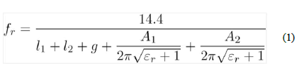
The ground plane (Grd l=10 mm) and radiator patch length (Sub w=14 mm) are denoted by l1 and l2, respectively; the ground plane and radiation patch areas are denoted by A1 and A2, respectively; and the gap between the radiation patch and the ground plane is denoted by g (thickness of substrate 0.25 mm).
The radiating patches of the proposed UWB MIMO antenna system are in the shape of an F, with a central rectangle measuring 7 mm in length and 5 mm in width. Two radiators were carved on opposite sides of the substrate. A step-shaped microstrip with a feedline size of feed l and a feedline size of feed w1 feeds the radiators. A step feed w2 (0.8 mm 1 mm) was added to the feed line to improve impedance matching. Modified ground planes (Grd l x Grd w) were also carved on opposite sides of the antenna substrate. To improve matching and extend the operating bandwidth of the planned antenna, small notches of size Grd cut w x Grd cut l are etched on both ground planes.
The current antenna design is the result of the evolution of much geometry, as shown in Figure 3. On one side of Antenna I in Figure 3, a step feed line feeds a rectangular radiating element, while on the other side; the modified plane of ground in Figure 5 (Ground iii) has been cut. As seen in Figure 5, the expected UWB bandwidth could not be achieved with this architecture. As a result, the radiator was resized, as seen in Figure 3. (Antenna numbers two). Due to the reduction in size, the matching in the lower UWB range has improved, but the matching in the upper frequency range of UWB has remained unsatisfactory. To improve matching in the upper UWB band, a tiny notch is created on the right Centre piece of the Antenna ii arrangement in Figure 3, which is shown in Figure 3 as Antenna iii. As can be seen in Figure 4, parametric research was also undertaken on the length of this notch (Cut l), which demonstrated that it had no significant effect on S11. Based on these findings, Antenna iii is selected as the required radiator for the proposed UWB MIMO antenna.

Figure 3: Different radiator shapes from which the proposed antenna was evolved.

Figure 4: S11 (Simulated), for various radiator configurations.
Ground plane effect on antenna performance
The ground plane plays a crucial role in impedance matching in the proposed UWB MIMO antenna architecture. Figure 5 depicts the proposed antenna's ground plane evolution. As illustrated in Figure 5, Ground I represent a complete ground plane with a length equal to the length of the substrate, i.e. 14 mm, whereas Ground ii indicates a drop in length (Ground l) from 14 mm to 10 mm. Ground iii additionally has small notches (Grd cut l Ground cut w) to increase coupling and response in the UWB band (Figure 5). Figure 6 shows S11 for various ground layouts. As can be observed in Figure 6, Ground I has a relatively narrow bandwidth and poor matching above 4 GHz. There is a resonance at 3 GHz, it appears. To help increase bandwidth, the length of the ground plane (Ground l) is reduced to 10 mm (Ground ii).

Figure 5: The suggested antenna is derived from a variety of different radiator shapes.

Figure 6: S11 (Simulated) for different radiators configuration.
This led in an additional resonance at roughly 7 GHz, in addition to the 3 GHz resonance (Figure 6). The band as a whole, however, agreed that the matching was poor. To make matching easier, rectangular notches of size Grd cut lx Grd cut w were cut out of the ground plane (Ground iii). This led in greater matching over the entire band of interest, as seen in Figure 6. A parametric analysis of notch width (Grd cut w) was also performed. The suggested antenna's bandwidth increased as the notch width was increased, as seen in Figure 6. Figure 6 only shows the S11 because the two radiating elements have the same geometry.
Results and Discussions
The prototype version of the UWB MIMO antenna under evaluation was built to verify the simulation results, and it is visualized in Section 6. To verify the software's claimed results, S-metrics, radiation patterns, gain, and performance-related MIMO parameters including Diversity Gain (DG) and Envelope Correlation Coefficient were measured (ECC). Antenna performance matrices are discussed in Section 3.1, whereas MIMO performance parameters are discussed in Section 3.2 (Figure 7).

Figure 7: The suggested UWB MIMO antenna prototype.
Antenna performance
Antenna performance parameters are included in this section. Figure 8 depicts the S-parameter results. Figure 8 shows that the observed and software-predicted outcomes are extremely similar. Figure 8 only displays S11 and S21 because the two radiators are identical and have similar ground planes (S11 is similar to S22). The antenna in question has a bandwidth of impedance of 10 GHz (2 GHz–12 GHz) and 10 dB isolation throughout the operating band, which is well acceptable for a conventional MIMO system.

Figure 8: (a) Simulated and (b) measured S-parameters.
Figures 9 and 10 depict 2D radiation plots (E and H-plane) for both elements of the proposed UWB MIMO antenna at 3 GHz, 7 GHz, and 12 GHz. At 3 GHz, 7 GHz, and 12 GHz, Figure 9 shows the simulated and observed radiation patterns of antenna elements 1 and 2 in the E plane, respectively. Whereas the simulated and measured radiation patterns of antenna elements 1 and 2 in the H plane at the above-mentioned frequencies are shown in Figure 10.

Figure 9: Simulated and measured radiation patterns E plane.

Figure 10: Simulated and measured radiation patterns in H plane.
Figures 9 and 10 demonstrate that the designed antenna system elements have a virtually omnidirectional radiation pattern across the entire frequency range. In Figure 11, the antenna's gain factor is shown. At frequencies of 3 GHz, 7 GHz, and 12 GHz, the measured gain factors are 1.8 dB, 2.8 dB, and 4.5 dB, respectively.

Figure 11: Measured gain of the proposed UWB MIMO antenna.
MIMO Performance Parameters
This section contains the parameters for the suggested UWB MIMO antenna's diversity performance in terms of Diversity Gain (DG) and Envelope Correlation Coefficient (ECC).
Envelope Correlation Coefficient (ECC)
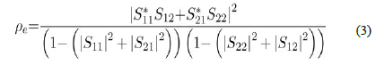
The Envelope Correlation Coefficient is the root of the correlation coefficient, and it describes the interaction between the MIMO system branches. ECC can be calculated using a 3D radiation pattern (pattern Equation (2) and S-parameters (Equation (3). In this study, an equation is utilized to determine simulated and measured ECCs (3). The ECC is shown in Figure 12.

Figure 12: Measured envelop correlation Coefficient.
The ECC in the chosen frequency band was found to be well below 0.5, indicating good diversity enactment.
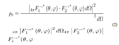
Under the excited port condition is the field radiation pattern of antenna system, and “·” is regarded as Hermitian product.
The measured significance value for ECC is 0.054 at 2.6 GHz, as shown in Figure 12.
Diversity Gain (DG)
The amount of improvement gained by using a multiple antenna system vs. a single antenna system is measured in diversity gain or apparent diversity gain (Gapp). Equation (4) was used to calculate the diversity increase in this study.
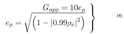
The measured DG value of the proposed antenna is shown in Figure 13. At the desired frequency band, Gapp is nearly 10 dB, ensuring good MIMO implementation.

Figure 13: Measured diversity gain. Coefficient.
Conclusion
A new cross-polarized 2 × 2 UWB-MIMO antenna system is designed in this paper. The antenna system was conceived and built as a prototype. Software was used to model and measure radiation patterns, peak gain, ECC, and gain diversity for the projected system. The two parts of this UWB-MIMO antenna system are cross polarized back-to-back and are made up of two 'F' shaped structures with a slotted fractured ground plane. With a total volume of 14140.25 mm3, the disclosed MIMO antenna system is incredibly tiny. The entire fractional bandwidth of the antenna system was measured at 141.5 percent. The ultrawideband response criteria are met with this number. Furthermore, the antenna system has a peak gain of 4.8 dB. There was a good match between measured and simulated results for prototype design.
References
- Alsaif H, Usman M, Chughtai MT, Nasir J (2018) Cross polarized 2 × 2 uwb-mimo antenna system for 5 g wireless applications. Prog Electromagn Res M 76:157-66.
- Kumar P, Dwari S, Kumar J (2017) Design of Biodegradable Quadruple-shaped DRA for WLAN/Wi-Max applications. J Microw Optoelectron Electromagn Appl 16:867-880.
- Zhiyong L, Qian Z, Huilong W, Xin L, Yunlin L (2010) A novel miniature UWB microstrip-fed antenna with L-shape ground. 2010 Int Symp Intell Signal Process Commun Syst 1-4.
- Thomas KG, Sreenivasan M (2010) A Simple Ultrawideband Planar Rectangular Printed Antenna with Band Dispensation. IEEE Trans Antennas Propag 1:27-34.
- Liu Y, Wang H, Li K, Gong S (2015) RCS Reduction of a Patch Array Antenna Based on Microstrip Resonators. IEEE Antennas Wirel Propag Lett 14:4-7.
- Sharma MM, Jangid M, Kaith P, Singhal S (2019) Fractal Antenna With Modified Partial Ground. IEEE Indian Conf Antennas Propag InCAP 1-3.
- Nasir J, Jamaluddin MH, Khalily M, Kamarudin MR, Ullah I (2016) Design of an MIMO Dielectric Resonator Antenna for 4G Applications. Wirel Pers Commun 88:525-36.

