 Spanish
  Chinese
  Russian
  German
  French
  Japanese
  Portuguese
  Hindi
Hindi Research Article, J Electr Eng Electron Technol Vol: 9 Issue: 5
Design and Simulation of Half Wave-dipole Antenna for LTE Applications Using CST microwave Studio
Mohammed Mynuddin1* and Md Ziaur Rahman21 Dept. Electrical and Computer Engineering, Georgia Southern University Statesboro, GA, USA
2 Dept. Civil Engineering,Dhaka International University, Dhaka,Bangladesh
*Corresponding Author : Mohammed Mynuddin
Dept. Electrical and Computer Engineering,
Georgia Southern University, Statesboro, GA, USA.
Tel: 9124813318
Email: mm40771@
georgiasouthern.edu
Received: July 27, 2020, Accepted: August 24, 2020, Published: September 10, 2020
Citation: Mohammed Mynuddin (2020) Design and simulation of half wave-dipole antenna for LTE applications using CST microwave studio, USA, J Electr Eng Electron Technol, 9:5
Keywords: Dipole Antenna, CST MWS
Introduction
The most common practical wire antenna is the dipole antenna. The dipole antennas may be categorized as Hertzian dipole, half-wave dipole, small dipole etc. The most balanced and commonly used type of antenna is the dipole antenna. It can be used alone as well as it is incorporated in many other antenna designs. For the wireless communication of high-speed data for mobile phones and data terminals, Long-Term Evolution (LTE) is considered as a standard and is commonly marketed as 4G LTE. According to the principle of the GSM/EDGE and UMTS/ HSPA network technologies a different radio interface together with core network improvements are developed to increase the capacity and speed. LTE is being gradually developed to ensure that future requirements and expectations are met and planned in the best possible way. LTE is critical to delivering lower cost per bit, high-performance connectivity and user experience required to tackle mobile broadband challenges such as device development, data-intensive services and the implementation of new machine-to-machine (M2 M) applications [1]. Analyses of the advantages and disadvantages of the alternatives of the small monopoly antenna design discussed on[2] such as meandered line antenna, inverted-L antenna, inverted-F antenna, planar inverted-F antenna, and multiband antenna consisting of different types of radiators for performing multifunctional operation of L TE-USB antennas. The molded interconnect device (MID) technology is used to design of a long-term evolution (LTE) antenna presented on [3] as well as its integration on the 3D surface of the mounting compartment of the automotive roof antenna. This antenna provided an input matching better than 10 dB in the desired frequency band and exhibited an unidirectional radiation characteristic in the horizontal plane. This antenna provides an input of more than 10 dB in the desired frequency band and has an unidirectional radiation characteristic in the horizontal plane. The design of a long-term evolution antenna is therefore investigated on [4]. It is designed to be mounted under a standard plastic cover on a car’s roof. The antenna operates at a wide frequency band (from 698 MHz to 960 MHz and from 1470 MHz to 2700 MHz) in small mounting volume and it requires no matching network. In [5], a simple half-wave dipole antenna has been designed and analyzed for wireless applications. The Resonant frequency for the dipole antenna was 5 GHz and as a simulation tool CST Microwave Studio (MWS) has been used. A simple half-wave dipole antenna for wireless applications has been developed and analyzed in [5]. In this project the resonant frequency for the dipole antenna was considered as 5 GHz and CST Microwave Studio (MWS) was used as a simulation tool. Various researches that also discussed different applications, such as [6]-[8], can be done using dipole and half wave dipole antenna. The general construction of a half-wave dipole antenna is shown in Fig.1.

Figure 1: Half-Wave Dipole Antenna
There is a gap between two halved wave dipole antenna arms for feeding purposes. Here, the length, thickness and feeding gap of the antenna is denoted by L, D and g. The radiation resistance of the halfwave dipole is 73 Ohm and it matched with the line impedance [9]. The main purpose of this paper is to design and simulate a half-wave dipole antenna by using CST simulator and to operate at 2.6GHz with high gain in LTE (4G) applications.
II. DESIGN PARAMETERS OF HALF-WAVE DIPOLE ANTENNA
The dimension of the antenna is changed according to the resonant frequency and the resonant frequency is taken as 5GHz. several dimensions of the antenna have been calculated by using this resonant frequency. Table-1 illustrates all the dimensions of the antenna. Resonant frequency, fr=2.6GHz and the velocity of light c=3×10⁸ ms-1.
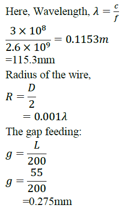
| Parameter | Value | Unit |
|---|---|---|
| Resonant Frequency (fr) | 2.6 | GHz |
| Wavelength | 115.3 | mm |
| Impedance | 7.3 | Ω |
| Length of the dipole (L) | 55 | mm |
| Radius of the dipole (R) | 0.1153 | mm |
| Gab feeding of the dipole (F) | 0.275 | mm |
Table 1: Design parameters of the antenna.
III. RESULT AND DISCUSSIONS
CST is used to model and simulate the half-wave dipole antenna. The 3D and multilayer structures of general shapes are analyzed by this software. For the design of different types of antennas, it has widely been used. It can be also be used to calculate and plot the return loss, standing wave ratio from Smith charts, Real power Vs Frequency, VSWR, E-field and H-field distribution, gain as well as radiation patterns.
A. Return Loss and Real Power: From Fig. 2 shows that the antenna is resonating at 2.57 GHz. Moreover, the value of return loss has been found as -32.751dB.

Figure 2: Return loss from CST
In Smith chart figure 3 shows the standing wave ratio s is 1.128.

Figure 3: Smith Chart
B. Voltage Standing Wave Ratio (VSWR): According to [10] VSWR should be between 1 and 2. In Figure 3 shows VSWR of dipole antenna less than 2. The good result of VSWR takes it from CST equal 1.128. In figure 4 describes the different real power for this pro-posed antenna. The power losses in the metals is 0.003618W and accepted power is 0.49...W.
C. E-field and H-field Distribution
High gain measured at 2.6GHz equal 1.951dB as shown in Fig. 4. Far-field radiation pattern has been shown in the Fig.8. Directivity has found as 2.026 dBi. Obtained directivity was almost identical to the theoretical ones [7]. Red color shows the maximum radiation.
| Parameter | Value(2.6GHz) | Value(2.4GHz) | Unit |
|---|---|---|---|
| Resonant Frequency (fr) | 2.57 | - | GHz |
| Directivity | 2.026 | - | dBi |
| Gain | 1.951 | - | dB |
| Return Loss | -32.751 | - | dB |
| Total Efficiency | 98.551% | - | - |
| VSWR | 1.128182 | - | - |
Table 2: Simulated results of the designed antenna.

Figure 4: Real Power Vs Frequency

Figure 5: Real Power Vs Frequency

Figure 6: VSWR from CST

Figure 7: E-field Distribution of the designed Antenna

Figure 8: H-field Distribution of the designed Antenna D. 3-D Far-Field Radiation Pattern for Directivity and Output Gain

Figure 9: 3-D Far-Field Radiation Pattern for Directivity for 2.4GHz

Figure 10: 3-D Far-Field Radiation Pattern for Directivity for 2.6 GHz

Figure 11: Polar Plot for Elevation Angle

Figure 12: Antenna gain for 2.4GH
Conclusion
A half-wave dipole antenna has been designed and simulated using CST software that facilitates the simulation. To obtain the target frequency of 2.6GHz for the LTE application a popular practical half-wave dipole antenna was selected. Return loss was acquired as -32.751 dB which shows the characteristic of reflection coefficient. The VSWR is less than two but the directivity and gain are higher than 2.4GHz of a dipole antenna.
References
- Gampala Gopinath (2011) Antenna Design Considerations for LTE Mobile Applications” IEEE Antennas & Propagation Society.
- Mohamed NI, Rahman TA, Leow CY (2012) Issues and challenges of LTE antenna designs for USB-dongle device. IEEE-APS Topical Conference on Antennas and Propagation in Wireless Communications (APWC).
- A Friedrich, B Geck, O Klemp, H Kellermann (2013) On the design of a 3D LTE antenna for automotive applications based on MID technology. European Microwave Conference (EuMC).
- Goncharova I, Lindenmeier S(2014) A high-efficient 3-D Neferantenna for LTE communication on a car. 8th European Conference on Antennas and Propagation (EuCAP).
- Singh Parminder, Sharma Ankita, Uniyal Neha, Kala Richa (20l2) Half-Wave Dipole Antenna for GSM Applications. Intemational Journal of Advanced Computer Research 2: 2277-7970.
- Liang MC, Huang KC, Lin ST, Lin SJ (2005) The bended C-patch dipole antenna St. IEEE Intemational Symposium Antennas and Propagation Society.
- Yu Wei, Hui Huang, Zhong, Zhi Qiang, Zhou Heng (2015) A short Dipole Antenna, 17th International Conference on High Power Particle Beams (BEAMS).
- Balanis, Constantine A (2005) Antenna Theory Analysis and Design”, John Wiley & Sons, 3:182.
- Wu Di,Wideband dipole antenna for 3G base stations (2005) IEEE International Symposium on Microwave, Antenna, Propagation and EMC Technologies for Wireless Communications Vol 1 IEEE.
- Ziaur Rahman Md, Mynuddin Mohammed (2016) Design and Simulation of High Performance Rectangular Microstrip Patch Antenna Using CST Microwave Studio GSJ 8: 2320-9186.

