 Spanish
  Chinese
  Russian
  German
  French
  Japanese
  Portuguese
  Hindi
Hindi Research Article, J Electr Eng Electron Technol Vol: 7 Issue: 2
Effect of Geometry Generator Variation Design 12 Slot 8 Pole on Power Efficiency Design
Windarto J*, Sudjadi, Karnoto, Sukmadi T, Santoso I and Desmiarti A
School of Electrical Engineering, Diponegoro University, Semarang Indonesia
*Corresponding Author : Windarto J
School of Electrical Engineering, Diponegoro University, Semarang Indonesia
Tel: +(62) 82131048558
E-mail: jokowind@yahoo.com
Received: May 25, 2018 Accepted: June 12, 2018 Published: June 19, 2018
Citation: Windarto J, Sudjadi, Karnoto, Sukmadi T, Santoso I, et al. (2018) Effect of Geometry Generator Variation Design 12 Slot 8 Pole on Power Efficiency Design. J Electr Eng Electron Technol 7:2. doi: 10.4172/2325-9833.1000161
Abstract
The development of generator technology continues to improve from year to year. The scope of such improvement varies from the shape, design, size, the usage of material, and even regarding to the efficiency of the generator output power. However, the role of the software to design such electric machinery in the improvement of generator technology development should not be ignored. So before designing and manufacturing the electric machines, especially generators, it is important to know the specifications of materials which are needed in the design of the generator, regarding the initialization of each constituent part of the generator for example, in the pre-design process of a 12 slot 8 pole generator is a must.
Keywords: Output power; Input power; Efficiency
Introduction
The development of generator technology continues to improve from year to year. The scope of such improvement varies from the shape, design, size, the usage of material, and even regarding to the efficiency of the generator output power. However, the role of the software to design such electric machinery in the improvement of generator technology development should not be ignored. So before designing and manufacturing the electric machines, especially generators, it is important to know the specifications of materials which are needed in the design of the generator, regarding the initialization of each constituent part of the generator. Therefore, it is expected that further research could be able to provide such information regarding the materials needed to build the generator. Many prior researches and studies used Trial and Error methods, especially here in Indonesia. The method in other words means to directly work on the building process of the generator that has been designed mathematically. This is based on the assertions made for example, the geometric design which is used. Then came the idea of designing a generator with the help of software, such as, Magnet to create the simulation of the generator. While manufacturing or designing a generator, one must determine the ideal efficiency value of the generator so as to be able to reach the desired target value. In designing a generator using electromagnetic software, such as Infolytica, there are many aspects that need to be considered, either before or during the design process. It's because many parameters use equations which needs to be calculated when designing the generator [1-5]. The width of the air gap is one of the parameters that uses equation because the air gap will later affect the output and performance of the generator.
Modeling and Simulation
Pre design 12 slot 8 pole generator
The design drawing is the stage to draw the geometric shapes of the stator, rotor, slot, air gap width, and determining the appropriate magnet layout so that it will produce a good sinusoidal signal. Design drawings can be done directly using software such as Magnet Infolityca, as well as CAD software, Solid work, Inventor and AutoCAD. Figures 1 and 2 shows a generator design made using Infolityca software.

Figure 1: Design ¼ model generator.

Figure 2: Design 3D ¼ model generator.
Generator testing variation: As for the initialization of material for each part, the value of the diameter of each part is very influential to the generated output value (Table 1). We used three variations of value (mm) in the rotor, stator, teeth, and magnet.
| Part | Material |
|---|---|
| Airbox Stator Coil Teeth Magnet Rotor Airgap Rotor Airgap Stator |
AIR Carpenter: Silicon steel Copper: 5.77e7 Siemens/meter Carpenter: Silicon steel PM12: Br 1.2 mur 1.0 Carpenter: Silicon steel AIR AIR |
Table 1: Initialization on each part.
1. Variations of Stator Geometry (Table 2)
| Part | Size (mm) | ||
|---|---|---|---|
| Variation 1 | Variation 2 | Variation 3 | |
| Air box Stator Coil Teeth Magnet Rotor Air gap Rotor Air gap Stator |
90 65 67 10 49 46 49.5 50 |
90 75 67 10 49 46 49.5 50 |
90 85 67 10 49 46 49.5 50 |
Table 2: Size of each variation in the stator section.
2. Variations of Teeth Geometry (Table 3)
| Part | Size (mm) | ||
|---|---|---|---|
| Variation 1 | Variation 2 | Variation 3 | |
| Air box Stator Coil Teeth Magnet Rotor Air gap Rotor Air gap Stator |
90 75 67 7 49 46 49.5 50 |
90 75 67 10 49 46 49.5 50 |
90 75 67 13 49 46 49.5 50 |
Table 3: The size of each of the foreign variations in the teeth section.
3. Magnetic Geometry Variations (Table 4)
| Part | Size (mm) | ||
|---|---|---|---|
| Variation 1 | Variation 2 | Variation 3 | |
| Air box Stator Coil Teeth Magnet Rotor Air gap Rotor Air gap Stator |
90 74 66 10 48 46 48.5 49 |
90 75 67 10 49 46 49.5 50 |
90 76 68 10 50 46 50.5 51 |
Table 4: Size of each variation on the magnet.
4. Variations of Rotor Geometry (Table 5)
| Part | Size (mm) | ||
|---|---|---|---|
| Variation 1 | Variation 2 | Variation 3 | |
| Air box Stator Coil Teeth Magnet Rotor Air gap Rotor Air gap Stator |
90 65 67 10 49 46 49.5 50 |
90 75 67 10 49 46 49.5 50 |
90 85 67 10 49 46 49.5 50 |
Table 5: Size of each variation in the rotor section.
Model simulation
Simulation is used to determine the angle value of the rotor movement, two methods of calculation are performed respectively. First, by determining the mechanical angle value (degree/ms) as in the mechanical equation, then continued by determining the electrical angle value (degree/ms), shown as follows
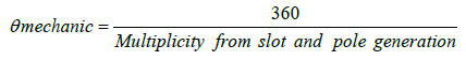
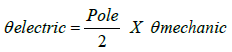
From the above equation, it can be seen that when the magnitude of the mechanical movement for 12 Slot 8 Pole Generator is 15 degrees/ ms, the electric movement is equal to 60 degrees/ms on 360 degree model. In the stop motion parameter, the stop time value of 0.015 s are being used because the design process of 12 slot 8 pole generator uses ¼ model. To determine the value of the sampling movement, however, it can be calculated using the following equation.
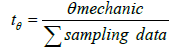
From the above equation using samples in total of 100 data, we obtained the step value of 0.00015 degrees/s. Before doing the simulation by rotating the rotor, there are some steps that need to be done so that the rotor can rotate automatically. First of all, we need to enter the value of the rotor movement which starts from 0 s and ends at 0.015 s where the movement of the rotor occurs along 90 degrees, as shown in Figure 3

Figure 3: Insertion of speed based motion values.
Next, we need to enter the transient value with the initial value 0 s, and ends at 0.015 s where every 0.00015 s of rotor movement is being sampled until the movement to 90 degrees so that 100 data could be obtained, the process of transients are shown in Figure 4 .

Figure 4: Transient options value entry.
Meanwhile, regarding the solve options parameters that needs to be set is the value of the Polynomial order to be used. Figure 5 shows the solve options setting screen.

Figure 5: Polynomial order settings.
The next process is the manufacture of rectifier circuit as shown in Figure 6. It is the step to make the circuit which is located in the generator coil, because every generator test using the Infolytica Magnet Software uses different circuits, both for a loaded generator and a generator without load. Figure 6 shows a circuit which got 100 ohm load, using 50 loops where the junction voltage value for each generator is 0.7 V as shown by the Infolytica Magnet Software.

Figure 6: Rectifier circuit.
Result and Analysis
Results of simulation and data processing
The generator works by changing the inputs of rotational speed (radians per second) and torque (Newton meter), producing outputs of voltage (Volt) and current (Ampere). The generator rotates with input through a shaft derived from the turbine. Input from the turbine in the form of turbine rotational speed, as well as the torque provided can be referred as mechanical power.
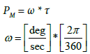
Where
PM : Mechanical Power (Watt)
ω : Angular Velocity (rad /s)
τ : Torque (Newton meter)
The Output Generator is the Current and Voltage of the resulting Flux and the installed load, which is referred to as electric power.
PE = V * I
Where
PE : Electric Power (Watt)
V : Voltage (V)
I : Current (Ampere)
The input power for the generator is mechanical power and its output power is electric power, therefore to perform efficiency calculation can use the following equation.
Analysis from the result
Power output generator: The calculation of the output power of the data in the simulation is shown in Table 6. From Table 6 we get a comparison graph of output power in each variation of geometry as in Figure 7.

Figure 7: Comparison Graph of the output power of each part of the geometry variation.
| Stator | Teeth | Magnet | Rotor | |
|---|---|---|---|---|
| Variation 1 | 1.9040 | 1.2931 | 2.2962 | 1.4203 |
| Variation 2 | 1.9489 | 1.9489 | 1.9489 | 1.9489 |
| Variation 3 | 1.9496 | 2.1701 | 1.3926 | 2.5809 |
Table 6: Comparison results of output power of each part.
Power input generator: The calculation of the input power of the data in the simulation is shown in Table 7. From Table 7 we get a comparison graph of input power in each variation of geometry as in Figure 8.

Figure 8: Comparison Graph of the input power of each part of the geometry variation.
| Stator | Teeth | Magnet | Rotor | |
|---|---|---|---|---|
| Variation 1 | 3.0525 | 3.2660 | 4.3696 | 1.4203 |
| Variation 2 | 2.0478 | 2.0478 | 2.0478 | 1.9489 |
| Variation 3 | 4.0951 | 4.4045 | 2.9442 | 2.5809 |
Table 7: Comparison results of input power of each part.
Generator efficiency: The calculation of the efficiency of the simulated data in the simulation is shown in Table 8. From Table 8 we can see the comparison of efficiency values for each geometry variation as shown in Figure 9.

Figure 9: Comparison graph of efficiency values of each part of geometric variation.
| Stator | Teeth | Magnet | Rotor | |
|---|---|---|---|---|
| Variation 1 | 62.3761 | 39.5935 | 52.5512 | 49.176 |
| Variation 2 | 95.1723 | 95.1723 | 95.1723 | 95.172 |
| Variation 3 | 47.6089 | 49.27 | 47.3006 | 48.631 |
Table 8: Comparison results of efficiency value of each section.
Conclusions
From the experiment in the software infolityca, it can be concluded as follows:
1. In the pre design process generator 12 slot 8 pole, each constituent part of the generator must be initialized.
2. The diameter value in the generator greatly affects the resulting output value.
3. In the first variation the highest efficiency value is in the stator which is 62.3761%
4. In the second variation an efficiency value is 95.1723%
5. In the third variation the highest efficiency value is in the teeth section which is 49.27%.
References
- Kenjo T, Nagamori S (1985) Permanent-Magnet and Brushless DC Motor. Oxford University Press.
- Hendershot JR, Miller TJ (1994) Design of Brushless Permanent Magnet Motors. Motor Design Books LLC.
- Fitzgerald AE, Kingsley C, Umans SD, James B (2003) Electric Machinery. McGraw-Hill
- Chapman S (2005) Electric Machinery Fundamentals. Tata McGraw-Hill Education
- Chapman SJ (2002) Electric Machinery and Power System Fundamentals. McGraw-Hill.

