Case Report, J Spine Neurosurg Vol: 7 Issue: 3
How I Fix Spinopelvic Abnormalities With Hyperlordotic Cages
Joseph Yazdi* and Thomas Lee
SpineMore Surgical Associates, Saint Louis, USA
*Corresponding Author : Dr. Joseph Yazdi, MD, FAANS
SpineMore Surgical Associates, Inc., 12152 Tesson Ferry Rd., Saint Louis, MO 63128, USA
Tel: (314) 973-2955
Fax: (314) 842-6972
E-mail: joeyaz21@yahoo.com
Received: June 05, 2018 Accepted: June 19, 2018 Published: June 26, 2018
Citation: Yazdi J, Lee T (2018) How I Fix Spinopelvic Abnormalities with Hyperlordotic Cages. J Spine Neurosurg 7:3. doi: 10.4172/2325-9701.1000300
Abstract
In recent years, normalization of spinopelvic parameters has become a significant focus in the treatment of adult spinal deformity (ASD). Numerous studies have shown that by correcting those parameters, the patient-reported outcomes have statistically improved significantly. However, very little is published about the actual technique used to accomplish this task. In this article, we present the case of a patient with significant spinopelvic parameter abnormalities. We will discuss step-by-step how the case was analyzed preoperatively and the steps taken during surgery to achieve our goals. We will also discuss some pitfalls and how to avoid them. Short-term post-operative films are used to demonstrate the effectiveness of our technique and decision making process.
Keywords: Spinopelvic parameters; Lumbar lordosis; Hyperlordotic cages; Pelvic incidence; Pelvic tilt
Case Presentation
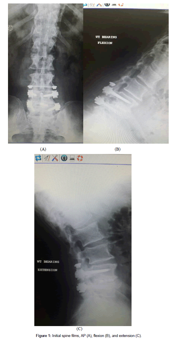
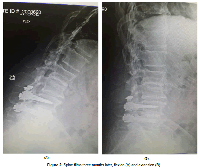
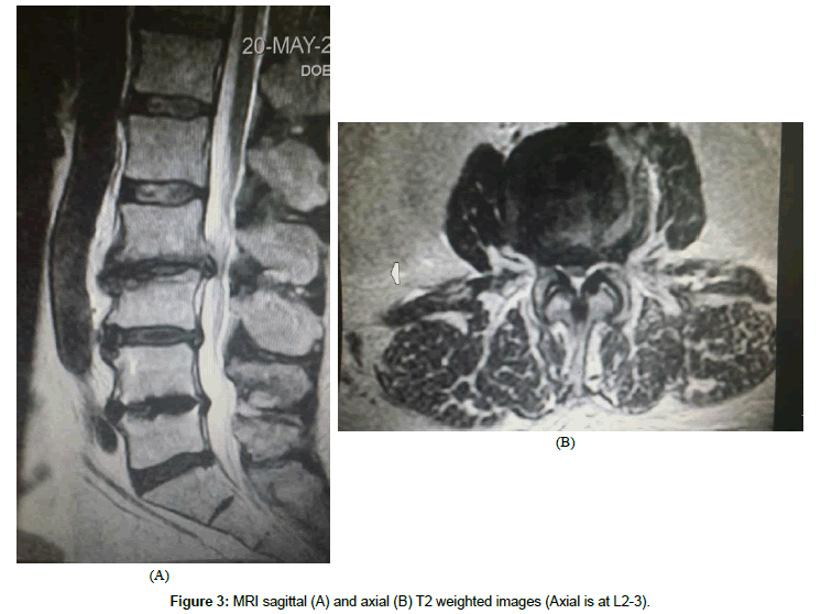
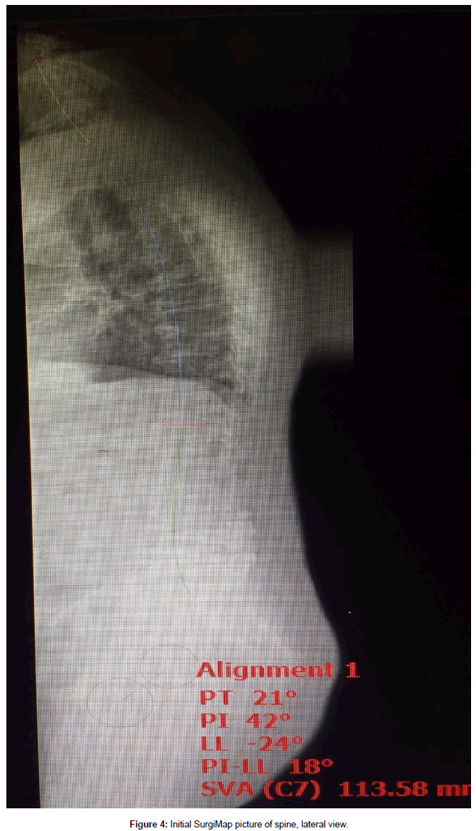
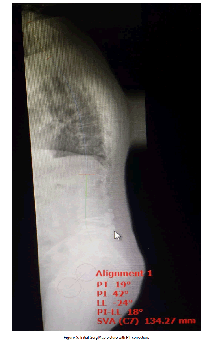
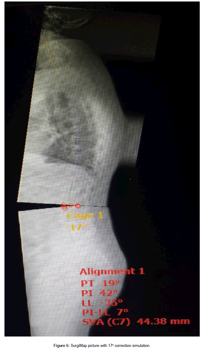
This 61 year old male presented with complaint of constant severe lower back pain (LBP) after a fall which occurred two months prior to presentation. His pain continued to worsen despite rest and medication. It was radiating to the left sacroiliac joint area as well as the left lateral thigh with a severity of 7-9/10 on the visual analog scale (VAS). His past medical history was significant for rheumatoid arthritis (RA), NIDDM, peripheral neuropathy, and L4-5 transforaminal lumbar interbody fusion (TLIF) with pedicle screw instrumentation. The TLIF was performed four years prior for treatment of recurrent disc herniation. Plain films on presentation showed fusion and instrumentation at L4-5 and no motion abnormalities on flexion or extension views (Figures 1A-1C). His examination was significant for decreased range of motion of the lumbar spine, severe tenderness to palpation of the left sacroiliac joint, positive pain response to left hip flexion and external rotation, as well as numbness of his left foot which was attributed to diabetic peripheral neuropathy. He was diagnosed with lumbar strain, left sacroiliitis, and left lumbar radiculopathy. He underwent physical therapy, left sacroiliac joint injection, and L5-S1 epidural injections. These treatments provided some temporary relief from pain. Three months later, he developed acute onset of left leg weakness and numbness which was confirmed by our examination. Significant findings included weakness of left iliopsoas at 2/5, knee extension at 3/5, and gastrocnemius at 4/5. There was also acute onset of sensory loss involving the left anterior thigh. Plain films of the lumbar spine on that visit showed significant deterioration at the L2-3 disc space as well as L3 endplate erosion (Figures 2A and 2B). An MRI was obtained which confirmed the above findings, no evidence of infection, and severe stenosis at L2-3 (Figures 3A and 3B). Full spine films were obtained and evaluated using SurgiMap (Nemaris Inc., NY, USA) (Figure 4). Pelvic tilt (PT) was 210 which is slightly elevated. Pelvic incidence (PI) was within normal range at 420. However, lumbar lordosis (LL) was only 240. PI-LL was 180, whereas normal values are equal or less than 90. Furthermore, C7 sagittal vertical alignment (SVA) was 113.58 mm, and normal values are up to 50 mm only. After correcting the PT to 190, then C7 SVA increased to 134.27 mm (Figure 5). In order to correct such a large abnormality, we simulated our surgical planning with various hyperlordotic cages. The best correction was achieved using a hyperlordotic cage with a goal of 17 degrees of correction. This would predict a resultant LL=350, PI-LL=70, and C7 SV=44.38 mm (Figure 6).
There are a number of variables that need to be considered in order to choose the correct implant. These include the desired degrees of the correction, the surface area available for fusion within the cage, and the best surgical approach for placement of such a cage. The degree of correction not only depends on the lordosis of the cage but also on whether the ALL (anterior longitudinal ligament) and the facets will be resected as well. We will outline how we approach all these variables in the discussion section. Suffice it to say for now that given our calculations, the best implant was a 200 hyperlordotic cage placed through a lateral interbody approach, and the surgery also required resection of the ALL and the facets in order to achieve the desired results. Furthermore, given the biomechanical load of this type of construct, we prefer the addition of posterior fusion and pedicle screw fixation for greater stability and higher chance of fusion.
Surgical Technique
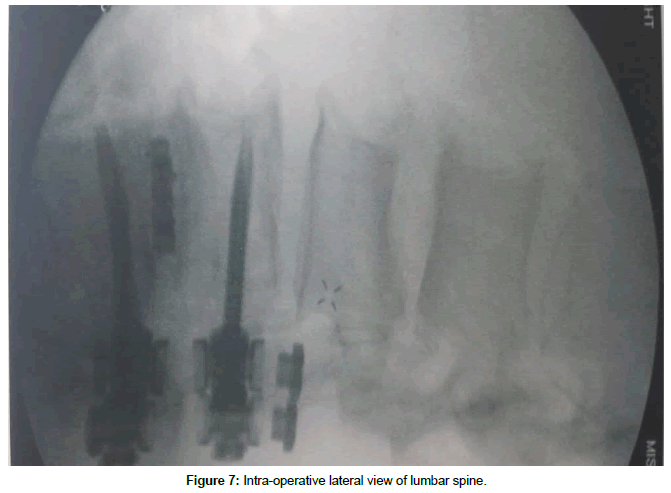
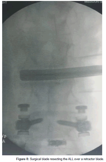
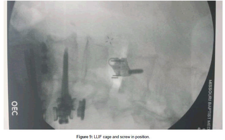
The patient was placed in a right lateral decubitus position and secured. A small roll was placed under the right iliac fossa up to the iliac crest in order to increase the angle between the ribs and left iliac crest. Care was taken to bend the ipsilateral hip in order to relax the psoas muscle. Fluoroscopy was used to make sure he was properly positioned and also to mark our left lateral incision (Figure 7). As can be seen, the 11th rib overlies the L2-3 disc space. Thus the working space would be between the 11th and 12th ribs. The incision was made between the 11th and 12th ribs. The 12th rib was mobilized by first working along its superior border and then deep to it. We bluntly reflected the parietal pleura and the diaphragmatic attachment from the undersurface of the 12th rib. Careful attention was given to the neurovascular bundle at the inferior aspect of the rib as it is mobilized inferiorly. The rest of the approach was performed as described by Ozgur et al. [1]. Briefly, the retroperitoneal space was entered bluntly. Serial dilation and stimulation was done over the L2-3 disc space with fluoroscopic guidance. The retractor was placed and the surgical field was stimulated again. An ipsilateral annulotomy was followed by a contralateral annulotomy, discectomy, and preparation of the endplates. Careful blunt dissection continued anteriorly over the annulus until we were able to place a narrow retractor blade anterior to the annulus. Great care was taken to go around the large anterolateral osteophyte and not damage the retroperitoneal vessels. After further dissection, a wider retractor blade was placed between the annulus and the narrow retractor. Discectomy proceeded anteriorly until there was only a thin remnant of the annulus remaining behind the ALL, which was then resected sharply over the retractor blade (Figure 8). Very careful attention was paid to the contralateral anterolateral aspect of the annulus as this is the most difficult part to reach and cut. After endplate preparation, various trials were used and finally a 200 22 x 55 x 17 mm cage was chosen. It was filled with demineralized bone matrix and placed into the disc space. This was secured using a 55 mm screw into L2 vertebral body through the plate screw hole (Figure 9). You can clearly see that the anterior aspect of the cage achieved good contact with the endplates above and below, but the posterior aspect did not. Incision was closed in the usual manner.
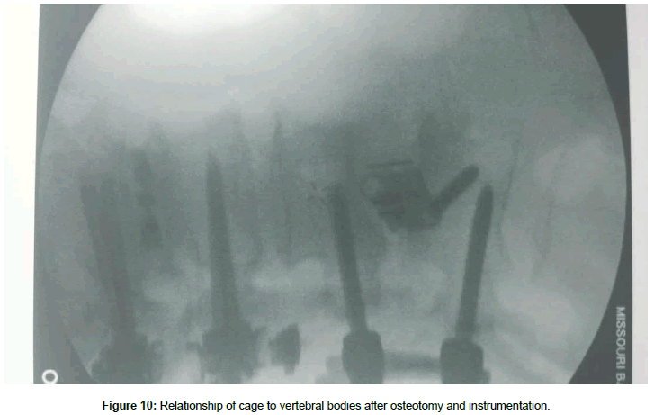
The patient was then turned prone onto a Jackson table and a midline incision was made. The posterior elements including the facets and the base of the transverse processes were exposed in the usual manner. Pedicle screws were placed using the open technique under neurophysiological and fluoroscopic control. Laminectomy and thorough decompression was achieved while preserving the L1-2 interspinous ligament. The osteotomy was completed by resecting the L2-3 facets. The rods were placed and some compression was applied. The set screws were secured. The desired lordosis was attained and there was proper contact between the endplates and the cage (Figure 10). Lateral fusion was performed and closure was done in the usual manner.
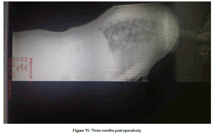
The patient was discharged home in two days. He immediately felt significant improvement in his posture. The pain and weakness resolved quickly. He had gone back to work with restrictions at six weeks. He still had some residual numbness over the left thigh at the three month visit. At that time, we also obtained full spine films (Figure 11). His post-operative spinopelvic parameters (SPP) were PT=18, PI=42, LL=-52, PI-LL=-11, and C7 SVA=-73.06.
Discussion
With an increasingly aging population, the incidence of ASD has risen dramatically [2,3]. Furthermore, quality of life is a significant concern for the elderly. Therefore, it is essential for the spine surgeon to correct the patient’s ASD in such a manner that would result in the best patient-reported outcome possible. A number of studies have shown that the C7 SVA and PI-LL strongly correlate with clinical outcomes [4-6]. As such, it is critical for the surgical plan to correct these parameters.
Our patient presented with acute endplate erosion at L3, severe stenosis at L2-3, SPP abnormalities, and acute onset of neurological deficits. The main cause for the SPP abnormality is the L3 endplate erosion. It would be exceedingly rare for the fall to have caused the L3 endplate changes five months after the event. However, there is a well-known relationship between RA and endplate erosion [7-10]. Ibrahim et al. [7] found lumbar endplate erosion in 39.3% of their RA patients. Yamada also showed a significant correlation in endplate erosion and degenerative disc disease in patients with RA [8]. We encountered both these changes in an acute manner in our patient. These led to the kyphosis at L2-3 level, and ultimately, his PI-LL mismatch.
Although the stenosis led to his acute neurological deficits, merely correcting the stenosis without addressing the rest of the spinal problems would only lead to further deterioration of the spine and progressively worsening dysfunction [11,12]. His stenosis and SPP abnormalities are best treated with decompression and fusion with instrumentation. In our practice, we use SurgiMap to fully define the extent of the spinal deformity as well as the surgical planning. The patient gets a full standing spine X-Ray in the AP and lateral views. The data are loaded onto the computer and the software enables us to measure the various spinopelvic parameters. In our case, PI was elevated due to pelvic retroversion. In order to get the true measure of SPP abnormalities, the PI has to be corrected to 190. This then gives you a true measure of the C7 SVA which was 134.27 mm. Correcting for the PI is a very important initial step. Without it, the degree of correction would be underestimated, which could lead to less than desirable results.
The second step is to choose the correct implant size. Based on the SurgiMap data, the best option was provided with 17 degrees of correction. In order to obtain this correction, one would need to consider the amount of correction that can be achieved by a cage, whether ALL or the facets need to be resected, and how subsidence would affect this construct in the long term. Although limited in the number of patients in their study, Marchi et al. showed that without ALL or facet resection, typical lordosis achieved through a lateral interbody fusion was about 50% of that provided by the cage. Furthermore, a wedge osteotomy added an additional 100 of lordosis to the construct [13]. Dr. Eastlack and his group also came to the same conclusions when evaluating their own data (Personal communication, La Jolla, CA). These factors are important for short term correction of lordosis. However, one must also account for some degree of subsidence in the long term as well. Although there are a number of studies that demonstrate the presence of graft subsidence, very few actually measure the degree of such subsidence [14-18]. Malham noted that in the 10% of patients that experienced subsidence, the average amount of subsidence was 3.2 mm. Their cage sizes ranged from 8-12 mm in height [18]. Our own (albeit unpublished) observation has been that the average amount of subsidence is about 10%-15% of the cage height. In our case, we planned for ALL and facet resection to give us 100 of lordosis. We would need to get an additional 10 degrees of correction from our cage. Since only half of this correction would be realized clinically, we chose a 200 implant. Adding 10%-15% subsidence would result in 17-18 degrees of correction.
Next step is to choose the footprint of the implant since this has implications in both the degree of subsidence as well as the rate of fusion. Marchi et al. compared the subsidence rate of 18 mm and 22 mm wide lateral interbody cages in relation to the percentage of the height of the cages [14].They grouped them into four categories. Those with 0%-24% subsidence were in group 0, 25%-49% subsidence in group 1, 50%-74% subsidence in group 2, and 75%-100% subsidence in group 3. In the 18 mm group, 48% were in group 0, 23% in group 1, 20% in group 2, and 10% in group 3. In the 22 mm group, 76% were in group 0, 13% in group 1, and 11% in group 2. Le reviewed their results comparing 18 mm and 22 mm implants and demonstrated a subsidence rate of 14.1% and 1.9% respectively [15]. When evaluating the biomechanics of interbody fusion, studies by Closkey et al. [19] as well as Kubosch et al. [20] confirm that best rate of fusion is achieved if the implant covers at least 24%-30% of the endplate surface area. Therefore, it is best to place as wide an implant as possible in order to achieve the least subsidence and best chance of fusion. In our case, the widest 200 implant was 22 mm if placed through a lateral approach.
Now that we have chosen our implant, we need to consider two surgical factors, specifically the approach and the proper technique to preserve the endplates. Typically, interbody fusions are done through an anterior (ALIF), lateral (XLIF/DLIF/LLIF), or posterior (PLIF/ TLIF) approach. The TLIF and PLIF approaches have significant limitation in implant size and shape, as well as the ability to distract the endplates. First, the most lordotic implants are generally less than 120. This limits the amount of correction that can be achieved. Second, the exposed neural elements are at a higher risk of injury as the cauda equine and the exiting nerve roots have to be contended with. Third, they have a high rate of subsidence [21]. The reason seems to be due to the implants being placed over the softest part of the vertebral endplates as well as the limited amount of endplate they actually cover [17,22,23]. Furthermore, the ALL cannot be resected safely from this approach. In a newer technique called cantilever TLIF (C-TLIF), the surgeon places a kidney shaped implant across the anterior apophyseal ring, performs bilateral posterior osteotomies, and then compresses using pedicle screws. Hioki et al. and Kida et al. analyzed the long term results of their patients undergoing C-TLIF and demonstrated that the amount of lordosis achieved was only about 3-6 degrees on average [24,25]. Furthermore, given that the discectomy has to be extended far anteriorly and all the way across the annulus for proper implant placement, there is increased risk of injury to the major retroperitoneal vessels. The ALIF approach solves many of the limitations of the posterior approaches. There is a large variety of implant sizes. The implants have large footprints which should increase the chance of fusion. The main drawback, however, is that the implant is usually placed over the central aspect of the endplate which correlates with its weakest part, and not over the apophyseal ring. The other concern is surgical exposure to the upper lumbar spine. Some approach surgeons are hesitant to expose the L2-3 disc level or above due to concerns of visceral injury. The LLIF procedure addresses all these issues, but it is limited to the disc spaces above L5-S1. During discectomy for LLIF, great care must be taken to not damage the endplate and especially the apophyseal ring; otherwise a great advantage of LLIF would be lost. Marchi et al. [13] showed that without endplate violation, they were able to achieve 58% of the lordosis provided by the cage. However, with endplate violation, they were only able to achieve 23% of the lordosis. Malham reviewed their series of 128 patients undergoing 178 lateral interbody fusion levels. They obtained CT scans on all patients on postoperative day 2 in order to evaluate for early cage subsidence as this would have been caused by their operative technique. They identified four patients in whom the caudal endplate was breached. In all these cases, the breach occurred during cage insertion [18]. Continued advances in instrumentation design and careful technique have helped with endplate preservation. It is very important to not use a disc shaver, and instead use blunt paddle spreaders when appropriate. Use fluoroscopy when penetrating the contralateral annulus with a Cobb elevator to make sure you are not damaging the contralateral aphophyseal ring. Use mostly ring curettes and reversed cutting box curettes for discectomy. We also recommend using the metal blades for insertion of the trials and implants as this is the most common step for endplate injury. On the other hand, advantages of LLIF are that an approach surgeon is not needed, recovery is much faster, length of stay in the hospital is shorter, and there is a lot less pain than an ALIF. We prefer LLIF in most cases and ALIF at L5-S1.
One advantage shared by both the ALIF and LLIF approaches is that the anterior longitudinal ligament (ALL) can be resected. With an LLIF approach, cutting the ALL requires great care due to the proximity of the great vessels. We typically work over the edge of the disc and slowly advance the retractor blades until we can place a small retractor blade anteriorly. After some more dissection anteriorly and thinning of the annulus from inside the disc space, we can then place a wider retractor blade. The ALL is cut sharply with a #11 blade (Figure 8). The manner of cutting is toward the disc space. ALL resection allows for great mobilization of the vertebral bodies so that the disc space can accommodate for a hyperlordotic cage. Given these advantages, we chose a lateral interbody approach for our case.
Another factor to consider when placing a hyperlordotic implant is the interface between the endplates and the cage. In our case, we used a 200 cage with 17 mm anterior height. One must be cognizant that the posterior height of this cage is only 8 mm. Therefore, a posterior osteotomy would be needed in order to approximate the surface of the endplate to the surface of the implant. Otherwise, in face of inadequate contact, the chance of fusion decreases significantly. Furthermore, from a biomechanical point of view, all the force between the endplate and the implant is through a narrow ridge anteriorly. This would increase the chance of subsidence, which could ultimately lead to SPP abnormalities. Taking all these factors into consideration, we were able to achieve focal lordosis of 170 at L2-3.
Another concern when placing a hyperlordotic implant is iatrogenic stenosis. In our patient, we planned on performing a decompressive laminectomy at L2-3 to treat the severe stenosis. After placement of the pedicle screws, the construct is placed under slight compression. While doing so, it is important to make sure the thecal sac or exiting nerve roots are not kinked by any residual ligament or bony edges. Neuromonitoring may aid in this aspect of the case as well.
Using our conservative approach, our goal was to simply correct the SPP. However, the initial results show a slight exaggeration in our correction as the PI-LL is -10 and C7 SVA is -73.06. It is very important to note that with this correction, the patient is asymptomatic and has remained so through the short term follow up. Furthermore, this degree of correction should allow the SPP to remain in the normal range even if there were some degree of subsidence. It has been our experience that over-correction in a short 1-2 level reconstruction is well tolerated. On the other hand, an all too common scenario involves spine surgeons who do not consider getting full spine X-Rays or correcting the SPP abnormalities. They would simply perform a fusion with an interbody cage that “fits” the space. Unfortunately, very commonly these patients complain of severe chronic LBP despite achieving complete fusion. The ensuing prolonged medical treatment only adds to the significant burden of medical costs associated with spine care in this country.
The weaknesses of our report are that it is a case report with only a three month follow up. However, we feel justified in that this paper is really concerned with elucidating the essential steps required pre-operatively and intra-operatively for SPP correction using hyperlordotic cages. Two year follow up of our series of patients will be needed to demonstrate the long term benefits of our decision process and technique. We certainly hope that it will be similar to those who have published from their extensive experience in correcting spinopelvic abnormalities [4-6].
Conclusion
Recognizing and correcting spinopelvic parameters is rapidly gaining prominence and may someday soon become the standard of care. However, there is a paucity of literature on the specific steps taken before and during surgery to achieve such correction. We detail the steps we take before and during surgery to achieve such results.
References
- Ozgur BM, Aryan HE, Pimenta L, Taylor WR (2006) Extreme Lateral Interbody Fusion (XLIF): A novel surgical technique for anterior lumbar interbody fusion. Spine J 6: 435-443.
- Robin GC, Span Y, Steinberg R, Makin M, Menczel J (1982) Scoliosis in the elderly: a follow-up study. Spine 7: 355-359.
- Schwab F, Dubey A, Pagala M, Gamez L, Farcy JP (2003) Adult scoliosis: a health assessment analysis by SF-36. Spine 28: 602-606.
- Schwab F, Lafage V, Patel A, Farcy JP (2009) Sagittal plane considerations and the pelvis in the adult patient. Spine 34: 1828-1833.
- Schwab F, Patel A, Ungar B, Farcy JP, Lafag V (2010) Adult spinal deformity-postoperative standing imbalance: how much can you tolerate? An overview of key parameters in assessing alignment and planning corrective surgery. Spine 35: 2224-2231.
- Bourghli A, Aunoble S, Reebye O, Le Huec JC (2011) Correlation of clinical outcome and spinopelvic sagittal alignment after surgical treatment of low-grade Isthmic spondylolisthesis. Eur Spine J 20: 663-668.
- Ibrahim M, Suzuki A, Yamada K, Takahashi S, Yasuda H, et al. (2015) The relationship between cervical and lumbar spine lesions in rheumatoid arthritis with focus on endplate erosion. J Spinal Disord Tech 28: E154-E160.
- Yamada K, Suzuki A, Takahashi S, Yasuda H, Tada M, et al. (2015) MRI evaluation of lumbar endplate and facet erosion in rheumatoid arthritis. J Spinal Disord Tech 27: E128-E135.
- Kawaguchi Y, Matsuno H, Kanamori M, Ishihara H, Ohmori K, et al. (2003) Radiologic findings of the lumbar spine in patients with rheumatoid arthritis, and a review of pathologic mechanisms. J Spinal Disord Tech 16: 38-43.
- Sakai T, Sairyo K, Hamada D, Higashino K, Katoh S, et al. (2007) Radiological features of lumbar spinal lesions in patents with rheumatoid arthritis with special reference to the changes around intervertebral discs. Spine J 8: 605-611.
- Hikata T, Watanabe K, Fujita N, Iwanami A, Hosogane N, et al. (2015) Impact of sagittal spinopelvic alignment on clinical outcomes after decompressive surgery for lumbar spinal canal stenosis without coronal imbalance. J Neurosurg Spine 23: 451-458.
- Fraser JF, Huang RC, Girardi FP, Cammisa FP Jr (2003) Pathogenesis, presentation, and treatment of lumbar spinal stenosis associated with coronal or sagittal spinal deformities. Neurosurg Focus 14: E6.
- Marchi L, Oliveira L, Amaral R, Castro C, Coutinho T, et al. (2012) Anterior Elongation as a Minimally Invasive Alternative for Sagittal Imbalance—A Case Series. HSSJ 8: 122-127.
- Marchi L, Abdala N, Oliviera L, Amaral R, Coutinho E, et al. (2013) Radiographic and clinical evaluation of cage subsidence after stand-alone lateral interbody fusion. J Neurosurg Spine 19: 110-118.
- Le TV, Baaj A, Dakwar E, Burkett C, Murray G, et al. (2012) Subsidence of polyetheretherketone intervertebral cages in minimally invasive lateral retroperitoneal transpsoas lumbar interbody fusion. Spine 37: 1268-1273.
- Behrbalk E, Uri O, Parks RM, Musson R, Soh RC, et al. (2013) Fusion and subsidence rate of stand alone anterior lumbar interbody fusion using PEEK cage with recombinant human bone morphogenetic protein-2. Eur Spine J 22: 2869-2875.
- Kim MC, Chung HT, Cho JL, Kim DJ, Chung NS (2013) Subsidence of polyetheretherketone cage after minimally invasive transforaminal lumbar interbody fusion. J Spinal Disord Tech 26: 87-92.
- Malham G, Parker R, Blecher C, Seex K (2015) Assessment and classification of subsidence after lateral interbody fusion using serial computed tomography. J Neurosurg Spine 23: 589-597.
- Closkey R, Parsons J, Lee C, Blacksin M, Zimmerman M (1993) Mechanics of interbody spinal fusion: Analysis of critical bone graft area. Spine 18: 1011-1015.
- Kubosch D, Milz S, Lohrmann C, Schwieger K, Konstantinidis L, et al. (2011) Risk of graft fracture after dorso-ventral thoraco-lumbar spondylodesis: Is there a correlation with graft size? Eur Spine J 20: 1644-1649.
- Hsieh PC, Koski TR, O’Shaughnessy BA, Sugrue P, Salehi S, et al. (2007) Anterior lumbar interbody fusion in comparison with transforaminal lumbar interbody fusion: implications for the restoration of foraminal height, local disc angle, lumbar lordosis, and sagittal balance. J Neurosurg Spine 7: 379-386.
- Matsumura A, Taneichi H, Suda K, Kajino T, Moridaira H, et al. (2006) Comparative study of radiographic disc height changes using two different interbody devices for transforaminal lumbar interbody fusion. Spine 31: E871-E876.
- Grant J, Oxland T, Dvorak M (2001) Mapping the structural properties of the lumbosacral vertebral endplates. Spine 26: 889-896.
- Hioki A, Miyamoto K, Hosoe H, Sugiyama S, Suzuki N, et al. (2011) Cantilever transforaminal lumbar interbody fusion for upper lumbar degenerative disease (minimum 2 years follow up). Yonsei Med J 52: 314-321.
- Kida K, Tadokoro N, Ikeuchi M, Kawazoe T, Tani T (2014) Can cantilever transforaminal lumbar interbody fusion (C-TLIF) maintain segmental lordosis for degenerative spondylolisthesis on a long-term basis? Arch Orthop Trauma Surg 134: 311-315.
 Spanish
  Chinese
  Russian
  German
  French
  Japanese
  Portuguese
  Hindi
Hindi 