Spanish
  Chinese
  Russian
  German
  French
  Japanese
  Portuguese
  Hindi
Hindi Research Article, Res Rep Metals Vol: 2 Issue: 1
Mechanical Impact on Metal: from the Destruction of Crystal to the Transmutation of the Nucleus
Marakhtanov MK1* and Marakhtanov AM2
Department of Materials Science and Engineering, University of Wisconsin- Milwaukee-53201 WI, USA
*Corresponding Author : Marakhtanov MK
Bauman Moscow State Technical University, 2nd Baumanskaya, 5.Moscow 105005, Russia
E-mail: mkm@bmstu.rua
Received: December 18, 2017 Accepted: January 26, 2018 Published: February 02, 2018
Citation: Marakhtanov MK, Marakhtanov AM (2018) Mechanical Impact on Metal:from the Destruction of Crystal to the Transmutation of the Nucleus. Res Rep Metals 2:1.
Abstract
We use metals for thousands years and still discover new properties they possess. Here it is experimentally shown that one the unknown properties of metal is its inertial explosion induced by mechanical impact. Unexpected characteristics of this explosion and parameters of its products are presented in comparison to the previously described electrical explosion of thin metal films and wires.
Keywords: Metal impact; Inertial explosion; Quasi free electrons; Electron impulse; Energy imbalance of oppositely charged particles; Disintegration metal crystal; Nuclear transmutation
Introduction
Solid metal can become a very fragile structure. The electronic impulse created in it artificially, is capable to destroy both a metal crystal [1] and, possibly, an atomic nucleus [2]. The cause of this impulse can be either the external electric field or the inertia of electrons in a mechanical impact [3]. The basis of these transformations lies in imbalance of the energy of interaction between the negative charges of quasi-free electrons and the positive charges of the nuclei (ions, atoms) in the lattice sites [4]. To destroy the metal, the energy of the imbalance εd must be transferred only to the electronic component of the metal, without affecting the crystal ions [5]. It is experimentally shown that an electronic impulse created by an electric field induces a metal explosion of duration Δt ≤ 10–5 sec. The critical current density jc = 1.32*109... 8.04*109 A/m2 for Sn, W, Ti, Cu, Ni, and Al, respectively, is sufficient for the electrical explosion of these metals [6]. The energy of imbalance εd that destroys metal is 0.05% ... 1.51% of the metal cohesive energy ε of the named metals. The imbalance energy is the smaller, the greater the atomic mass of the metal. It is experimentally shown that an electronic impulse formed by the inertial field arises in the projectile upon contact velocity with the target v ≥ 140 m/sec and upon deceleration of projectile a ≈ – 106 m/sec2. The impulse duration is Δτ = 10–7 sec. The duration of the inertial explosion is Δt = 10–6…10–5 sec. The temperature of the vapor products of inertial lead explosive reaches 22000 K. The imbalance energy causing an inertial lead explosion is only 0.99 ... 2.78% of lead cohesive energy [8]. The energy released by the inertial explosion is less than the cohesive energy of the exploded metal. The effectiveness of the explosion depends on the speed and material of the projectile, as well as on the geometry of the latter [9]. Quasi free electrons not only heat the products of this explosion. We assume that they lead to nuclear transmutation of the projectile’s metal. It has been experimentally established that dusty products of an inertial explosion of the projectile containing a bismuth alloy emit single α-particles with energy of ~ 8 MeV [10]. Spectral analysis showed the presence of platinum and boron at the site of interaction of the projectile with the target. These elements were absent in the projectile and in the target before the inertial explosion. These effects confirm a possibility nuclear transmutation of bismuth due to the phenomenon of inertial explosion [2].
Minimum Energy Destroying Metal Crystal
Still in the fourth edition of his book, published in 1971, Charles Kittel, exhaustively explained why metal crystal retains its shape and what is the role of an imbalance of energy, leading to the explosion of the crystal:
“To bind atoms into solids by the electrostatic attraction between the valence electrons (quasi free electrons, — the auth.) and the ion cores (lattice sites, — the auth.) we can do four things, which are not all compatible:
The positive ion cores should be kept apart, in order to minimize the Coulomb repulsion of like charges.
The valence electrons should also be kept apart.
The valence electrons should be kept close to positive ions, to maximize the Coulomb attraction of unlike charges.
These three suggestions may lower the potential energy of system, but they must be carried out in such a way that the kinetic energy of the system is not much increased. By quantum theory any localization of electrons tends to increase the kinetic energy” [4].
However, in what way and how "not much" you need to increase the kinetic energy so the system ceased to be a crystal, it does not say. Here we will try to answer these both questions. Electric current is the most organized form of transmission of energy. Therefore, we believed that many years of international experience with electric conductors will help us to determine the minimum energy that destroys the metal crystal. This is natural, because exploding wires used in technique for over two centuries, although for military purposes [11]. At first they were electrical fuses in sapper mines. Later, when the explodingbridge wire detonators to initiate explosives for a nuclear weapon needs [12] appeared in the production, electric explosion of metal (wires and filaments) have been the subject of scientific interest.
Some frames of high-speed cinemicrographic of electrical explosion of aluminum film, taken by scientists from California in the 1960-ies, are shown in Figure 1. Speed filming of 1.2*106 frames/s, the exposure time for one frame is 8*10–7 s. From these frames we can judge the development of the explosion of aluminum film at the place and time. The film was deposited in vacuum on glass substrate; its thickness δ ≈ 15 nm, a width of H = 25.4 mm, length L = 50 mm. The film was exposed by impulse of electric current from the capacitor C = 1.4 microfarad and the initial voltage U0 = 2000 V. The positive electrode of the capacitor was connected to the right end of the foil and the negative to the left [14].

Figure 1: Frames of high-speed cinemicrographic of electrically exploded aluminum film with a length of L = 50,8 mm and a width of H = 25.4 mm; the initial voltage across the length L is equal to U0 = 2000: 1 — zone of destruction in the form of separate streams; 2 — the zone of continuous destruction of the film; " + " — positive electrode; j — the direction of the electric current; υD — the direction of drift velocity of electrons; the white color image on the black background of the rest of the film corresponds to the area deleted by the explosion of aluminum; the image is positive [13].
A thin metal film is a nice tool for the formation of two-dimensional electron flow in a conductor. Thin we suggest to call such a film in which the ratio of thickness δ to the length of the free path λe of the electron tends to unity, k = δ/λe → 1, (Table 1). In this film, tracks of the explosion look like the image of the streams on the map.
| Parameter | Film metal | |||||
|---|---|---|---|---|---|---|
| Al | Cu | Ni | Ti | Sn | W | |
| Film thickness d, nm | 9 ± 1,4 | 27,5 ± 3 | 13,5 ± 2 | 29 ± 6 | 45 ± 18 | 45 ± 18 |
| Length λe at 273 Ú, nm | 16.0 | 42.5 | 6.5 | 1.3 | 4.1 | 10.3 |
| Density r, kg/m3 | 2698 | 8960 | 8902 | 4540 | 7310 | 19300 |
| Atomic mass ÃÂ, a.m.u. | 27 | 63.5 | 58.7 | 47.9 | 118.7 | 183.8 |
| Voltage Uc, V | 125.6 | 33.7 | 105.8 | 138.0 | 71.3 | 59.9 |
| Current density jc, A/m2 | 8.04*109 | 7.29*109 | 7.41*109 | 3.78*109 | 1.32*109 | 1.43*109 |
| Critical power ÃÂc, W/m3 | 5.05*1013 | 1.23*1013 | 3.92*1013 | 2.60*1013 | 4.72*1012 | 4.27*1012 |
| Quasi-free electron density n, m–3 | 1.79*1029 | 8.45*1028 | 1.82*1029 | 1.13*1029 | 5.53*1028 | 2.52*1029 |
| Drift velocity uD, m/s | 0.281 | 0.538 | 0.255 | 0.209 | 0.149 | 0.035 |
| Ratio f =uD/ uN | 937 | 1793 | 850 | 697 | 497 | 117 |
| Cohesive energy e, eV/atom [4] | 3.34 | 3.50 | 4.435 | 4.0855 | 3.12 | 8.66 |
| Ratio b=(Õõ/Õε)100, % | 1.51 | 0.25 | 0.58 | 0.56 | 0.24 | 0.05 |
| Energy imbalance εd, eV/atom | 0.0506 | 0.0087 | 0.0259 | 0.0277 | 0.0098 | 0.0041 |
Table 1: The parameters of the cold thin metal films, destroyed an electr ical explosion [6,15].
It is experimentally shown that these tracks always have the same polarized structure, thus confirming that the cause of their appearance in the metal does not change from one experiment to another (Figure 2). At the beginning of current impulse first appears a narrow gap across the metal film, t ≈ 0 s. Then network streams 1 occurs on the boundary of the gap 2 and always on the negative electrode side, t = 2.4 μs and t = 4.8 μs. Transverse gap and network streams grow in the direction L until they reach the final sizes, t = 7.2 μs. After that the destruction ends, and the electric current j in the film stops, t ≤ 7.2 μs.

Figure 2: Diagram of electrical explosion of a thin metal film: 1 - film; 2 - tracks of explosion; 3 - cathode-contact on a thin film; 4 - voltmeter; 5 - anode-contact on a thin film; 6 - glass substrate with a thickness of 3.4 mm; L = 20 ± 3 mm - film length; H = 5 ± 0,5 mm - width film; c I - the direction of drift velocity of the electron flow in the film; I -c the direction of the electric current in the film.
We estimate the maximum electric current (or electron impulse) density in that aluminum film as jÑ = Imax/(H×δ) ≈ 1.6*1012 A/ü2. According to (Figure 1), the impulse duration (and period of the electrical explosion of metal) can be taken equal to Δτ ≈ 10–5s, since t ≤ 7.2 μs. The curve of the current impulse I(t), is given [13], has the form of a nearly symmetrical peak height Imax ≈ 600 A, and a width at the base of the peak, Δτ ≈ 4*10–6 s, if the initial voltage of the capacitor U0 = 2500 V.
A known thickness and area of the film measured within the boundaries of white color (Figure 1), were used to estimate the volume of aluminum and the number of atoms of this metal, gone with the explosion. It turned out that in this experiment the energy of the capacitor per one remote Al atoms about 10 times greater than the cohesive energy of aluminum, ε = 3,34 eV/atom [4] (Table 1). A similar proportion of energy is found in practically all articles on exploding wires [14]. Therefore, their authors were able to study rather a product of the explosion than the minimum energy causing the explosion.
In our experiments the supply of electricity to the samples was different [6]. We explored films of six metals (Al, Cu, Ni, Ti, Sn, W) deposited in vacuum on the glass (Table 1). The film thickness δ = 9...45 nm, width of H = 5 ± 0.5 mm, length L = 20 ± 3 mm, (Figure 2). During each new experiment, we gradually increased the voltage between the ends of the film from zero to the critical value Uc within 20...40 s up to the time of the explosion film. This voltage was Uc = 33,7...138,0 for Cu...Ti, respectively, and was much smaller than U0 = 2000 in the American experiments. The critical current density at which the explosion occurs is jc = Ic/(Hδ) = (1,32…8,04).109 ÃÂ/m2 (Table 1). The voltage Uc and current Ic was measured approximately for 0.2...0.4 s before the explosion. Glass substrate did not crack under the film. It was destroyed only in the case if the external free surface of the film applied varnish coating thickness of about 65 microns [15]. Such is the effect of conventional explosives.
Films’ metal retained the crystalline form, staying cool, until the moment of reaching the value Uc [6]. No damages of the films were not at a voltage below mentioned Uc [15]. Increasing the voltage and current from zero to the critical values Uc and jc, we were able to determine the minimum energy causing the explosion of metal. For this purpose, the area S and the volume Vf of the exploded part of the film were calculated by the contours of the fracture zone (Figure 3). The error in determining the average area S and the average width l of the exploded strip of metal should not exceed ± 0.15. Knowing the volume Vf and density ρ, we calculated the number N of metal atoms have been removed by the explosion of the destroyed zone. The products of the explosion condense on the screen like dust. Therefore, we supposed that the explosion turns the metal from a solid state directly to vapor.

Figure 3: Aluminum (a), tin (b), copper (c), and nickel (d) films after the explosion at magnification of 80 μm per large division (a and d), and 35 μm per large division (b and c); l — width and S — area of blasted strip of metal; l — width and S — area of blasted strip of metal; separate streams (tracks of explosion) all metals are oriented identically relative to the direction of quasi free electrons flow; the image is positive negative [15] .
The current inside the metal is transported by quasi free or valence electrons. They are involved in at least two movement types: chaotic at a speed of Fermi (υF ≈ 6*106 m/s) and the collective flow to the anode with a drift velocity
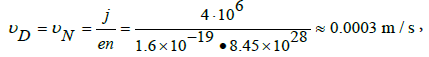 (1)
(1)
where it is assumed that j = jN = 4*106 A/m2 — normal current density in Cu or Al wires that are used in electrical engineering. In Table 1 shows ratio f = υD/υN, where the numerator is the value υD, calculated for samples with critical current density jc, and the denominator is the nominal drift velocity υN, = 0.0003 m/s. Using the ratio f we can assume that the kinetic energy of drift motion of free electrons increases in f2 = 1172...17932 = 1,37‧104...3,21‧106 times in the conductor with a critical density jc in comparison with the normal conductor with the current density jN . According to [4], this growth of kinetic energy of the system is characterized by a high degree of localization of electrons and the willingness of the crystal to the explosion [16]. The minimum electric power density under which the metal explodes is A c = ( j c V c ) l (Table 1). It corresponds to the minimum energy spent on electrical explosion of N atoms of a metallic film:
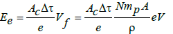 (2)
(2)
Where mp = 1.67.10–27 kg — mass of proton; A — atomic mass of metal, aum.; ρ — density of film metal, kg/m3 (Table 1); e is the elementary charge, used to replace Joules on eV. The duration of electrical explosion of a thin film is taken equal to Δτ = 10–5 s for all metals (Figure 1).
The total energy required for conventional evaporation of the same N atoms, is equal to Eε = εN, where ε — cohesive energy of the corresponding metal, eV/atom (Table 1). The ratio of the two energies is equal to
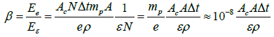 (3)
(3)
With its help we determine the minimum energy imbalance,
 (4)
(4)
that is enough to add to each free electron to break the metallic bond (cohesive) and blow up the metal. It is implied that the potential energy of lattice sites does not change and the valence of the investigated metals is equal to one. Indeed, the temperature of the film as a whole remained practically unchanged during the experiment, T ≤ 190 °C [6,17], and the kinetic energy of the electrons increased in f 2 ≈ 106 times by the end of the experience, see above. From (4) it follows, that the energy imbalance required for breaking the metallic bond and electrical explosion of metal, is equal to εd ≈ ε/β ≈ 0,004 (W)…0,051 (Al) eV/atom for the six investigated metals. It is about 0.05% (W)...1.51% (Al) from the cohesive energy (Table 1).
Our metallic conductors were in solid and cold state, although their current densities were f = 117 (W)…1793 (Cu) times more than in ordinary wire (Table 1). This was because the thin metal film is perfectly cooled by heat flow to the glass substrate. Thus, the electronic impulse, created by the electric field, destroys the metal in the process of electrical explosion; the duration of the explosion Δτ ≤ 10–5 s. In the known studies, the current density in the destructive impulse is called equal jc ≈ 1012 A/m2. This is excessive value, of course. In our experiments it is shown that the minimum or critical current density jc = 1.32*109...of 8.04*109 A/m2 for Sn...Al, respectively, is sufficient for the electrical explosion of metals (for six investigated metals). It is experimentally shown that the minimum energy imbalance needed for the electrical explosion of the metal is 0.05%...of 1.51% of cohesive energy W...Al, respectively (for six investigated metals). But to transfer this energy need only the electronic component of the metal without changing the temperature of the ions in the crystal lattice. Such non-equilibrium heating of electrons we can provide electric, inertial or thermal field [15], and electromagnetic radiation (laser) or electron beam. Energy imbalance εd the less, and the destruction of the metal the easier it is, the greater the atomic mass of the metal.
Electron Impulse and Inertial Explosion of Lead
Even a weak deceleration of a metallic sample causes an electron impulse in it, because the quasi free electrons continue to move by inertia. This effect was used to measure the mass of an electron in a fundamental experiment with a copper coil [17]. In that experiment the copper wire coil was rotated around the longitudinal axis. Then it was stopped abruptly by means of “the brake strap made from heavy leather belt” [16,17]. The coil’s negative acceleration was only a = – (40 ... 560) m/sec2, and the maximum wire speed before braking is υ = 63 m/s [15]. This proved enough to throw out free electrons from the stopping coil into the external measuring circuit. We made a similar experiment with a lead bullet and a lead projectile, shooting at a solid target. As it turned out, weak electronic impulse can be caused even by a shot from an air rifle [18]. A powerful electronic impulse, destroying both the projectile and the target, was obtained with the help of a powder booster. It was mentioned above, see Section 2, that the greater the atomic mass of a metal is, the more probable becomes its destruction, and the lower is the energy of imbalance εd. Therefore, we chose lead standard bullets "Barracuda Match" with a mass m = 0.667 grams for shots from the air rifle "GAMO-CFX" (Figure 4a). The diameter of the bullet is d = 4.50 mm, the length L = 8 mm. The muzzle velocity of the bullet is v = 220 ... 240 m/sec. A marble slab measuring 400 × 500 × 40 mm and weighing about 22 kg served as the target for the lead bullets. The distance between the end of the air rifle and the target was 60 mm. The velocity of the bullet was measured by chronograph ØÑÃÂ¥ 716. The impulse of the electron current, generated in the bullet by the impact, was registered by the Rogowski coil, see Figure 4. The inductance of coil 1 was L = 1.73 × 10⁻⁶ H, the active load resistor3 was R = 91 Ohms. The voltage from this resistor was applied to the input of C8-17 oscilloscope amplifier using a standard 0.5 meter cable. The input capacitance of the amplifier is C = 42*10–9 F. During the measurement Rogowski coil lay on the target, as shown in (Figure 4). The probability of electronic impulse distortion was minimized, and the device was able to reliably detect the signal induced by the lead bullet at velocities exceeding 140 m/sec. The impulse was not registered at velocities below 120 m/sec. Bullets of various shapes are deformed with different acceleration. Therefore impulse curves will also vary depending on the geometry of the bullets. The electron impulse induces a current impulse in coil 1, which, in turn, generates voltage U(t) at the contacts of resistor 3, (Figure 4a). Thus, voltage U(t) indicates the birth of the electron impulse in the bullet, provides information about the nature of its change in time and duration, but it does not measure the impulse current. The waveform of the impulse in standard bullets has a characteristic shape with a direct (dashed ascending line, duration t1) and reverse (downward) voltage surges, (Figure 4b and 5c,d).

Figure 4: Rogovsky coil on the marble target (a): 1- Copper coil receiving an electronic impulse signal, 210 turns; 2- stainless steel hollow cylinder (mandrel) with a diameter of 55 mm and a height of 59 mm; 3 - active resistor R = 91 Ohm; the bullet moves to the target from top to bottom along the vertical axis of the mandrel; (b) - diagram of the impulse waveform: on the horizontal axis t = 0.2 μs/div, along the vertical axis U(t), t1 - straight voltage splash U(t), ½Ã¢ - half-period of the signal attenuation ~ 7*10–7 sec.

Figure 5: Lead bullets “Barracuda Match”, 4.5 mm in diameter, and the oscillograms of the generated electron impulse: a, Ñ - standard bullets with a sharp tip; b, d - blunt-tip bullets; vertical axis scale of oscillograms U(t) = 2*10–3 V per large division; horizontal axis scale of oscillograms t = 2*10–7 sec per large division; bullet velocity at the contact with the target 234 m/sec.
If the electronic impulse is caused by a truly inertial field, that is, negative acceleration of the bullet elements, then the change in the acceleration of at least part of the bullet volume must change the shape of the pulse U (t). Based on this assumption, we changed the geometry of the bullets, blunting the tip for half of them (Figure 5b). The mass of the bullets remained virtually unchanged. Now the shape of the oscillograms changed as well: the direct voltage surge remained, whereas the reverse one disappeared (Figure 5d). When testing blunt-tip bullets, the amplitude of the direct impulse increased by an average of 10 ... 40% compared to that in sharp-tip bullets. The total impulse duration was almost unchanged. The oscillograms shown in (Figure 4b and 5 c,d) have two characteristic regions. The first one is a segment with the width t1 ≈ 1*10–7 sec. This is approximately the duration of the electron impulse in the bullet. The second region covers a periodically attenuating process. Its duration is approximately equal to ½T ≈ 3.5 (divisions) × 2*10–7 sec ≈ 7*10–7 sec (Figure 4b). This is the half-period of signal attenuation. The full signal attenuation period is approximately equal to Tm = 2 × ½T ≈ 1.4*10–6 sec (experimental data). The period of natural oscillations of the measuring circuit is 1.7*10–6 sec, which is close to the measured value of Tm. Therefore, the duration of the electron impulse at the impact of a lead bullet t1 ≈ 1*10–7 sec is smaller than the period Tp by one order of magnitude. At the same time, the duration of the electric explosion of metal (aluminum) is higher by about two orders of magnitude and is approximately equal to Δτ ≈ 10–5 sec, see Section 2 and [13]. Duration of the bullet deformation during deceleration on impact is approximately equal to td = S : ½v = 6.3*10–3 : ½×234 = 5.4*10–5 sec, where S ≈ 6.3*10–3 m is the length of the bullet part flattened by the impact. Therefore, the duration of the electron impulse in lead t1 ≈ 1*10–7 sec is hundreds of times shorter than the time of bullet deformation, and the impulse ends long before the bullet is completely deformed and a part of its mass is exploded.
An average value of the negative acceleration of a lead bullet upon impact against the marble target is:
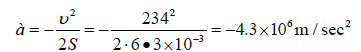 (5)
(5)
It does not only result in an electronic impulse in lead, but also in an impact (inertial) explosion of lead. The measured atomic or vapor fraction of lead that settles on the screens after striking dozens of bullets with a velocity of v = 234 m/sec averaged β = (Δm/m) × 100% ≈ 1.64% of the initial mass of the bullet. This value proves the fact of lead inertial explosion and is an objective reality rather than a measurement error.
The effect of such an explosion was confirmed by the video frames of the impact of a lead bullet (blunt-tip bullet "Gamo pro Match"), (Figure 6b). The velocity of the bullet at the time of contacting the steel target was v = 140 m/sec (shot from the air pistol). Video frames were recorded using camera «Phantom Miro M320 S». The exposure time for one frame is 1.63*10–5 sec, recording frequency 62015 fps. Upon impact on the target, one out of every twelve bullets, on the average, produced a distinct outburst of the explosion products of Figure 6b.

Figure 6: Lead bullet Gamo pro Match” (a), and the flash of lead inertial explosion products (b) upon hitting steel target; bullet mass 0.48 grams, diameter 4.5 mm, bullet velocity 140 m/sec; exposure duration 1.63‧10–5 sec; the bullet travels from the right to the left (b); the experiment was conducted by D.V. Dukhopelnikov and E.V. Vorobiev on 17.03.2017
The kinetic energy of each bullet atom at the moment of contact with the target is
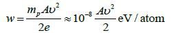 (6)
(6)
During the interaction with the target this energy is consumed to generate an electronic impulse in the bullet, to blow up all or a part of its mass by inertial explosion, to deform the bullet, to pierce a target or make a crater in it, etc. Let us estimate whether the energy (6) is sufficient for at least the electron impulse and the lead explosion. For this we substitute the atomic mass of lead A = 207 amu. in (6) and two values of the bullet velocity v1 = 234 m/sec and v2 = 140 m/sec, with the help of which both effects were obtained. The calculated values of the kinetic energy w1 = 0.0567 eV/atom and w2 = 0.0203 eV/atom matches with the imbalance energy εd, which resulted in the electric explosion of six different metals (Table 1). This match leads us to believe that these velocities are sufficient for providing an electronic impulse as well as for lead inertial explosion.
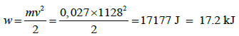
Some information about the temperature of lead explosion of products can be derived from the following experiment [19] (Figure 7). The video records of many experiments show that it is the vaporlike products of lead explosion that have the clearest border of the glow front (Figure 7d). Therefore, we assumed that the temperature of the vapor stream can be calculated based on the velocity vf of the propagation the glow boundary 5. In our experiment, a lead cylindrical projectile 2 of 14.5 mm diameter, 15.2 mm in length and a mass of 0.027 kg received its kinetic energy in a powder booster. After leaving the booster, the projectile approached target 2 at a velocity v = 1128 ± 14 m/sec. Video frames were recorded by a camera with the frequency of 25 000 fps and an exposure time of one frame of 1/156000 sec. The lead target 3 was a parallelepiped with the dimensions of 67 × 82 × 15.5 mm and a mass of 0.91 kg (Figure 7b). The mass of the target 1, remaining after the impact, was 0.68 kg (Figure 8). To get clear video frames, the target and the projectile track were illuminated with a 6-kW spotlight.

Figure 7: Video frames a, c and the scheme of projectile motion b and explosion shockwave front propagation d: 1 - wad; 2 - lead projectile; 3 - lead target; 4 - front surface of the target; 5 - glow front border; 6 - lead atom-vapor mixture glow; 7 - dark products of lead explosion; 8 - reverse side of the target; 9 - steel bearing plate; z1 = 21.7 mm - distance between projectile and target; z2= 22.6 mm - distance between the target and the explosion shockwave front; v = 1128±14 m/sec; vf - velocity of glow front propagation [19].
Using a very rough approximation, the stream of the atomicvapor mixture will be considered separately from the stream of lead dust and fragments near the target. The stream of the atomic-vapor mixture of lead is formed both in front of the target and behind it. In both cases, the dark 7 and the glow 6 components of the lead stream are clearly distinguishable. The difference in color and brightness of these components suggests that the vaporous products of the disintegration of lead have two thermal fractions: high-temperature 6 and low-temperature 7 (Figure 7d).
After processing a number of video frames, it was found that, firstly, the time of projectile 2 transition from the solid state to the glow atomic-vapor mixture 6 does not exceed Δτ ≤ 2*10–6 sec and, secondly, the front 5 propagation velocity of this mixture is vf ≈ 1210 m/sec at target surface 4 (z = 0). Thus, in spite of the difference in the causes leading to electrical, Section 2, and inertial, Section 3, explosions, the duration of both processes is approximately the same and amounts to the order of microseconds. On the other hand, there such parameters of the lead atomic-vapor stream observed in the experiment [19] as the shock waves, as well as the increase in the cross-sectional area of the flow with a decrease in its velocity, that suggest that the substance composing stream 5 and 6 (Figure 7d), is in the gaseous state and moves with the velocity of sound. We shall assumed the velocity of the atomic-vapor stream at the place of its generation (in the cross section z ≈ 0) equal to the velocity of sound, c = vf ≈ 1210 m/sec. It is related to the stream temperature T0 by the equation
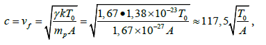 (7)
(7)
where γ ― heat capacity ratio of gas at constant pressure and at constant volume (γ = 1.67 for monatomic molecules lead vapor); k = 1.38 *10–23 J/K is the Boltzmann constant; mp = 1.67 *10–27 kg is the mass of the proton; A = 207 amu is the atomic mass of lead. The temperature T0 of atomic-vapor explosion lead product is calculated from equation (7):
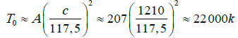 (8)
(8)
The kinetic energy of individual particles constituting vapor with temperature T0 is equivalent to the value:
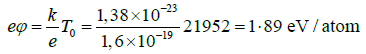 (9)
(9)
It differs from the cohesive energy of lead εPb = 2.04 eV/atom by only 7.3% (Table 1). This experimental fact counts in favor of two hypotheses at least. Firstly, the energy that caused inertial the explosion of lead is small, in the same order of magnitude as the energy imbalance εd of electrical explosion, (Section 2) and (Table 1). Secondly, the difference between the cohesive energy ε and the imbalance energy εd completely converts into kinetic energy of the vapor-like products of the metal explosion.
The kinetic energy brought by the projectile 2 to the target:
 (10)
(10)
The energy needed to evaporate the mass of target ΔM = 0.91– 0.68 = 0.23 kg is about EΔM = 215 kJ, (Figure 8). The fraction of the vapor phase 6 and 7 in the products of target explosion (Figure 7), is about 60% [19]. Since the energy necessary for evaporation lead target is greater than the kinetic energy of the projectile, 0.6‧EΔM >> w, there must exist a mechanism generating this additional energy. Section 4 describes this mechanism. Thus, the basic information about the inertial explosion is provided by the Tolman–Stewart experiment, according to which the deceleration (40 ... 560) m/sec2 is enough to generate a pulse of free electrons in a copper sample. The maximum sample velocity before deceleration is 63 m/sec.

Figure 8: Lead target after inertial explosion: 1 - remaining part of the target with the mass = 0.68 kg; 2 - outline of cylindrical lead projectile with diameter =14.5 mm and length =15.2 mm; 3 - outline of lead target 67 × 82 mm2 before the explosion, target thickness = 15.5 mm; (a) - target surface facing the projectile; (b) - view along arrow ÃÂ.
In the present work an electronic impulse formed in a lead bullet upon contacting with the target at the velocity v ≥ 120 m/sec. It has been shown that the velocity v = 140 m/sec is sufficient to cause a lead explosion, with the deceleration a amounting to a ≈ –106 m/ sec2. The duration of the electron impact impulse in the lead bullet is approximately equal to t1 ≈ 1‧10–7 sec. Inertial and electrical explosions of metal last much longer, Δτ ≈ 10-6 ... 10-5 sec, respectively. The temperature of the vapor products of the inertial lead explosion reaches 22000 K. If the speed of the lead projectile before the impact on the lead target is v = 1130 m/sec, both the projectile and the lead target explode. The kinetic energy of impact that provides lead inertial explosion is equal to εd = 0.0203 ... 0.0567 eV/atom, which corresponds to a rate of β = 0.99 ... 2.78% of the cohesive energy ε = 2.04 eV / atom of this metal. We were able obtain the same order of rate β for the electric explosion of metal films (Table 1). Yet, it remains to find out how the energy difference Δε = ε – εd, which appears during the inertial explosion of lead and other metals, is consumed (Section 4).
Energy of Inertial Explosion
The impact deforms and heats the metal. Fast deformation leads to inertial explosion of the metal. We consider that the reason for this effect is the formation of the flow of free electrons within the crystal lattice, which impairs the ability of these particles to "glue" the lattice sites into the crystalline solid frame (Figure 9). Freed from electronic guardianship, the ions fly out of lattice sites under the influence of pushing electric force (Coulomb burst or explosion [16]). The energy of this explosion destroys both the metal-projectile and the metaltarget (Section 3). As mentioned in Section 2, positive ions in the metal are in a fixed lattice sites, and negative electrons move chaotically among them as gas. Particles with opposite charges are attracted to each other by means of the cohesive energy ε (Figure 9a). The ions oscillate (phonon) at lattice sites serving as centers of equilibrium. As soon as the ion is removed from the site, its place is occupied by a negative electron, which returns the fugitive to its original position by its field (Figure 9b). If form a collective flow from the electronic chaos (electric current or heat flow, or inertial impulse upon impact [15]), they will weaken their binding ("glue") effect on ions. The ions will scatter in all directions, and the crystal will explode, releasing energy (Figure 9c). “By quantum theory any localization of electrons tends to increase the kinetic energy” of crystalline system and it breaks the balance of energy in the crystal [4]. Since the collective directed motion of electrons is equivalent to their localization in a crystal, it always generates metal explosion. Now Figure 9 is often met in the Internet, but for the first time it was published [20].

Figure 9: The diagram of departure from energy balance between free electrons and bound ions in the crystal lattice: a - chaotic motion of free electrons 1; b - periodic oscillations of ions 2 at lattice sites (phonons); c - electrons are localized in the flow 3 by an electric current or an electronic impulse, ions are allowed to fly apart under the action of Coulomb force [20].
Nature itself gives us an example of a similar phenomenon, which we named inertial explosion. In this manner, metal meteorite explodes when it hits the ground and forms a huge funnel. In search of numerical parameters confirming the probability of an inertial explosion, we turned to the data on the investigation of iron and nickel meteorites. The data demonstrated that an iron meteorite will "evaporate" or it will sublimate completely if the impact velocity is v > 4000 m/sec, and it will remain intact if v < 2000 m/sec. In the velocity range 2000 m/sec < v < 4000 m/sec, irreversible changes will occur only in a part of the meteorite, and the energy of the explosion will be smaller.
Based on the condition that the kinetic energy of the atoms of the projectile [6] should exceed the binding energy (w ≥ ε), we suggested the following rule [15]. An inertial explosion captures the entire volume of the projectile if its critical velocity vc satisfies inequality
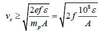 (11)
(11)
Here, ε is the cohesive energy of the metal bond, eV. The parameter f was named coefficient of impact efficiency. Its value is determined experimentally and lies in the range 0.075 < f < 1 [3]. Assuming f = 0.25 [15] let’s calculate the critical velocity (11) for some metals. The obtained results are written down in a row by the decreasing ability of the metal to an inertial explosion (Table 2). The first in Table 2 are Cs, Pb, Cd and Bi. These are the best materials for the experiment, since they disintegrate at a relatively low velocity of the projectile. However, Cs burns in the air, and Cd is toxic. Therefore, for our experiments we chose Pb and Bi. Nickel and Iron are located at the bottom of the table. For their disintegration, meteoritic velocity is needed. This effect is weakly expressed in the Aluminum and Beryllium. We emphasize that velocity vc, indicated in the Table 2, is only suitable for qualitative evaluation. Coefficient f itself being the basis for determining the order of vc, depends on many factors, e.g., on the projectile design. Besides, the cohesive energy used in this case is for pure metals [4], whereas for alloys it is less. Therefore, steel as an alloy of iron with other elements, should be placed above line 16 in Table 2 and the critical velocity for steel projectile is less than for iron one.
| S.No | Metals | Atomic mass ÃÂ, aum. | Cohesive energy e, eV/atom | Density r, kg/m3 | Critical velocity vc, m/s | |
|---|---|---|---|---|---|---|
| 1 | Cesium | Cs | 133 | 0,83 | 1873 | 558 |
| 2 | Lead | Pb | 207 | 2,04 | 11350 | 702 |
| 4 | Cadmium | Cd | 112 | 1,16 | 8650 | 718 |
| 3 | Bismuth | Bi | 209 | 2,15 | 9747 | 717 |
| 5 | Barium | Ba | 137 | 1,86 | 3594 | 823 |
| 6 | Zinc | Zn | 65 | 1,35 | 7133 | 1006 |
| 7 | Indium | In | 115 | 2,60 | 7310 | 1063 |
| 8 | Uranium | U | 238 | 5,40 | 18950 | 1066 |
| 9 | Tin | Sn | 119 | 3,12 | 5750 | 1145 |
| 10 | Tantalum | Ta | 181 | 8,09 | 16654 | 1495 |
| 11 | Tungsten | W | 184 | 8,66 | 19300 | 1535 |
| 12 | Copper | Cu | 64 | 3,50 | 8960 | 1660 |
| 13 | Zirconium | Zr | 91 | 6,32 | 6506 | 1863 |
| 14 | Molybdenum | Mo | 96 | 6,81 | 10220 | 1883 |
| 15 | Nickel | Ni | 59 | 4,43 | 8902 | 1944 |
| 16 | Iron | Fe | 56 | 4,29 | 7874 | 1960 |
| 17 | Niobium | Nb | 93 | 7,47 | 8570 | 2004 |
| 18 | Titanium | Ti | 48 | 4,85 | 4540 | 2249 |
| 19 | Aluminum | Al | 27 | 3,34 | 2698 | 2487 |
| 20 | Beryllium | Be | 9 | 3,33 | 1847 | 4301 |
Table 2: The critical velocity vc of the projectile leading to an inertial explosion of its metal (the impact efficiency coefficient is assumed equal to f = 0.25) [9].
The physical confirmation of the order of data in Table 2 we obtained as follows [9]. Let us assume that several identical projectiles from different metals hit the same target at the same velocity. If the projectile's metal is given at the top of Table 2, then the crater from it is larger than the crater made with the projectile from the other metal. This happens because most of the projectile explodes and more energy is released to destroy the target. Based on this assumption, we tested lead, steel and aluminum projectiles. They all had diameter of 14.5 mm, mass m = 0.0305 ... 0.0307 kg and a velocity of v = 1300 m/s (± 1.5%). As expected, the volumes of craters left by them had ratio as: lead (Pb) — 2.02; steel (Fe) — 1.53; duralumin (Al) — 1.00. The error in determining the craters volumes did not exceed 4%. In addition, the steel and lead projectiles had flat and conical surface facing the target. The crater left by the flat projectile was always greater than the conical one. In these experiments, the volumes of craters from lead projectiles had ratio as: flat (Pb) — 2.02; conical (Pb) — 1.66. Volumes from steel projectiles: flat (Fe) — 1.53; conical (Fe) — 1.26. Relationship of projectile form and the effect of the inertial explosion were noted earlier (Figures 5 and 6). The difference in the volume of craters corresponds to the position of the projectile's material in Table 2. This confirms, albeit indirectly, that as the result of the impact there was an inertial explosion of metal, and various additional energy was produced. Due to the difference in the amount of energy we obtain large volumes of some craters and smaller volumes of the others.
As far as we know, the additional energy release upon impact of metal was first noticed and measured by Dr. Yavorsky [17]. According to his results, the ratio of the thermal energy released in steel target to the kinetic energy brought by steel projectile into the target reached 4.12: 1. Velocity of the projectile was 1390 m/s, mass 4 kg. In the control experiments, steel projectiles were used, having a velocity of 1000 ... 1240 m/s. It was shown that the thermal energy of the target exceeded the kinetic energy of the projectile by 20% (the mass of the projectile was 0.0615 kg), and by 48% (the mass of the projectile was 0.0885 kg). The stability of the obtained results confirmed their reliability.
In experiments [21], target energy was measured by water calorimeter. We repeated the experiments of Yavorsky, but with projectiles of various metals [3,8,9,19,20]. Some of the experiments were done with flat open targets (Figure 10ð,ÑÂ). With their help the energy which necessary for the production of some products of a projectile explosion was determined. Other experiments were done with target-traps (Figure 10b). Such a target had a semi-closed hollow 8, in which not only fragments were detained, but also a part of the metallic vapor carrying an appreciable fraction of the energy of the explosion. The size and mass of the target allowed immerse it completely in a calorimeter with a minimum mass of water.
In experiments with an open target (Figure 10a), for example, a projectile with a mass of 0.0305 kg, having a lead core of 0.0225 kg and a steel beaker was used. Diameter of the projectile is 14.5 mm; velocity of meeting with the target is 1300 ± 20 m/sec. The thermal energy released as the result of an inertial lead explosion exceeded kinetic energy of the projectile by 2.18 times. For its determination, we took into account the heat measured by the calorimeter, as well as the energy of the fragments and the energy required to vaporize the disappeared part of the lead core [15].

Figure 10: Open target (a) with the crater produced by lead projectile, the diameter and height of the target are 75 and 50 mm, respectively, mass 1.65 kg, crater diameter 40 mm; (b) - the surface of the crater 4 in a randomly exploded target-trap; (c) - semi-closed target-trap: 1 - inlet hole for the projectile; 2 - the rear surface of the protective washer; 3 - front side of the target; 4 - surface of the crater; 5 - the projectile; 6 - border of the target; 7 - frontal surface of the protective washer; 8 - semi-enclosed cavity; weight of the target is 2.01 kg; both targets are made of steel.
In experiments with the target-trap, a Bismuth projectile was examined. The thermal energy measured in the target was 1.81 times greater than the kinetic energy of the projectile. The mass of the projectile is 0.0245 kg, diameter is 14.2 mm, and the velocity is 1183 ± 20 m /s. The mass of bismuth in the drummer is 0.016 kg. If the core of the projectile was from Indium, then the thermal energy of the explosion was 1.12 times greater than the kinetic energy of the projectile [15].
As follows from the law of conservation of energy, the only source that brings energy to the target is the kinetic energy w of the projectile. However, the experiment demonstrates that the total energy w + ΔE released in the target is much greater than w [8,15,21]. The presence of an excess of energy ΔE confirms the existence of an additional energy source, which is an inertial explosion of projectile (and in some cases, of the target metal):
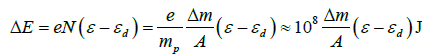 (12)
(12)
where N is the number of atoms of the metal that left the projectile as a result of the explosion; e is the cohesion energy, eV/ atom; εd — energy of imbalance, eV/atom (Table 1); Δm is the mass of the exploded metal, kg. Equation (12) determines the energy of an inertial explosion. For example, explosion of Δm = 0.001 kg of lead releases energy ΔÕ ≈ (108 ‧ 0.001 / 207) × (2.04 – ~ 0.02) ≈ 976 J.
In most of our experiments, the velocity of meeting with the target was v = 1100 ... 1300 m/sec, deceleration at impact a ≈ –2*107 m/s2. The maximum duration of lead explosion was not more than Δt ≈ 6.5*10–5 sec [15].
In the metals examined by us, the ability for electric and inertial explosion is the same (Table 3). It is seen that the critical current density jc increases with the transition from Tin to aluminum. These are our experimental data. In the same manner, the critical velocity of the projectiles also increases. This is the calculated parameter. The lower the density jc is or the lower the velocity vcr is, the easier the metal explodes. Thus, the trends of experimental and theoretical results repeat each other in five metals. The sixth metal, titanium, fell out of this row.
| Elements | Sn | W | Ti | Cu | Ni | Al |
|---|---|---|---|---|---|---|
| Current density jc, A/m2 | 1.32*109 | 1.43*109 | 3.78*109 | 7.29*109 | 7.41*109 | 8.04*109 |
| Critical velocity vc, m/s | 1145 | 1535 | 2249 | 1660 | 1944 | 2487 |
Table 3: Aptitude of various metals to electrical and inertial explosion.
Thus, any metal explodes due to the impact, releasing the energy of its inertial explosion. The energy released is less than the cohesive energy of the exploding metal. The efficiency of the explosion is different for different metals. The efficiency of the explosion depends both on the velocity of the projectile and on its design. The energy released by the explosion and its carriers — free electrons — not only heat the products of this explosion. We assume that they lead to nuclear transmutation of the projectile’s metal.
Possible Nuclear Transmutation as a Result of Mechanical Impact on Metal
It was shown in [2] that an inertial explosion of a metallic projectile causes the transmutation of bismuth nuclei entering the alloy of the latter. The projectile was a steel cup-shaped cylinder with diameter of 30 mm, a height of about 60 mm with a wall thickness of about 2 mm. inside the cup, a core of low-melting metal was flooded: lead, bismuth, eutectic bismuth alloy. The cylindrical core could also be steel or duralumin. All the cores hit the target with their flat open base. Bismuth, which was used in these experiments, meets to requirements of State Standard GOST 10928-90 (97-98 wt % Bi). The natural isotope 209Bi, which forms the basis of Bi2 bismuth, is the only stable isotope of this metal, while 34 other isotopes are radioactive. The material for most projectiles was the eutectic bismuth alloy 18 Pb – 49.4 Bi – 11.6 Sn – 21 In (wt %), (ρ = 9410 kg/m3, âm = 330 Ú) [22]. The speed of the projectile was determined from the video frames recorded by camera FASTCAM SA5 model 775K-M3 video camera [2]. The target material was AK25 steel containing ~95 wt % Fe and alloying elements (Ni, Cr, C, Si, Mn, Mo, Cu, S, P) [23]. Thickness of the target is 35 mm. The scheme of the experiment was the same as shown in Figure 7, but the steel target did not explode as lead one. By varying the speed, material and diameter of the projectile, we caused an inertial explosion of its core and knocked out the plug from the target (Figure 11). The explosion was accompanied be a flash in the region of contact between the projectile and the target.
From what has been said, it follows that neither the projectile nor the target had elements of platinum and boron in their composition. As a result of the interaction of the projectile with the target, a film of metallic condensate is formed at the site of their contact. The film remains intact on the rear surface of the knocked out plug (Figure 11). Composition of its chemical elements gives to us information about the possible change in the material of the projectile as a result of an inertial explosion. In addition, metal dust, which arose as a result of the explosion, is deposited in the area meeting of the projectile with target. Thus, the film remaining on the backside of the plug, as well as dust at the site of the explosion, there are two objects for investigating the products of the inertial explosion of the projectile. Unfortunately, in both cases, the mass of these products is not sufficient for ours mass-spectral analysis equipment.

Figure 11: Plug on which platinum and boron were detected in the condensate film caused by the inertial explosion that were knocked out by projectile made of Pb–Bi–Sn–In alloy, thickness of steel target 35 mm: a - backside plug surface 42 mm in diameter with a condensate film of Pb-Bi-Sn-In, traces of laser craters left by the LAES system are visible; b - enlarged image of the 25 craters on the area of 5.5 × 4.5 mm, the diameter of alone crater is ~0.7 mm; the velocity of the projectile v = 956 m/sec.
Four diagnostic groups and the following diagnostic equipment were used to identify products of an inertial explosion of a projectile containing bismuth.
1. XRF-1 is X-Rays Fluorescent spectrometer “Bruker S1 Titan” (produced by Bruker AXS Handled Inc., USA). This is relatively rough analysis method. The spectrometer detects platinum on the backside surfaces of all plugs obtained in experiments with bismuth. But the mass share of platinum is overestimated since platinum and bismuth lines are close in the X-ray spectrum of condensate.
2. XRF-2 (“EXP-1; XRF Experimenter’s Kit”) is X-ray fluorescence spectrometer (produced by Amptek Inc., USA). It is called the X-ray detecting system X-123SDD. This system consists of silicon drift detector (SDD) and Mini-X USB controlled X-Ray Tube. With the help of these instruments it becomes possible to recognize platinum lines position in condensate spectrum for the energy ranging from 8 up to 10 keV (Figure 12). The system detects as follows: platinum is 0.089 mg per 1 cm2 of condensate layer’s surface.

Figure 12: X-ray spectrum of the Pb-Bi-Sn-In alloy condensate deposited on steel plug (a, b is the same spectrum segment with separated lines of (a) Pt and (b) Bi; X-ray detection system X-123SDD (XRF-2); the contours of line 1 (Pt-Ll1) and 2 (Pt-Ln) belong to platinum and are not overlapped with the line of bismuth.
3. LAES is Laser-Atomic Emission Spectrometer LAES MATRIX SPECTROMETER for analyzing emission lines of laser plasma spectrum (plasma is generated from a condensate a condensate film of Pb-Bi-Sn-In by laser beam energy). The experiment shows that in the condensate spectrum there are four platinum lines with wavelengths of 201.534; 204.953; 214.402 and 224.592 nm. Boron line (206.571 nm) and platinum line (206.750 nm), which has no bismuth lines in the nearest neighbor, are clearly seen. The steel target, from which the plugs are knocked out, includes iron (216.175 nm and 206.367 nm), and copper cuprum (206.604 nm) and nickel (206.835 nm). The lines of these metals are sufficiently far from the boron line (206.571 nm) for distorting boron line formation. There are no boron and platinum in projectile and target composition, but their lines are clearly seen in the spectrum of products generated by their interaction.
4. SEM is Scanning Electron Microscope JSM-6060A (JEOL, Japan) with an energy dispersive attachment JED-2300 (JEOL, Japan) for recognizing boron in the condensate. SEM-diagnostic of plugs surface is performed only for confirming boron presence in condensate. Measurements are performed in ten points at the back surface of one plug. Each measurement shows boron presence with mass content ranging from 7.93% up to 11.20 %. Under examining another plug, eight points are probed. Boron presence with mass content ranging from 10.29% up to 15.76 % is detected in seven points. It is necessary to point out that it is difficult to perform quantitative micro-analysis of light elements (B, C, N, O) since lowenergy X-rays emitted by the sample is absorbed strongly. Hereby, this diagnostic equipment makes it possible to estimate boron presence in condensate only qualitatively.
The main disadvantage of elemental analysis of the inertial explosion condensate is as follows: the number of methods used for diagnostic is small; in particular, mass spectral method is not used. Another object of study was metallic dust at the site of the projectile explosion; see the beginning of this section. Metal dust was collected around the hole from the bismuth bullet in a steel target. The diameter of the bullet is 14.2 mm, weight 24.5 g, velocity v = 1210 ± 42 m/sec. Investigating the dust, we found the emission of four single ejections Alfa-particles with energy of about 8 MeV within 70 minutes after the explosion [10]. This experimental result serves as an additional argument in favor of the nuclear transmutation of bismuth induced by a mechanical impact. Thus, emission of α-particles and spectral analysis of interaction products shows that metallic bismuth transforms into metallic platinum and wide-gap semiconductor boron as a result of a mechanical impact.
The atomic mass of bismuth is ABi = 209 amu, the atomic mass of platinum is APt = 198 amu, and atomic mass of boron is AB = 11 amu. Platinum and boron was formed from bismuth in accordance with the suggested of radioactive series:
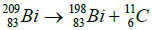
 (13)
(13)
Any nuclear transmutation (except radioactive decay) is caused by external factors that make it possible to overcome the nuclear binding energies. The binding energy of bismuth is approximately Wb ≈ 8 MeV/nucleon [22]. In our experiments the external factor for bismuth transmutation was the kinetic energy of the projectile per one atom, see equation (6):
 (14)
(14)
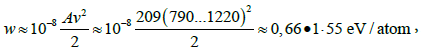
where v - the velocity of the studied projectiles. The peak of the energy density (14) can shift to the contact surface of the projectile and the target. At this point, the energy will reach its maximum
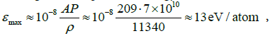 (15)
(15)
where P ≈ 5*1011 Pa ― the maximum pressure impulse in the contact plane of the projectile-target [23]; ABi = 209 amu - atomic mass of bismuth; ρ = 11340 kg/m3 is the density of bismuth.
However, this energy is clear insufficient for transmutation of bismuth nuclei, 
The impact damages the natural protection of the nucleus 209Bi against external effects provided by electronic shell structure of atoms. The protection becomes deficient if an external force shifts the electrons with respect to the nucleus of bismuth [24].
Conclusion
As shown by experiment, electrons are indeed shifted during the deceleration of the projectile at the rate of –6*107 m/sec2, with the directed electron flow exploding the cold metal. For an atom with degraded electron protection the nuclear equilibrium is upset and stable bismuth is transformed into one of its radioactive isotopes. Radioactive decay reaction is triggered. In case of bismuth it will proceed in the form of orbital electron nuclear capture [25,26], and will be finished when the stable elements platinum and boron are obtained.
References
- Marakhtanov MK (2017) Impact atom emission. J mater sci res 6: 1-4.
- Marakhtanov MK (2016) Possible nuclear decay of bismuth induced by a mechanical impact. Russian Metallurgy (Metally) 9: 884-888.
- Ãœðrakhtanov ÃœÚ (2005) Russia Patent № 2260779. RU, G01 L5/14, F42 B 12/02
- Kittel C (1971) Introduction to Solid State Physics (4th Edition). John Wiley Publishing, New York.
- Ãœðrakhtanov ÃœÚ, Ãœðrakhtanov ÃÂÃÂœ (2005) Russia Patent № 2296168. RU, C2, C21D 1/34, C22F 1/00
- Ãœðrakhtanov ÃœÚ, Ãœðrakhtanov ÃÂÃÂœ (2000) Electrical explosion of cold thin metal films.Thin Solid Films 359: 127-135.
- Ãœðrakhtanov ÃœÚ, Veldanov VA, Duhopel’nikov DV, Tarasov MA(2012) The electronic impulse grown inside the lead bullet on impact. Jour Arms Policy Conversion 1: 21-24.
- Ãœðrakhtanov ÃœÚ (2009) Metals as an energy source. Izv Ross Acad Nauk Ser Energetika 1: 79–-91.
- Ãœðrakhtanov ÃœÚ, Veldanov VA, Maximov MA, Tarasov MA (2009) Some features of the interaction of a metal projectile with a metal target. Izvestiya RARAN 1: 43-53.
- Baranov DS, Baranova OD, Duhopel’nikov DV, Ãœðrakhtanov ÃœÚ (2015) Impact of a bismuth bullet. Proceed eight all-Russian conf Izd 1: 248-252.
- McGrath JR (1966) Exploding Wire Research 1774 - 1963 US. Naval Research Laboratory, Washington, DC.
- Exploding-bridgewire detonator–Wikipedia. https://en.wikipedia.org/wiki/Exploding-bridgewire_detonator.
- Zernov L, Wright F, Woffinden G (1962) High-speed Cinemicrographic Studies of electrically Exploded Metal Films. Exploding Wires 2: 245-262.
- Sarkisov GS, Struve KV, McDaniel DH (2004) Effect of current rate on energy deposition into exploding metal wires in vacuum. Physics of Plasmas 11: 4573–4581.
- Ãœðrakhtanov ÃœÚ, Ãœðrakhtanov ÃÂÃÂœ (2013) Quantum Macroelectronics: Experiment and Theory. KRASAND, Moscow.
- Duhopel’nikov DV, Kalashnikov NP, Ãœðrakhtanov ÃœÚ, Ãœðrakhtanov ÃÂÃÂœ (2010) Coulomb burst of metal wires. Nuclear Phys Eng 1: 339–346.
- Tolman RC, Stewart TD (1916) The electromotive force produced by the acceleration of metals. The Physical Review 8: 97–116.
- Ãœðrakhtanov ÃÂœ Ú,Veldanov VA, Duhopel’nikov DV, Tarasov MA (2012) The electronic impulse grown inside the lead bullet on impact. Jour Arms Policy Conversion 1: 21–24.
- Ãœðrakhtanov ÃœÚ,Veldanov VA, Duhopel’nikov DV, Karneichik AS, Krutov IS, Makarov AA (2017) Modeling a spacecraft fracture mechanism occurring as a result of its metal components inertial explosion at collision. Vestnic Moscowskogo aviatsionnogo institute 24: 17–25
- Ãœðrakhtanov ÃœÚ, Ãœðrakhtanov ÃÂÃÂœ (2002) Metal explodes. Science and life 4: 16–19.
- Yavorsky VV (1998) Energy from “out of nowhere”. Science and life 10: 78–79.
- Grigoryev IS, Meilihov EZ (1991) The physical magnitudes (Reference book). Energoatomizdat, Moscow.
- Orlenko LP (2008) Physics of explosion and impact. PhysMath Literature, Moscow. Russia.
- Okunev VS (2015) The basis of applied nuclear physics and introduction into physics of nuclear reactors. Izdatel. BMSTU, Moscow. Russia.
- Marakhtanov MK, Okunev VS (2016) Influence of mechanical collision macro objects on nuclear-physical properties of components of their nuclides. Herald of the BMSTU 1: 61–75, Moscow. Russia.
- Oganessian YuTs, Rykaczewski KP (2015) A beachhead on island of stability. Physics Today 68: 32–38.