Spanish
  Chinese
  Russian
  German
  French
  Japanese
  Portuguese
  Hindi
Hindi Review Article, J Ind Electron Appl Vol: 4 Issue: 1
An Intelligent IoT-Based Control System for Harnessing Hydropower Energy from Wake Induced Vibration
Derakhshandeh JF1*, Gharib N2 and Hadipour M3
1College of Engineering and Technology, American University of the Middle East, Kuwait
2Department of Mechanical Engineering, McGill University, Montreal, Quebec, Canada
3Department of Electrical Engineering, Hamedan Branch, Islamic Azad University, Hamedan, Iran
*Corresponding Author : Javad Farrokhi Derakhshandeh, College of Engineering
and Technology
American University of the Middle East, Kuwait
Tel: +965 2225
1400; E-mail: Javad.Farrokhi@aum.edu.kw
Received: December 02, 2019 Accepted: December 20, 2019 Published: December 31, 2019
Citation: Derakhshandeh JF, Gharib N, Hadipour M (2019) An Intelligent IoT-Based Control System for Harnessing Hydropower Energy from Wake Induced Vibration. J Ind Electron Appl 3:1. doi pending
Abstract
In this study, a new intelligent control system converter (ICSC) is developed, designed, and introduced in order to harness the hydrokinetic energy of wake induced vibration (WIV) phenomenon and convert it to the electricity. The WIV converter consists of tandem circular cylinders, while the upstream cylinder is stationary and the downstream one is mounted on an elastic structure. ICSC was designed based on the maximizing dynamic response of the downstream cylinder under the WIV phenomenon. Therefore, the structural parameters of the WIV converter, such as position and mass and damping ratios of the converter can be automatically and remotely controlled to maximize the oscillation of the cylinder based on the free stream velocity. The position of the downstream cylinder can be set at a desirable longitudinal and transverse distances in the wake of the upstream cylinder remotely via the Internet of Things (IoT) technology. Furthermore, the mass, the spring stiffness, and the damper can be set via a virtual mass-spring-damper mechanism (VMSD) Derakhshandeh et al. In a real-time. ICSC guarantees that all structural parameters are set suitably and appropriately to optimize the power coefficient of the WIV converter.
Keywords: Wake induced vibration; IoT technology; Ocean energy; Real-time control; Arduino; Circular cylinder; Renewable energy
Introduction
Flow/Vortex/Wake Induced Vibration (FIV/VIV/WIV) is a relatively new technique to harness hydrokinetic energy from oceans and still required more development. In this technique, the VIV/WIV converter captures the vortices’ energy of the stream and converts it to environmentally friendly energy such as electricity (Figure 1) [1,2].

Figure 1: Nomenclature.
An extensive studies have been dedicated to investigate VIV of a single circular cylinder in the literature and researchers have been investigated the interactions of the fluid and cylinder in details such as the maximum amplitude of oscillation, the resonance frequency and the effects of the mass and damping ratios [3-6]. The mass ratio is defined as the ratio of the mass of the cylinder and its components to the displaced mass of the fluid. It can be calculated by m*=4m/ ρπD2L based on the mass (m), the diameter (D), and the length (L) of the cylinder. The damping ratio (ζ) characterizes the frequency response of the system and can be expressed by the level of damping in a system relative to critical damping, which means ζ=c/cc. In the VIV phenomenon, the maximum amplitude of oscillation of the cylinder was found to be approximately one diameter at a wide range of reduced velocities, Ur=U/(fnD) where U represents the free stream velocity, fn stands for the natural frequency of the cylinder [3].
Methodology
In tandem cylinders, due to the effects of the upstream cylinder on the downstream one, the WIV mechanism can occur, and the complexity of the interaction between the fluid and structure increases as compared with VIV of a cylinder. The dynamic responses of the downstream elastic cylinder were studied by [4-11] in details using water channel tests. For two circular cylinders arranged in tandem, it was found that the wake of the upstream cylinder is significantly dependent on the streamwise separation between the cylinders and the resulting flow can be categorized into six different patterns [8]. This outcome has been confirmed later by [12-14]. Experimental tests of [7] at Re = 2.1×10³-105 showed that the flow regime could be classified as an overshoot regime when x0<1.2-1.8 as a function of Re. It was also found that at 1.2–1.8< x0< 3.5–4.0 , the reattachment regime is produced, in which the shear layers individually separating from both sides of the upstream cylinder and reattach to the downstream one. Finally, at a larger distance, where x0> 3.5–4.0, the shear layers shed vortices freely and do not attach to the downstream cylinder, which is known as co-shedding regime [7]. The effect of longitudinal distance has been also confirmed by other scholars [1,8,11,13-17]. As is well known, the dynamic behavior and flow structure around tandem circular cylinders significantly depend on the spacing ratio between the cylinders. In most of the previous studies, the fluidic instabilities, such as the shear forces imposing on the circular cylinders, the phase lag between vortices, and the variation of the Strouhal number have been studied. Consistent with the literature, at the critical spacing ratio [11], the phase lag and flow pattern may significantly alter, which can affect the surface pressure and consequently lift force induced on the cylinder. In addition, vortex shedding frequency or Strouhal number jumps abruptly, approximately from 0.12 to 0.18 values [11]. It was found that the maximum sufficient gap between cylinders is approximately 4D to guarantee that vortices are generated in the wake of the upstream cylinder [11]. In addition, at this range of gap, depending on the free stream velocity of the flow, the Strouhal number (St) varies, and it is not constant.
Assi [9] showed that when 3.5<x0/D<4.5, the downstream cylinder is significantly under the effect of the upstream cylinder. It was found that this optimum longitudinal distance is dependent on the reduced velocity. It was demonstrated that in the WIV mechanism at a highly reduced velocity, Ur>17 , the amplitude of oscillation is much higher than that observed for the VIV response of a single.
While the longitudinal distance between cylinders affects the downstream cylinder, the transverse distance between cylinders significantly influences the dynamic response of the downstream cylinder. Derakhshandeh et al. [18-20] found that the imposed lift force on the downstream cylinder due to the upstream vortices varies due to the phase lag of the vortices. At a limited range of Reynolds number (Re = ρUD∕μ), e.g., Re = 4-10 × 103. It was found that at the lower Reynolds number cases, the phase lag between lift force and displacement of the downstream cylinder is smaller compared to the higher Reynolds number tests. Furthermore, it was observed that the minimum phase lag between lift force and displacement occurs when 3.5<x0/D<4.5 and 1.0<y0/D<2.0 . Hence, to harvest maximum energy using the WIV phenomenon, the distance between tandem cylinders should be set at the most effective length based on the literature.
The oscillation of the elastically mounted cylinder with one-degree of freedom in y-direction (normal to the flow direction as shown in Figure 2 for VIV or WIV can be formulated as follow Williamson and Govardhan [21]:

Figure 2: Schematic of the WIV mechanism with a flow direction; the upstream cylinder is stationary while the downstream one is elastically mounted.

Where, m and c are structural mass and damping, respectively; k represents spring constant, and F stands for fluid force in the transverse direction. The transverse applied force on the cylinder and oscillation response of the cylinder can be evaluated as follow:
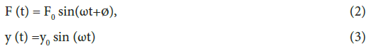
Here, ω is an angular velocity. It is a function of the frequency (f) of the oscillation of the cylinder and ω = 2πf.
It is seen that the oscillation of the cylinder is dependent on the structural parameters such as m, c, and k. Effects of these parameters have been studied excellently in the literature [3-5,17]. Derakhshandeh et al. [1] designed and used a virtual mass-springdamper (VMSD) mechanism to facilitate the setup of the structural parameters using a Simulink program and a MATLAB code. The virtual elastic mechanism consisted of a motor and a controller, a beltpulley transmission system and a carriage. In comparison with the more traditional mechanical impedance mechanisms, comprising of a real spring and damper system, the virtual mechanism, utilized in this work, provided greater flexibility and facilitated to set the parameters of the system, such as stiffness, damper, and mass. Furthermore, it has been shown that the fluidic parameter such as the frequency of vortices, which is a function of the Reynolds number has a significant effect on VIV [22-25]. A series of experimental tests conducted by Raghavan and Bernitsas [26] found that in Transition-in-Shear-Layer (TrSL), regime the amplitude of oscillation of the cylinder increases, and maximum energy of vortices can be achieved.
Instantaneous dynamic behavior of the downstream elastically mounted cylinder depends on both free stream velocity, the position of the cylinder structural parameters. Thus, Setup the converter with tandem cylinders to maximize the oscillation of the downstream cylinder is one of the biggest challenges in particular in deep oceans and consequently, designing and employing an intelligent control system which can be employed remotely will provide us a better achievement in harnessing the energy of the vortices using WIV mechanism.
As the fluidic conditions of streams and ocean currents such as free stream velocity are not stable, the arrangement of cylinders should be set according to the new environmental conditions. One of the best solutions can be considered and introduced as real-time control of the capability via networked infrastructure, which facilitates a platform for the connection of the different devices to a number of data source employing Internet of Things (IoT) technology [27-29]. Using a smart and intelligent control system for the WIV converter based on the alteration of the environment with a sensory application via IoT will solve and overcome the above problem.
To the best of the authors’ knowledge, there is no existing Automatic Scheme of Arrangement of Bluff bodies (ASAB) or sensory system to be able to set the arrangement of the cylinders in the WIV converter remotely based on the conditions of the free stream. This attention yields to innovate an Intelligent Control System Converter (ICSC) for WIV, which is not only able to set both structural parameters using the VMSD system but also the arrangement of the cylinders through ASAB. The structural parameters include the longitudinal and transverse distances between the cylinders, the mass and damping ratios, and the spring stiffness.
In the next section, the details of the mechanical and electrical mechanism of ICSC is introduced. The regulation of the structural parameters of the WIV converter can be conducted remotely according to the conditions of the under-layer flow streams of oceans and explained in detail.
Control System Including ASAB and VMSD Mechanism
The mechanism of setting the arrangement of the cylinders is shown in Figure 3. The figure shows the schematic of the Automatic Scheme of Arrangement of Bluff bodies (ASAB). In ASAB, the position of the downstream cylinder can be set automatically in x and y directions based on the predefined command. This command was programmed according to the best achievable reduced velocity of the free stream. ASAB consists of two rails and stepper motors, which are connected to the micro-controller. The capacity of the stepper motors in x and y directions can be evaluated based on the stagnation and static pressure of the fluid or water, respectively.

Figure 3: a) 2D schematic of the arrangement of the upstream and downstream cylinders; the downstream cylinder can move in both x and y directions simultaneously, b) 3D schematic of the mechanism including two stepper motors and downstream cylinder

Figure 3: c) Real platform of the ASAB.
Therefore, for horizontal movement of the downstream cylinder, the stagnation pressure is considered as follow:

where, is the density of the water, U represents the free stream velocity, and P stands for the static pressure. The maximum static pressure also should be considered for evaluating the capacity of the stepper motor in the y-direction as follow:

In Equation 2, g is the gravity and h is the height of the water column see Figure 2. Therefore, the minimum applied force on the downstream cylinder can be calculated as:

Here, A is the projection area of the downstream cylinder (DL).
To design the capacity of the stepper motor in y-direction, the weight of the cylinder should be considered and added to the fluid force to find the total force, which is applied on the motor. Thus, FTotal =Ff+W=Ff+mg. Consequently, the mechanical power can be written as:

where, T and r represent the torque and the radius of the shaft of the stepper motor, respectively. Hence, the minimum electrical capacity of the motor can be evaluated by adding the mechanical power to the power losses as follow, in which the power losses can be considered as frictional losses and power losses:

The best location of the downstream cylinder can be automatically identified by sensors according to the flow direction and the flow velocity and can be controlled via the IoT technology or GSM Network. The whole mechanism of the downstream cylinder can be set on a VMSD mechanism. The VMSD system consists of the whole mechanism of ASAB, which is mounted on a carriage. The carriage is driven by a toothed belt, which is coupled to two toothed pulleys, one pulley with free-acting as an idler, and the second one is coupled to a brushless servo-motor via a gearbox [1]. The details of VMSD is not repeated in this article. Therefore, the whole mechanism assists in controlling the arrangement of the cylinders as well as the parameters of the structure, such as mass and damping ratios.
Figure 4 depicts the flowchart of the control system of the proposed mechanism. The mechanism consists of two stepper motors, which drive remotely via IoT technology. The functionality of Acoustic Doppler Velocimetry (ADV) or water flow sensors assists to record the instantaneous components of velocity at a single point in a shallow current or even in a deep ocean, which is not accessible easily. Thus, the magnitude and direction of the velocity can be recognized by sensors automatically. Then, this information can be transferred to the Arduino board; and finally, the stepper motors will receive the command to arrange the gap between the cylinders at a suitable x0 and y0 positions. It is important to note that both ADV and water flow sensors should be able to transfer the commands via the wireless or wired network system. This facilitates monitoring the location of the downstream cylinder appropriately and remotely.

Figure 4: Flowchart of the ICSC including two stepper motors and VMSD to set the location of the downstream cylinder and structural parameters via the IoT platform.
While the stepper motors receive the commands and the position of the downstream cylinder is fixed, the structural parameters such as mass, spring stiffness, and damping ratio can be remote via IoT using the VMSD mechanism. The VMSD system is shown in Figure 4 in a blue dot point box. Controlling the system via IoT allows the operators to set the structural parameters of WIV remotely. In addition, the arrangement of the cylinder can be automatically set at optimum arrangement based on the free stream velocity of the current, which can be programmed in the Arduino microchip controller. The ICSC, therefore, automatically maximizes the dynamic response of the WIV converter and eliminates any manual setup or infrastructure development. Consequently, the efficiency of the converter increases, and it shortens the time and reduces the cost of the real MSD system. The operator can directly communicate with ICSC and provides storage to collect data, transmit and study things events to maximize the energy of the vortices, which can be captured [30,31].
To display all information such as the direction and velocity of the flow, the liquid crystal display (LCD) can be employed in the control system. Consequently, the operator is able to follow all commands, which are transferred or received to the mechanism.
The details of the circuits and connections are shown in Figure 5. As shown in the figure, the control system consists of SIM900A GSM Module, Arduino unit, a water flow sensor or Acoustic Doppler Current Profiler, two stepper motors, two Easy drivers, power supply, and mobile system. Table 1 indicates the technical information of the apparatus associated with Figure 5. It is observed that all commands comprising inputs and outputs will be sent/received to/ into the micro-controller inside the Arduino board within the GSM network platform via SIM900A module [32]. It is worth noting that other modules can be employed, such as SIM 800 and SIM900. Then, the receiving commands are analyzed and transferred to the relative apparatus, such as stepper motors. The commands can be sent with the wireless network or wired system. After processing the commands by the controller, a command then will be sent to the stepper motor. The motor was running by 24/12 V DC supplier, which is produced by an IC voltage regulator that takes in input, step it down and consequently, provide stable DC output. The stepper motors will set the position of the downstream cylinder in both x and y-directions according to the best-reduced velocity, which might vary at each condition. The structural parameters can also be set via SMS using the VMSD mechanism remotely. The connections of the sensors are highlighted in Figure 5 in red and black colors.
| No | Apparatus | Technical information/ Capacity |
|---|---|---|
| 1 | Stepper motor 1, 2 | Step Angle 1.8, Holding Torque: 5.96/10 kg/cm |
| 2 | ADCP sensor OR Water flow sensor | Acoustic Doppler current profiler |
| 3 | Arduino board | Digital I/O pins 14: (ATmega328) |
| 4 | Power supply | 12/24 VDC, 10-25 A |
| 5 | GSM Module, SIM900A GSM Module | 900A,900,800A |
| 6 | VMSD (see Derakhshandeh et al. 2015) | Consists of the carriage, timing belt, pulleys, and servo motor |
| 7 | Mobile Ring/SMS | SIM800/900 |
| 8 | Easy drive 1 and 2 | Easy Driver v 4.3-4.5, Stepper Motor Driver |
Table 1: Technical information of the apparatus associated with Figure 4.

Figure 5: Description of the connections of two stepper motors in x and y directions employing GMS Network system comprising ADV and water flow sensor.
Results and Discussion
It is important noting that in the proposed control system, the system can be controlled via two methods: 1) control the system remotely via the internet, 2) automatic commands from the stream velocity via the sensor, or ADCP. In the first system, the control method can be conducted by the operator based on the desirable commands, while in the second one, the position of the downstream cylinder is automatically set according to the range of stream velocity, which senses by the sensors. The automatic method is beneficial when there are some problems with internet access or no access to internet service.
If due to some issues, the stepper motors have not received any commands automatically, the operator is also able to run the motors remotely and set the arrangement of the cylinders via SMS, which can be transferred to the Arduino board via GSM system [33]. The operator can use the recorded information of the stream velocity and apply them for setting the arrangement of the cylinders. This information or command can be sent to three outputs including, stepper motor 1 for setting the position of the cylinder in the x-direction, stepper motor 2 for setting the cylinder in the y-direction, and VMSD mechanism, respectively.
Both motors can be run by a 24/12 V DC supplier, in which the amount of voltage varies based on the essential current of the motors. The power supply can be set outside the system, or a part of the produced energy can be used for running the system as input energy [34]. The errors of the mechanism also will be evaluated from the control room by monitoring the system. Furthermore, the dynamic behavior of the mechanism will be checked and controlled via monitoring the results by the operator [35].
Conclusion
In this paper, a new Intelligent Control System Converter (ICSC) was designed and introduced to maximize the captured energy of the WIV converter using the Internet of Things (IoT) technology. ICSC consists of two individual mechanisms known as ASAB and VMSD. Due to the influence of the structural and fluidic parameters on the WIV response, there was an attempt to set all the above parameters suitably, quickly and remotely. ICSC has this capability to set all these parameters even at not easily accessible fields, such as deep oceans. As a result, the maximum energy of vortices due to the wake of the upstream cylinder can be captured by ICSC. The proposed control system is very promising and provides the following benefits:
1. Stepper motors can be run via SIM800, SIM900, and SIM900A and based on IoT technology for VIV and WIV converter.
2. The application of the ater flow sensor or ADCP automatically and remotely for WIV converter.
3. Setup the effective parameters of the WIV using the VMSD remotely via Arduino micro-controller or control room rapidly.
4. Sending the commands via wireless or wired systems.
5. Using a part of the produced energy for as a power supplier system.
6. Monitoring and controlling the performance of the WIV converter in a real-time.
References
- Derakhshandeh JF, Arjomandi M, Dally B, Cazzolato B (2015) Harnessing hydro-kinetic energy from wake-induced vibration using virtual mass spring damper system. Journal of Ocean Engineering 108: 115-128.
- Bernitsas M, Raghavan K (2004) Converter of current/tide/wave energy. ProvisionalPatent Application. United States Patent and Trademark Office Serial.
- Bearman PW (1984) Vortex shedding from oscillating bluff bodies. Fluid Mechanics 16: 195-222.
- Govardhan R, Williamson C (2000) Modes of vortex formation and frequency response of a freely vibrating cylinder. Journal of Fluid Mechanics 420: 85-130.
- Govardhan R, Williamson C (2004) Critical mass in vortex-induced vibration of a cylinder. European Journal of Mechanics-B/Fluids 23: 17-27.
- Derakhshandeh JF, Alam MM (2019) A review of bluff body wakes, Ocean Engineering 182: pp: 475-488.
- Zdravkovich MM, Pridden DL (1977) Interference between two circular cylinders; series of unexpected discontinuities. Journal of Wind Engineering and Industrial Aerodynamics 2: 255-270.
- Igarashi T (1981) Characteristics of the flow around two circular cylinders arranged in tandem. I. JSME Int J Ser B24, 323–331.
- Assi G (2009) Mechanisms for flow-induced vibration of interfering bluff bodies. PhD thesis, Imperial College London, UK.
- Derakhshandeh JF, Arjomandi M, Cazzolato B, Dally B (2014) The effect of arrangements of two circular cylinders on the maximum efficiency of Vortex-Induced Vibration power using a Scale-Adaptive Simulation model. Journal of Fluids and Structures 49: 654-666.
- Zhou Y, Alam MM (2016) Wake of two interacting circular cylinders: a review. Int J Heat Fluid Flow 62: 510–537.
- Zdravkovich MM (1988) Review of interference-induced oscillations in flow past two circular cylinders in various arrangements. Journal of Wind Engineering and Industrial Aerodynamics 28: 183-200.
- Carmo BS (2005) Estudo numerico do escoamento ao redor de cilindros alinhados. Master's thesis, University of Sao Paulo, Brazil.
- Carmo BS, Sherwin SJ, Bearman PW, Willden RHJ (2008) Wake transition in the flow around two circular cylinders in staggered arrangements. Journal of Fluid Mechanics 597: 1-30.
- Assi G, Meneghini J, Aranha J, Bearman P (2006) Experimental investigation of flow-induced vibration interference between two circular cylinders, Journal of Fluids and Structures 22:819-827.
- Sumner D (2010) Two circular cylinders in cross-flow: a review. J Fluids Struct 26: 849–899.
- Alam MM, Meyer JP (2011) Two interacting cylinders in cross flow. Phys Rev 84, 056304–056316.
- Derakhshandeh JF, Arjomandi M, Dally B, Cazzolato B (2014) Effect of a rigid wall on the vortex induced vibration of two staggered circular cylinders, Journal of Renewable and Sustainable Energy.
- Derakhshandeh J F, Arjomandi M, Dally B, Cazzolato B (2014) Experimental and Computational Investigation of Wake Induced Vibration, 19th Australasian Fluid Mechanics Conference, Melbourne.
- Derakhshandeh JF, Arjomandi M, Dally B, Cazzolato B (2016) Flow induced vibration of an elastically mounted airfoil under the influence of oncoming vortices. Journal of Experimental Thermal and Fluid Science 74: 58-72.
- Williamson CHK, Govardhan R (2004) Vortex-induced vibrations, Annual Review. Fluid Mechanics 36: 413-455.
- Anagnostopoulos P, and Bearman P (1992) Response characteristics of a vortex-excited cylinder at low Reynolds numbers. Journal of Fluids and Structures 6: 39-50.
- Vikestad K (1998) Multi-frequency response of a cylinder subjected to vortex shedding and support motions: Department of Marine Structures, Faculty of Marine Technology, PhD thesis, Norwegian University of Science and Technology.
- Ding Z, Balasubramanian S, Lokken R, Yung T (2004) Lift and damping characteristics of bare and straked cylinders at riser scale reynolds numbersed. Proceeding of Offshore Technology Conference Paper No. 16341.
- Bernitsas MM, Raghavan K, Ben-Simon Y, Garcia E (2008) VIVACE (Vortex Induced Vibration Aquatic Clean Energy): A new concept in generation of clean and renewable energy from fluid flow. Journal of Offshore Mechanics and Arctic Engineering 130: 1-15.
- Raghavan K, Bernitsas MM (2011) Experimental investigation of Reynolds number effect on vortex induced vibration of rigid circular cylinder on elastic supports. Ocean Engineering 38: 719-731.
- Jin J, Gubbib J, Marusicb S, Palaniswami M (2012) An information framework of creating smart city through internet of things. IEEE Internet of Things 1: 1-10.
- Hadipour M, Derakhshandeh JF, Shiran MA, Rezaei R (2018) Automatic washing system of LED street lighting via Internet of Things. Internet of Things 1: 74-80.
- Hadipour M, Derakhshandeh JF, Shiran MA (2019) An experimental setup of multi-intelligent control system (MICS) of water management using the Internet of Things (IoT). ISA Transactions.
- Alam MM, Zheng Q, Derakhshandeh JF, Rehman S, Chunning J ( 2017) On forces and phase lags between vortex sheddings from three tandem cylinders. International Journal of Heat and Fluid Flow 69: 117-135.
- Assi G, Bearman P, Meneghini J (2010) On the wake-induced vibration of tandem circular cylinders: The vortex interaction excitation mechanism. Journal of Fluid Mechanics 661: 365-401.
- Astrom KJ, Hagglund T (2006) Advanced PID control, ISA.
- Åström KJ, Hägglund T (2001) The future of pid control. Control Engineering Practice 9: 1163-1175.
- Chang CCJ, Ajith Kumar R, Bernitsas MM (2011) VIV and galloping of single circular cylinder with surface roughness at 3.0 × 10⁴
- Derakhshandeh JF, Alam MM (2017) Flow structures around a rectangular cylinder in the vicinity of a wall, Wind and Structures. ASEM 26: 293-304.