Spanish
  Chinese
  Russian
  German
  French
  Japanese
  Portuguese
  Hindi
Hindi Research Article, Biomater Med Appl Vol: 1 Issue: 1
Computational Analysis of the Design and Experimental Application of the Migration and Durability Testing Device for Oesophageal Stent
Batgerel Tumurbaatar1,2, Ludwig Erik Aguilar1, Chan-Hee Park1,3* and Cheol Sang Kim1,3*
1Department of Bionanoystem Engineering, Chonbuk National University, Jeonju, Jeonbuk, Korea
2Power Engineering School, Mongolian University of Science and Technology, Ulaanbaatar, Mongolia
3Department of Mechanical Design Engineering, Chonbuk National Univerisity, Jeonju, Jeonbuk, Korea
*Corresponding Authors : Cheol Sang Kim
Department of Bionanoystem Engineering, Chonbuk National University, Jeonju, Jeonbuk, Korea
Tel: +82-63-270-4284
Fax: +82-63-270-2460
E-mail: biochan@nate.com
Chan Hee Park
Department of Bionanoystem Engineering, Chonbuk National University, Jeonju, Jeonbuk, Korea
Tel: +82-63- 270-4284
Fax: +82-63-270-2460
E-mail: biochan@jbnu.ac.kr
Received: September 22, 2017 Accepted: October 06, 2017 Published: October 10, 2017
Citation: Tumurbaatar B, Aguilar LE, Park C, Kim CS (2017) Computational Analysis of the Design and Experimental Application of the Migration and Durability Testing Device for Oesophageal Stent. Biomater Med Appl 1:1.
Abstract
An oesophageal stent durability/migration testing device was developed based on the mathematical analysis of durability mechanism of an oesophageal stent and oesophageal motility, in which the oesophageal stent was assumed to be under simulated in vivo pre compression load, in vivo creep load and internal environment. Hardware and software simulating an oesophageal tube movement was developed, which consists of six sensors, an Arduino MEGA and LabVIEW LIFO interface. Accurate detection of stent migration in an oesophageal model using camera image
processing analysis and Flexi force Pressure Sensor (FPS) combine was done. The control board for the real time monitoring of non-vascular oesophageal stents used Arduino MEGA2560. LabVIEW was used to monitor in real time the FPS and bend sensor,camera image processing on the stent durability/migration testing device. The testing results can verify the design of stent’s fatigue life and to ensure the records for the optimization of oesophagus stent design, this can ensure the trustworthiness of oesophagus stent implantation in vivo. This device could further evaluate the effectivity for all type of stents on non-vascular applications and also to test experimental materials on stents. Also, the said device can be modified and applied to test the migration and fatigue life of other GI stents.
Keywords: Oesophageal Stent; Durability and Fatigue; Stent Migration; In-vitro Testing Device; Arduino; LIFA
Introduction
The oesophagus is a long tube in the upper gastrointestinal system for passage of macerated food; it actively transports the food bolus by peristaltic movement. However, in cases of dysphagia that is brought about by cancer, the passage of bolus can be interrupted and cause severe complications to the patient. The main course of action for physicians is with stenting, Stenting can create patency in the oesophagus, ensuring proper passage of food to the stomach. However, this method of palliative treatment is doesn’t come without setbacks, one of which is migration of the implanted stent due to the constant peristaltic wave in the oesophagus, this can dislodge the stent to the stomach and can cause severe problems. With the development of materials technology, metallic and polymeric stents are now the most widely used materials for stenting in oesophageal benign stricture [1-3]. Oesophageal stent are implanted in the body for a long-term and the service life of the stent should be more than the life expectancy of patient. Therefore, the fatigue life of the oesophagus stent is studied as a key performance parameter [4,5]. Originally stents were designed as a bare metal mesh, which enabled the granulation tissue of the oesophagus to encompass the stent structure and integrate it into the wall [6]. Self-expanding stents are a safe and effective method for endoscopic improvement of dysphagia in patients with malignant oesophageal strictures receiving neo adjuvant therapy [7-9]. The recently released oesophageal self-expandable metal stent was effective in downgrading malignant dysphagia. The non-foreshortening feature of this stent allowed for precise placement and its fully covered feature allowed for easy removability. These kinds of stents were also effective in treating benign oesophageal conditions, especially from breaking and splitting. These stents represent a new, alternative and cost-effective therapy for maintaining adequate oral nutrition [10-12].
In adults, the oesophagus is normally between 200 and 260 mm long and is composed of three layers; an internal mucosal layer which is encompassed by a circular muscle layer and an outer longitudinal muscle layer [13,14]. The circular and longitudinal muscle layers are responsible for peristalsis, the mechanism of bolus transport down the oesophagus [15,16]. As the bolus passes down the oesophagus, these muscles contract and relax to generate peristaltic waves which propel the bolus into the stomach [17]. Oesophageal peristaltic wave in normal oesophageal peristalsis involves a single wave of active muscle contraction preceded by a single wave of muscle relaxation, therefore, the bolus is isolated within a single peristaltic wave, as the complete stripping of the bolus from the oesophageal lumen by a progressive contraction wave of sufficient force to maintain closure in the tail segment as it passes along the oesophagus [13,18-20] .
To model this primary transport characteristic of oesophageal musculature, it is considered that an idealized peristaltic wave in which the shape of the tail region and the wave speed are not varied, as the contraction wave passes along the oesophageal lumen [21-23]. The esophagus is treated as a circular tube of finite length and flow is assumed with single-phase Newtonian incompressible fluid of uniform viscosityravg [24]. The characteristic velocity of the peristaltic wave is c, the wavelength of the bolus is ƛ, the tube length Ltube, the average radius of the bolus ravg And the minimum tube radius is rtube(min) described below by the equation below.
The appropriate Reynolds number for peristaltic transport:
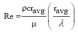 (1)
(1)
The shape of the bolus tail and a head is described using sinusoidal functions, and the main body of the bolus is approximated with a constant radius. Mathematically, it can be expressed as follows:
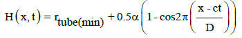 (2)
(2)
Here, á is the wave amplitude and
á = 2( ravg - rtube(min) ) (3)
These approaches can be expressed mathematically as equation to calculate the spatial and temporal variations of intraluminal pressure P(x, t) along the esophagus.
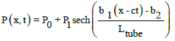 (4)
(4)
Here, b1, b2 are constants P0, P1 are constants of resting and active pressures. We chose CPGs (Central Pattern Generators) as the controller for the swallowing device because it is the control method human body [25-28]. Our research goal of the in-vitro stent performance evaluation methods includes durability testing for all type of stents, using a bend and piezo effective sensor detecting system also via the developed real time image processing system. Durability and fatigue analysis are needed because during the operation time, the material properties can change and failure due to fatigue is possible [29]. The aim of this study is to design a comprehensive testing device for stent migration and failure detection. Considering the clinical necessity, an artificial esophagus and stent with peristaltic function have been developed in this study.
Materials and Testing Methods
Materials
Arduino MEGA2560: It has 54 digital input/output pins (of which 14 can be used as PWM outputs), 16 analog inputs, 4 UARTs (hardware serial ports), a 16 MHz crystal oscillator, a USB connection, a power jack, an ICSP header, and a reset button. The operation voltage is 5v, DC current per I/O pins 40 mA, flash so flash memory is 256 KB of which 8 KB used by bootloader, SRAM is 8 KB, EEPROM is 4 KB, and working clock speed is 16 MHz.
Motor controller: High speed-422 deluxe servo motor, the motor control system is pulse with control 1500 μsec neutral, operating voltage range is 4.8v to 6.0v, operating speed 0.16 sec/60 degree, stall torque is the 4.1 kg.cm so operating angle is 45 degree/one side pulse traveling 400 μsec. Additionally, direction clock wise/pulse traveling 1500 to 1900 μsec, current drain 8 mA/idle and 150 mA/no load running, dead band width 8 μsec, weight is 45.5 g.
Stent: Alloy material: nitinol (alloy of 55% nickel and 45% titanium). This is likely due to the fact that we select a stent diameter that is adapted to the diameter of the esophagus.
Sensors: Flexi-force Pressure Sensor (FPS): Thickness 0.203 mm, Length 191 mm, optional trimmed lengths: 152 mm, 102 mm, 51 mm, Width 14 mm, Sensing Area 9.53 mm, Diameter Connector 3-pin Male Square Pin (center pin is inactive) Substrate Polyester Pin Spacing 2.54 mm. In order to measure forces above 100 lb (up to 1000 lb), apply a lower drive voltage -0.5v, -0.10v and reduce the resistance of the feedback resistor 1 kΩ min.
Repeatability is ± 2.5% of full scale, Hysteresis is 4.5 of full scale, Drift is 55 per logarithmic time scale, Response time 5 μsec. Flexible Bend Sensor (FBS): sensor structure is active length 95.25 mm, part length 112.24mm, width 6.35 mm. Mechanical specifications is life cycle > 1 million, Height ≤ 0.43 mm, Electrical specification Bend resistance range 10 kΩ to 450 kΩ, Resistance tolerance ± 30%, Power rating 0.50 Watts continuous 1 watt peak.
Experimental prototyping and testing set-up and design conceptualization
The Arduino software (IDE) makes it easy to write code and upload it to the board and directly LabVIEW interface driver using the Arduino. The Mega 2560 is a microcontroller board based on the ATmega2560. The control software is LIFA (LabVIEW Interface for Arduino) driver, through which the operation command and written in the Arduino software will be transmitted to the peristaltic motor control and a test report can be automatically generated with esophagus stent parameters, the experimental parameters and fatigue life (durability), migration test. The role of the servomotor is to generate esophageal peristaltic wave. A servomotor is a rotary actuator or liner that allows for precise control of angular or linear position, velocity, and acceleration. The position of the servo motor is set by the length of a pulse. The servo expects to receive a pulse roughly every 20 milliseconds. If that pulse is high for 1 millisecond, then the servo angle will be zero, if it is 1.5 milliseconds, then it will be at its center position and if it is 2 milliseconds it will be at 180 degrees. Using Arduino Mega2560 board to control a servo motor through an ATmega2560 microcontroller. The motors are controlled by four servo motor in variable degrees. Each motor is connected via Mega board digital output port. The control source code is written to Arduino r2 compiler and LIFA driver using the LabVIEW software. Executive Unit: Simulates the stress condition and peristaltic function of the esophagus stent in vivo. According to initial compression and creep load control signal of esophagus stent, servo motor adjusts the mega board to adapt to the esophageal stent with different size parameters. The executive unit can be divided into three parts: 1. Peristaltic part, 2. Stent part, 3.Sensor part.
Peristaltic part: To develop a functional and accurate model of the oesophagus stent migration, it is essential to understand the anatomy of the oesophagus as well as the histologic composition of the oesophageal wall as this significantly impact the swallowing physiology. By stretching and releasing the end of the wire, the peristaltic loading unit makes the coil diameter changes around the esophagus stent. The axial sequence arrangement can produce a discrete waveform in esophagus stent. The geometrical specifications, of conduit length and diameter, were inspired by measurements from the physiology of swallowing. The swallowing In-vitro testing device has been designed with an active peristaltic zone of 200 mm length and a 20 mm bore in the middle. The human esophagus is between 200-260 mm in length and with a nominal bore of 18-22 mm in the center. A mathematical model has been developed to study the peristaltic transport of a rheological for arbitrary wave shapes and tube lengths. Several wire coils can simulate the peristaltic wave effect.
Stent part: We have chosen a bare nitinol stent as an example. We have used an image processing system and stent migration detecting camera to quantify the amount of migration of the bare stent sample, we have partnered it with piezo effective sensor and bend sensor to evaluate the amount of bend force needed in determining migration failure in the sample.
Sensor part: Used LabVIEW software image processing to objectively determine the location of stent and stent migration. These sensors are preferred because of their excellent linearity and their good reactivity. The flexi-force sensor is a thin and flexible piezo resistive force sensor that is available off-the-shelf in a variety of lengths for easy proof of concept. These ultra- thin sensors are ideal for nonintrusive force and pressure measurement in a variety of application. The dynamic range of this force sensor can be modified by changing the drive voltage and adjusting the resistance of the feedback resistor. This can be used to measure of esophageal wall pressure and stent migration area. Flexible Bend Sensor is a sensor that changes its resistance depending on the amount of angle of the sensor. It converts the change in angle onto electrical resistance the higher the angle, the higher the resistance value. This can be used to the measure the esophageal constriction by determining the amount of change in angle of the flex bend sensor. The change in the resistance correlates to the diameter change of the esophageal stent. This can be used to measure of stent broken/fractured and tube peristaltic movement of testing in the signal wave. The board is power supplied to the USB port on the control computer. In Figure 1 shown the testing device general circuits. LED D1 and D2 indicated the operation condition of the device. The board is power supplied to the USB port on the control computer.

Figure 1: General circuitry schematics of the components of the non-vascular stent testing device; flex and bend sensors, Servo Motors for peristaltic movement generation, D1 LED-normal operations indicator, D2 LED –Alarm signal indicator.
The oesophagus is a complex system for robotic simulation. The schematic diagram of the test device is shown in Figure 2.

Figure 2: The schematic diagram of the non-vascular testing device operating principle.
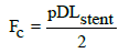
The experimental time can be adjusted by way of LabVIEW program. Execution of an immediate halt when any mistakes occur during the experiment. Moreover, alarm LED ON at the display and detecting stent migration or stent fracture. At the time, the video is uninterrupted and gives off an alarm to the user whenever a failure is detected. The experiment was done to mimic mechanical environment similar in the human body. The testing device for the actuation, control and sensing mechanisms of the esophageal simulator were presented in the force diagram of peristaltic moment in Figure 3. The force acts on the pipe structure and produces circularity tension (Fc). The pressure is perpendicular to the direction of the tube wall, which is equal to the force divided by the cavity surface area. The cyclic stress is equal to the Fc divided by the cross section area of the tube wall.

Figure 3: Photographs of the peristaltic movement generation showing the variability in diameter size of the inner silicon tube.
The cyclic stress is determined by the following equation:
 (5)
(5)
Where D is the diameter of the pipe, wt is wall thickness.
 (6)
(6)
The Fc is the circumferential load of the stent in the oesophagus. As the diameter and length of the oesophageal stent have different size in the specific range, the durability test device for oesophageal stent should simulate the peristaltic wave and can cover all the stent with different size. The Arduino LIFA drive motor mechanism was firstly used in the test to simulate the peristaltic of oesophageal stent. The regular load and peristaltic amplitude in the different body can be adjusted by stent pre-compression. The experiment was done in vivo environment as much as in the body. The tube wall attached bend sensor also inserted stent bend sensor. The nitinol stent was inserted in the tube peristaltic of the tube open and close. This moment stent tested by using bend and piezo sensors. At all times, current system activity is presented in graphical format by way of various plots and status displays. In addition, all trial-specific output may be saved to file during trial execution for archiving purposes as well as for future analysis.
Results
The oesophageal stent is revealed to rippled series of actions during swallowing. So we calculated the mean values, On average, an adult swallows about 600 times per day throughout the day including meal time, and while sleeping; thus it totals to 216,000 times in a year, and for 10 years, 2,160,000 times. Additional technical procedures are needed for the note of stent migration [30]. We used LabVIEW software to determine the location of stent and stent migration. The camera using image processing system and NI Vision assistant object tracking monitoring system as shown in Figure 4, the red square mark indicated the migration of stent and the chart field below shows the stent migration line. In addition, the metal stent has migrated to about 2 mm under continuous peristaltic movement for 2 hours. The migration monitoring was only set at the bottom of the stent because it is known that the peristaltic movement of the oesophagus can push the stent only at a downward direction.

Figure 4: Real time monitoring of the non-vascular stent migration using image processing system and NI Vision assistant.
The tube wall bend sensor signal has shown clear signals, however the stent wall bend sensor output more created more noise signal, at as it can be seen in Figure 5. The Red line represents the stent bend test starting point at 360 kΩ at 0º, Green line is for the tube bend sensor resistance at 160 kΩ at 0º, the reason why the nominal starting resistance where set at different values is due to the fact that the bend resistance value for the stent sensor has higher resistance value difference, therefore, in order to determine in real time and also not to overlap the reading of the bend sensors, we calibrated the nominal starting resistance values for both the stent and tube sensors. On the Arduino source code, an addition command was used to view the output graph separately. This is due to the structure of the stent sample, the stent is a mesh like structure and has flexible property, and therefore, creating multiple signals and skewing the signal detection of the bend sensor output normal curve values of nitinol stent compared to the tube peristaltic nominal movement.

Figure 5: Bending sensor curve of normal peristaltic movement.
Bend analysis shown in Figure 6 shows that the data acquisition was made with a 2 sec interval; this gives us 30 bending resistance values per minute. The bend sensor was set to be around the same value in measuring the resistance changes caused by bending. This was presented by the following equation:

Figure 6: Bend sensor analysis graph. (a,b) The normal bending sensor curve of tube and in a normal stent peristaltic movement. (c) For error detection, we determine in the plot as, 1160 s to 1960 s that indicates a frequency increase in the bending resistance.
 (7)
(7)
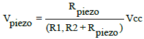
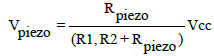
Where Vcc=5v, (R3,R4)=10 kΩ, Rbend1,2 = 10 kΩ to 450 kΩ it is variable value.
It can be seen in Figure 6 (a, b) the normal bending sensor curve of tube and in a normal stent peristaltic movement.
For error detection, we determine in the plot as seen in Figure 6c, 1160s to 1960s that indicates a frequency increase in the bending resistance. Problems such as failure in the stent cover or stent strut fracture would yield a higher bending resistance value as shown in equation f=2π(R (sensor)) C. The stent edge attached to the FPS represents the normal result. A resistance increase would determine that the part of the signal would indicate stent migration as seen in Figure 7a and as described by the equation no. 8.

Figure 7: Force sensor monitoring signals (a) Tube force sensor and Stent force sensor indicating an error signal when the resistance values increases. (b) Stent force sensor indicating an error signal when the resistance value goes over the 100 kΩ limit.
 (8)
(8)
It can be concluded that the higher the pressure value, the higher the output voltage there will be. The FPS ranges its resistance between near infinite when it is under static mode and would give out 25 kΩ when you approach its weight limit. When barely touching it, it has a resistance of around 10 MΩ. We can measure that change using one of the Arduino’s analog inputs. But to do that, we need a fixed resistor that we can use for that comparison. This is called a voltage divider and divides the 5v between the flexi-force and the resistor. It is shown in Figure 7b, that the demonstrated stent migration gives out an alert signal in the diagram. If the stent FPS resistance reaches more than 100 kΩ, then testing device will give out an alert signal to the user via the lighting of the D2 LED alarm indicator.
Discussion
There are several features and benefits for creating an in-vitro failsafe system for esophageal stenting. This can give biomedical engineers an idea on designing new stent designs on how much peristaltic force pressure is needed in determining migration on oesophageal stents. With numerous research about this topic being publish every year, it is only logical to design a system to evaluate the anti-migration properties of these medical devices. It is imperative for biomedical engineers and material scientists to create and design an effective stent in order to avoid complications of stent migrations and fractures.
The design concept of this research can give us an accelerated closed-loop servo-control of pulsatile distension, where rapid acquisition of data can be done. It also has the capability to adjust the tube length to accommodate not just one type of oesophageal stent but also colorectal and duodenal stents. A programmable control system can also be made due to the versatility of LabVIEW® software user interface and Arduino Mega® board that we have used in this study. This provides the user with real time computer control and monitoring of Image processing, Sensor data output analysis, and Alarm signal capabilities.
Conclusion
In conclusion, varied in form of stent migration and durability testing device was developed and applied for testing. In this study, we developed an esophageal stent multifunction testing device with peristaltic movement. The simulated peristaltic movement was similar to the in humans. The approved signals are digitally processed, calculating the standard distortion and establishing thresholds approved empirically. The long-term continuous test of stent sample verified the trustworthiness of the device, which could prove the smooth experiment. The newly designed device is expected to be applied to test the test of the other non-vascular stents. All sensor data outputs and top/side camera video images of the experimental device are real time recording and there is an alarm when the problem occurs. Our study, the only dry swallow was experimented to show the obligatory peristaltic wave being able to be generated and practical by LabVIEW and Arduino motor control.
References
- Aguilar LE, Tumurbaatar B, Ghavaminejad A, Park CH, Kim CS (2017) Functionalized Non-vascular Nitinol Stent via Electropolymerized Polydopamine Thin Film Coating Loaded with Bortezomib Adjunct to Hyperthermia Therapy. Scientific Reports 7: 9432.
- Gu, X, Liu L, Ni Z, Cheng J, Long Z (2013) Investigation on the Design and Experimental Application of Novel Fatigue Testing Device for Esophagus Stent. IEEE ICMA:407-411.
- Yuan T, Zheng R, Yu J, Edmonds L,Wu W, et al. (2016) Fabrication and Evaluation of Polymer-based Esophageal Stents for Benign Esophagus Stricture Insertion. RSC Advances 6: 16891-16898.
- Iwanaga A, Egashira A, Minami K, Saeki H, Yamamoto M, et al. Evaluation of esophageal and airway stent placement for patients with advanced and recurrent esophageal cancer. Esophagus 13: 283-289.
- Song J, Hu H, Jian C,Wu K, Chen X, et al. (2016) New Generation of Gold Nanoshell-Coated Esophageal Stent: Preparation and Biomedical Applications. ACS Appl. Mater. Interfaces 8: 27523-27529.
- Garbey M, Salmon R, Fikfak V, Clerc CO (2016) Esophageal stent migration: Testing few hypothesis with a simplified mathematical model. Comput Biol Med 79: 259-265.
- Aguilar LE, Nejad AG, Park CH, Kim CS (2017) On-demand drug release and hyperthermia therapy applications of thermoresponsive poly-(NIPAAm-co-HMAAm)/polyurethane core-shell nanofiber mat on non-vascular nitinol stents. Nanomedicine: NBM 13: 527-538.
- Aguilar LE, Unnithan AR, Amarjargal A, Tiwari AP, Hong ST, et al. (2015) Electrospun polyurethane/Eudragit® L100-55 composite mats for the pH dependent release of paclitaxel on duodenal stent cover application. Int J Pharm 478: 1-8.
- Sharma P, Kozarek R (2009) Role of Esophageal Stents in Benign and Malignant Diseases. Am J Gastroenterol. 105: 258-273.
- Dua KS, Latif SU, Yang JF, Fang TC, Khan A, et al. (2014) Efficacy and safety of a new fully covered self-expandable non-foreshortening metal esophageal stent. GIE 80: 577-585.
- NagarajaV, Cox MR, Eslick GD (2014) Safety and efficacy of esophageal stents preceding or during neoadjuvant chemotherapy for esophageal cancer: a systematic review and meta-analysis. J Gastrointest Oncol 5: 119-126.
- Puértolas S, Bajador E, Puértolas JA, López E, Ibarz E, et al. (2013) Study of the Behavior of a Bell-Shaped Colonic Self-Expandable NiTi Stent under Peristaltic Movements. Bio Med Research International: 10.
- Czaplik M, Antink CH, Rossaint R, Leonhardt S (2014) Application of internal electrodes to the oesophageal and tracheal tube in an animal trial: evaluation of its clinical and technical potentiality in electrical impedance tomography. J Clin Monit Comput 28: 299-308.
- León MA, Räsänen J (1996) Neural network-based detection of esophageal intubation in anesthetized patients. J CLIN MONITOR 12: 165-169.
- Dirven S, Chen F, Xu W, Bronlund JE, Allen J, et al. (2014) Design and Characterization of a Peristaltic Actuator Inspired by Esophageal Swallowing. IEEE/ASME Transactions on Mech 19: 1234-1242.
- Zhang Z, Ma J, Liu S, Liu X, Yan X, et al. (2017) Fully-covered metallic stenting in an infant with tracheoesophageal fistula due to button battery ingestion. Int J Pediatr Otorhinolaryngol 95: 80-83.
- Dirven S, Xu W, Cheng LK, Bronlund J (2014) Soft-Robotic Peristaltic Pumping Inspired by Esophageal Swallowing in Man. 2nd International Conference on Robot Intelligence Technology and Applications, Springer International Publishing: Cham, Switzerland: 473-482.
- Kim TH, Patel N, Ledgerwood-Lee M, Mittal RK (2016) Esophageal contractions in type 3 achalasia esophagus: simultaneous or peristaltic? Am J Physiol Gastrointest Liver Physiol 310: G689-G695.
- Nicosia MA, Brasseur JG, Liu JB, Miller LS (2001) Local longitudinal muscle shortening of the human esophagus from high-frequency ultrasonography. Am J Physiol Gastrointest Liver Physiol 281: G1022-G1033.
- Yu Q, Mulmi S, Liu Y (2016) The Placement of Esophageal Stents in Different Esophageal Disease Related Conditions-A Review. OJ Gas 6: 117-126.
- Banner MJ, Tams CG, Euliano NR, Stephan PJ, Leavitt TJ, et al. (2016) Real time noninvasive estimation of work of breathing using facemask leak-corrected tidal volume during noninvasive pressure support: validation study. J Clin Monit Comput 30: 285-294.
- Hsieh SW, Chen SH, Chen YT, Hung KC (2017) To characterize the incidence of airway misplacement of nasogastric tubes in anesthetized intubated patients by using a manometer technique. J Clin Monit Comput 31: 443-448.
- Patel N, Jiang Y, Mittal RK, Kim TH, Ledgerwood M, et al. (2015) Circular and longitudinal muscles shortening indicates sliding patterns during peristalsis and transient lower esophageal sphincter relaxation. Am. J Physiol Gastrointest Liver Physiol 309: G360-G367.
- Babaei A, Bhargava V, Korsapati H, Zheng WH, Mittal RK (2008) A Unique Longitudinal Muscle Contraction Pattern Associated With Transient Lower Esophageal Sphincter Relaxation. Gastroenterol 134: 1322-1331.
- Gjorgjieva J, Berni J, Evers JF, Eglen SJ (2013) Neural circuits for peristaltic wave propagation in crawling Drosophila larvae: analysis and modeling. Front Comput Neurosci 7: 24.
- Matam BR, Duncan H (2017) Technical challenges related to implementation of a formula one real time data acquisition and analysis system in a paediatric intensive care unit. J Clin Monit Comput: 1-11.
- Noh Y, Segawa M, Sato K, Wang C, Ishii H, et al. (2011) Development of a robot which can simulate swallowing of food boluses with various properties for the study of rehabilitation of swallowing disorders. ICRA: 4676-4681.
- Zhu M, Xu W, Cheng LK (2017) Esophageal Peristaltic Control of a Soft-Bodied Swallowing Robot by the Central Pattern Generator. EEE ASME Trans Mechatron 22: 91-98.
- Karagul S, Yagci MA, Ara C, Tardu A, Ertugrul I, et al. (2015) Small bowel perforation due to a migrated esophageal stent: Report of a rare case and review of the literature. Int J Surg Case Rep 11: 113-116.
- Park CH, Tijing LD, Pant HR, Kim TH, Amarjargal A, et al. (2013) Accelerated in vitro durability testing of nonvascular Nitinol stents based on the electrical potential sensing method. Appl Phys A 112: 919-926.