Spanish
  Chinese
  Russian
  German
  French
  Japanese
  Portuguese
  Hindi
Hindi Research Article, J Chem Appl Chem Eng Vol: 1 Issue: 1
Experimental Investigation of Gas-Solid Disengagement in Bubbling Fluidized Bed Cold Model
Esmail R Monazam2, Ronald W Breault1*, Ky Layfield2 and Justin Weber1
1US Department of Energy, National Energy Technology Laboratory, West Virginia, USA
2REM Engineering Services, West Virginia, USA
*Corresponding Author : Ronald W Breault
US Department of Energy, National Energy Technology Laboratory, 3610 Collins Ferry Rd, Morgantown, West Virginia 26507-0880, USA
Tel: 304-285-4486
Fax: 304-285-4403
E-mail: ronald.breault@netl.doe.gov
Received: September 07, 2017 Accepted: September 23, 2017 Published: September 30, 2017
Citation: Monazam ER, Breault RW, Layfield K, Weber J (2017) Experimental Investigation of Gas-Solid Disengagement in Bubbling Fluidized Bed Cold Model. J Chem Appl Chem Eng 1:1 doi: 10.4172/2576-3954.1000104
Abstract
The aim of this experimental study is to investigate the separation performances of a new gas-solid disengagment (GSD) device in a 10 cm bubbling fluidized bed cold model. An impactor separator is designed to be fitted internally onto the loop seal and install in the bubbling fluidized bed based on the impingement separation concept. The effects of operating parameters, such as static bed height, the length of the GSD device’s dip leg, and effect of dip leg porting were examined. The results indicated that a higher static bed height increases the mass of elutriated particles from the bed column. The length of the GSD device’s dip leg has a small effect on its separation ability. A longer dip leg can reduce the amount of particles elutriated due to the reduced pressure it experiences on the solids exit as compared to a shorter dip leg. The addition of fluidization ports to the dip leg has a negative effect on preventing particles from escaping through the gas outlet. The fluidizing gas will bypass the gas inlet of the GSD device through the dip leg and no particles will impact the baffle to be separated from the gas flow. Increasing the diameter of the solid exit for the dip leg increases the efficiency of the GSD device. The higher rate of particles passing through the dip leg reduces the chance of gas flow blockage by particles accumulating in the GSD device. The research concludes that with an effective design for a gas-solid disengagement device will reduce up to 75% of the particles that enter the filtration system that elutriate from the bubbling fluidized bed.
Keywords: Gas-solid disengagement; Bubbling fluidized bed; Combustion; Static bed height
Introduction
Bubbling fluidized bed reactors are widely used in the industry as, among others, coal combustors/gasifiers, fluid catalytic cracking (FCC), and chemical looping process [1]. However, there is considerable controversy concerning the mechanism of solids elutriation from bubbling beds [2]. In bubbling fluidized bed reactors, the heat transfer, mixing, and chemical reactions could occur mainly in the dense bed, while the freeboard usually takes up most of the bed volume in industrial process [3]. As particles are carried up the freeboard to various heights (depending on their terminal and gas velocities), they approach a height above which the fines concentration remains nearly constant and is called transport disengagement height (TDH). The height of the freeboard usually influence the elutriation rate and designed to prevent the loss of a large amount of bed material. This loss, in turn implies a higher operating cost [4]. To reduce the required height of the freeboard and the general diameter of the disengagement section of fluidized beds, Pemberton and Davidson [5] used vertical tubes as baffles above fluidized bed. They demonstrated that the freeboard baffles, in the form of a vertical bundle of tubes, reduce the TDH significantly. Callen et al. [6] using parallel inclined plates in freeboard of a gas fluidized bed to reduce the solids rate reporting to downstream cyclones and filters.
The chemical looping reactor at the Department of Energy’s (DOE) National Energy Technology Laboratory (NETL) [7,8] has experienced blockage in the filters of the loop seal and fuel reactor (Figure 1) due to an excessive quantity of particles being elutriated. Particles accumulate in the filters to the point where blockage occurs in less than 30 minutes of continuous operation. The gas distributors for both loop seal and fuel reactors are unable to evenly distribute the fluidizing gas flow due to the standpipes which pass through the distributor plates. With the standpipes passing through the distributor plates, the orifices do not have a symmetrical layout and the beds suffer for poor fluidization. To compensate, higher fluidizing gas velocities are used to ensure that entire bed is able to fluidize properly. When the higher fluidization rates are used, more particles can elutriate into the freeboard. In the case of the loop seal that has a short freeboard height it becomes a large issue because the particles do not need to travel that far to reach the gas outlet and into the filters. To prevent these materials from entering the filters, a disengagement device was design and installed to separate the solids from the gas flow. The disengagement device also needs to be fitted internally due the refractory lined walls of the reactors which present more difficulty for an external system to return elutriated particles back into the bed inventory.

Figure 1: Schematic diagram of the chemical looping combustion process.
Gas-solid separation is an issue that spreads across the process engineering industry where many technologies have been developed to remediate the problem. Concepts for gas-solid separation include; gravity and knock-out drums, centrifugal separators (cyclones), impingement separators, and filter separators. In the gravity and knock-out drums, the forces of gravity are used to separate the solid particles as gas flows through a large chamber that expands along the gas stream where the gas velocity is reduced and the residence time increased, so that the particles fall out of suspension under the influence of gravity. Within the gravity drum the gas velocity should generally be less than about 3 m/s if excessive re-entrainment of collected particles is to be avoided [9]. In the cyclones, the gas-solid stream flows in a helical path and consequently it is the centrifugal forces that divert the particles from the gas flow, where success is dependent on the gas velocity. The cyclone separates solids in the same manner as in gravity drum with the gravitational force being replaced with a centrifugal force that can vary from 50 to 1000 times the normal gravitational force [10]. The cyclone has an inlet velocity limitation due to settled solids being re-entrained from the cyclones wall [11]. Impingement separators include wire mesh and vane type separators where particles impact with obstructions to stop their momentum in the gas flow. A wire mesh separator uses a mesh screen as the obstruction that the particles must avoid while a vane type use a series of cavities along an oscillating channel that causes the particles to collide with the cavities. The filter separators use a filtration media, such as a porous metal, that small enough to only allow the gas flow to pass through. The filter separator is the most effective design however it also presents the most flow restriction which increases the pressure drop across the filter media. The biggest designs concerns for the chemical looping reactor include both size and flow restriction. Both gravity and centrifugal separators allow for low pressure operation but their size is too large to fit inside the loop seal and fuel reactors. The filtration separator allows for a compact design but it comes at the expense of flow restriction. An impingement separator satisfies both design constraints.
The approach investigated in this paper involves preventing the elutriation of particles in a bubbling bed reactor using impact separation. The benefits of an impact separation process include the lower pressure operation and the limited space required to retrofit the disengagement device into an existing unit.
Experimental
Experimental apparatus
The experimental apparatus, as shown in Figure 2, consists primarily of bubbling bed constructed with a clear acrylic pipe made of two separate sections which dimensioned 10cm in diameter and 62.2 cm in height internally. The bottom section of the bed column contained the bed and the upper section contained the GSD device, allowing for ease adjustability for both bed height and GSD device modifications. At the top of the unit, the flow would pass through the GSD device and then exit the bed column, the particles that had elutriated from the bed were captured into a micro-sized fabric filter bag attached to the gas outlet. Compressed air is used as the fluidizing gas which is controlled by a mass flow controller. A perforated plate with 25 symmetrical orifices, 1.6 mm in diameter, was used as the gas distributor. A U.S. No.325 mesh sized (44 μm) stainless steel screen was placed at the bottom of the gas distributor to prevent material in the fluidizing bed from escaping into the plenum chamber.

Figure 2: Schematic diagram for the 10-cm diameter bubbling fluidized bed
The details of the GSD device are displayed in Figure 3 emphasizing the direction of the gas flow. 1) The fluidization gas enters the GSD device with particles that have been entrained in its flow. 2) The elutriated particles then collide into the baffle where the particle’s momentum from the gas flow is abruptly reduced. The particles fall into the dip leg after the initial impact separation point. 3) The gas flow is redirected around the base of the baffle and across a 45-degree louver. Any particles that are still entrained in the gas flow must pass through a 0.3cm opening between the wall of the bed column and the edge of the 45-degree louver. After which the gas flow passes over a second 90-degree louver with the same 0.3 cm clearance between its edge and the wall of the baffle. Particles removed from the gas flow will then fall back down into the dip leg where they are fed back into the bubbling bed. Both 45 and 90 degree louvers provide additional surface area for entrained particles to collide with for impact separation. 4) Once the gas flow passes the louvers, it is redirected out of the unit through the gas outlet and into a fabric filter bag to collect the particles that were elutriated through the GSD device.

Figure 3: Gas flow between impact separation plates.
Experiments were performed by closing the air vent valve connected to an opening in the plenum chamber, thus directing the flow through the gas distributor and into the fluidized bed. The experiment would run for the allocated sampling time (30 minutes) and then the air vent valve would be opened, releasing the air flow directed to the bed into the atmosphere. The filter bag was weighed after each test run to determine the mass of the material collected, as compared to the empty bag before use. The quantities of particles entrained, E, was determined by;
 (1)
(1)
where mfinal is the mass of the collected material and filter and minitial is the mass of the clean filter.
The mass of materials collected in-between runs was recorded and then returned to the bed in order to maintain a constant bed inventory. These series of experiments were conducted under batch mode operating condition.
Experimental conditions and physical properties of test materials
Several series of experiments were conducted using 10-cm diameter bubbling fluidized bed cold model. The experimental conditions are presented in Table 1. In these experiments, 8 different GSD device design were tested using dimensionless gas velocities relative to the minimum fluidization velocity of the glass beads (Ug/Umf) at rates of 4, 6, 8 and 10 with two different static bed heights of 38, and 43 cm. Each GSD device utilized a unique combination of variable settings.
| Variable | Settings |
|---|---|
| Dip Leg Length [cm] | 30.5,45.7 |
| Elbow Size [cm] | 1.27,2.54 |
| Louvers [-] | 0,1,2 |
| Dip Leg Mesh [-] | 0,1,2 |
| Open Ports | 0,1,2 |
Table 1: Experimental variables.
The configuration of each GSD device is identified in Table 2. In the case of the number of louvers where only 1 was used it was the 90 degree louver. For the dip leg mesh, only the upper mesh was used in the case of 1 mesh screen for GSD-7.
| Design | Dip Leg Length | Elbow Size | Number of Louvers | Dip Leg Mesh | Open Ports |
|---|---|---|---|---|---|
| (cm) | (cm) | (-) | (-) | (-) | |
| GSD-1 | 45.7 | 2.54 | 0 | 0 | 0 |
| GSD-2 | 45.7 | 2.54 | 2 | 0 | 0,1,2 |
| GSD-3 | 45.7 | 2.54 | 1 | 0 | 0,1,2 |
| GSD-4 | 30.5 | 2.54 | 1 | 0 | 0,1 |
| GSD-5* | 30.5 | 1.27 | 1 | 0 | 0,1 |
| GSD-6 | 45.7 | 1.27 | 0 | 0 | 0 |
| GSD-7 | 45.7 | 2.54 | 0 | 1 | 0 |
| GSD-8 | 45.7 | 2.54 | 0 | 2 | 0 |
Table 2: Configuration of gas-solid disengagement devices.
The physical properties for bed material used for these experiments are presented below in Table 3 where the size range is identified by the maximum, average, minimum, and Sauter mean diameters (SMD), along with the particle’s characteristics of sphericity, density, and minimum fluidization velocity (Umf).
| Material | Size Range (µm) | Sphericity | Density | Umf | |||
|---|---|---|---|---|---|---|---|
| Max | Avg | Min | SMD | (-) | (kg/m3) | (m/s) | |
| Glass Beads | 226 | 183 | 152 | 182 | 0.93 | 2560 | 0.03 |
Table 3: Physical properties of tested bed material.
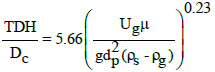
For all the experiments the calculated TDH was in the range of 0.14-0.2 m which is approximately equivalent to the freeboard height in the experiment. The TDH was calculated using the following correlation [12]:
 (2)
(2)
Results and Discussions
Figure 4 illustrates the mass of glass beads entrained from the bed as a function of Ug/Umf for two different static bed height without the GSD device (referred to as a baseline) in the bed. The data indicate that there is a nonlinear increase in the elutriating mass as a function of Ug/Umf. At low Ug/Umf, the carryover of solids from the bed is less and most of the solids are staying in the bed. With increase in Ug/Umf the carryover of solids from the bed increases, resulting in higher mass in the outlet filter. It was also observed that the elutriating mass was significantly higher at greater static bed heights. While the weight of 137 g of glass beads was elutriated in 30.5 cm bed at Ug/Umf= 8, the weight of 839 g was elutriated in 38.1 cm bed at the same Ug/Umf. At higher static bed height, the bed surface is closer to the gas exit and hence the larger fine particles become elutriable increasing the amount of entraineable solids.

Figure 4: Elutriated weight of glass bead at two different static height versus Ug/Umf without the GSD device, t=30 mins.
The performance of each of the 7 GSD device designs (Table 2) in a 38.1 cm static bed height using no dip leg porting are presented in Figure 5 as compared to the baseline (no GSD device) measurement. There were better performing designs for each Ug/Umf. used than the baseline. At Ug/Umf. = 4, there was not a discernable difference from the GSD devices’ effectiveness and the baseline measurement with less than 5 g of particles escaping the bubbling fluidized bed for all cases. When the Ug/Umf. was increased to 6, the GSD-7 design was the best performing design with 42.07 g of particles being collected. The next best devices were GSD-3 and GSD-8, collecting 62.30 g and 64.12 g, respectively. The baseline measurement being compared to was 156.76 g, therefore the device could reduce the particles elutriated from the bed by nearly 75%. Increasing Ug/Umf.= 8, the GSD-2 design performs the best by preventing nearly half of the next closest design, GSD-8. There were 838.98 g of particles collected during the baseline test run, with only 201.11 g being collected from the GSD-2 test run, resulting in a 76% decrease in particles elutriated from the bed column.

Figure 5: Effect of gas-solid disengagement design on particle entrainment static bed height = 38.1 cm, number of open dip leg ports = 0, t = 30 mins.
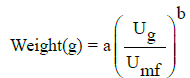
It should be noted that the experimental data were fitted to the power law (solid lines in Figure 5) with R2>99.5% as;
 (3)
(3)
The values of ‘b’ were predicted for all the experiment (except for GSD-2) to be between 5 and 6 with an average of 5.5 and the values of ‘a’ was between .0004 to .016 which depends on experimental conditions. The value of ‘b’ for GSD-2 was about 3.5. The values of b’s indicated that the elutriations of solid followed the base line (Figure 4) for all the experimental conditions, except for GSD-2. Influence of the static bed height, length of the dip leg, number of dip leg ports, elbow opening and number of louvers on solid entrainment were examined for each of the gas-solid disengagement device configurations; where results of these experiments are presented and discussed in the following sections.
Effect of static bed height
The effect of the static bed height on the entrainment of particles is presented in Figure 6. A higher static bed causes more particles to elutriate due to the reduced freeboard height. For the fixed bed column, increasing the static bed height is the same as reducing the freeboard height. Particles are not required to travel as far to reach the entrance of the GSD device which is connected to the gas outlet. If any slugging were to occur in the dip leg of the GSD device, it becomes much easier for slug to push the particles that were collected into the dip leg to be forced back through the GSD device where they would bypass the baffle and exit through the gas outlet into the fabric filter bag.

Figure 6: Effect of static bed height on particles entrained.
Effect of dip leg length
Figure 7 illustrated that the dip leg length has very little influence on the entrainment of solids. The shorter 30.5 cm dip leg has more particles being elutriated than the longer 45.7 cm dip leg for Ug/Umf. of 4 and 6, however the difference only being 3.09 g and 8.57 g of elutriated particles, respectively. The difference in dip leg length alters the location of the dip leg’s elbow where the particles that have passed through the GSD device and separated from the gas exiting the bed column are being redirected to back into the bubbling fluidized bed. A longer dip leg locates the solids exit of the dip leg closer to the base of the bed column. If segregation of the particle size distribution occurs because the smaller particles are elutriating from the bed, capturing these particles with the GSD device and returning them deeper in the bed will increase the length that the particles have to travel to become re-elutriated. By using the longer dip leg, the elutriation rate is reduced, reducing the mass of particles leaving the unit.

Figure 7: Effect of dip leg length on particle entrained.
The deeper dip leg also helps prevent gas from traveling up the dig leg, effecting the GSD separation. The fluidization gas is most uniform at the distributor plate. As the gas travels upwards through the bed, the gas will migrate towards the center and form bubbles. Therefore, if the dip leg is in the center, the higher the exit of the dip leg is in the bed, the more gas will enter the dip leg disrupting the flow of solids down the standpipe. This is more evident comparing the number of ports in the following section.
Effect of dip leg porting
To examine the effects of fluidizing the particles that had collected into the dip leg of the GSD device, two orifices, 2.54 cm in diameter, were drilled along the length of the dip leg. These orifices or “ports” would allow for the fluidizing gas from the distributor to enter the dip leg and partial fluidize the materials that had been collected in the dip leg in hopes to increase the rate at which the particles would be fed back into the bubbling bed. The experiments were performed by covering the port(s) with tape to prevent the fluidizing gas from entering the dip leg. The results showing the effect of the dip leg porting are presented in Figure 8 where the more ports that were open on the dip leg, the more particles were elutriated from the bed. During the experiments with the ports open, it became evident that the gas entering the dip leg was causing the particles to fluidize violently to the point where they would be elutriated back up into the GSD device where they would bypass the baffle and were able to exit the bed column through the gas outlet. Depending on the length of the dip leg, slugging would occur inside the dip leg for the higher fluidizing gas velocities where large amounts of particles would be forced through the GSD device and out the gas exit into the fabric filter bag. The fluidizing gas from the distributor would enter the dip leg due to the lower pressure between the material in the dip leg and the bubbling bed itself. There was less resistance for the gas to pass through the dip leg and reach the gas exit than there was for it to pass through the bubbling bed and into the gas entrance of the GSD device.

Figure 8: Effect of dip leg porting on entrainment GSD-3, static bed height = 38.1 cm, t = 30 min.
Effect of dip leg elbow size
To determine the effect of GSD device’s dip leg elbow size on the particles being elutriated, two different elbow diameters of 1.25 and 2.5 cm were used. The results displayed in Figure 9 indicate that the larger diameter elbow was the preferred choice. Inversely to the effect of porting, the larger diameter elbow did not allow more fluidizing gas to enter the dip leg and cause the particles to elutriate or slugging to occur. When the elbow diameter was reduced to the smaller size it restricted the flow of the particles from the solids exit of the dip leg. The particles could not move freely and accumulated a higher rate inside the dip leg than they were exiting. The dip leg’s bed height grew to the point where the bed’s surface was immediately below the baffle of the GSD device, creating a smaller channel for the gas flow. The gas flowing through this channel increased in velocity to where the particles that impacted with the baffle would not separate from the gas flow and were carried through the gas outlet of the GSD device and into the filter.

Figure 9: Effect of dip leg elbow size on particle entrainment.
Effect of louvers
The effect of louvers on the entrainment is shown in Figure 10 where the more louvers used allowed for better separation of the solids from the gas. The louvers provided additional surface area for impact separation to occur. Not only would the elutriated particles impact the baffle at the entrance of the GSD device but any that were not initially separated from the gas flow also impacted with the louvers before reaching the gas flow exit. The addition of louvers created a smaller diameter channel for the gas flow exiting, thus increasing its velocity. Any particles that remained in the gas flow after the impact with the baffle were then accelerated as the gas flow neared the gas exit and impacted with the louvers with enough force to reduce their momentum and fall into the dip leg of the GSD device where they would be returned to the bubbling bed.

Figure 10: Effect of louvers on particle entrainment.
Effect of dip leg mesh
The addition of mesh screen inside the dip leg of the GSD device was examined to understand the effects it would have on dispersing gas flow. The results of applying mesh screen inside the dip leg is presented in Figure 11 where it is observed that there is an influence on particles being elutriated. During operation at high fluidizing gas velocities, gas could be directed inadvertently into the dip leg, where gas bubbles could form. As the gas bubbles traveled up the dip leg, they would burst at the surface of the bed and eject particles towards the gas outlet. With the addition of mesh screens that were sized large enough for the 185μm glass bead particles to pass through freely, it would cause the gas bubbles to also pass through the mesh screen and disperse the gas flow, thus reducing their ability disrupt the particles at the surface of the dip leg. The results show that the use of both upper and lower mesh was the most effective at the highest gas velocity of Ug/Umf. = 8, while only the use of the upper screen performed slightly better at Ug/Umf. = 6. In all cases, the use of mesh aided in the reduction of particles elutriated.

Figure 11: Effect of dip leg mesh on particle entrainment.
Summary
Several experiments were conducted in a 10 cm diameter bubbling fluidized bed cold model. Results of these experiments can be summarized as follows. (1) The static bed height of the bed influences the particles that are elutriated from the bed column. A higher static bed height increases the mass of particles that elutriate. (2) The length of the GSD device’s dip leg has a small effect on its separation ability. A longer dip leg can reduce the mass of particles elutriated due to the reduced pressure it experiences on the solids exit as compared to a shorter dip leg. The larger pressure imbalance between the pressure drop across the height of the dip leg and the pressure drop across the bed at the height of the solids exit allows for a higher rate of particles to pass through the dip leg. (3) The addition of fluidization ports to the dip leg has a negative effect on preventing particles from escaping through the gas outlet. The fluidizing gas will bypass the gas inlet of the GSD device through the dip leg and no particles will impact the baffle to be separated from the gas flow. (4) Increasing the diameter of the solid exit for the dip leg increases the efficiency of the GSD device. The higher rate of particles passing through the dip leg reduces the chance of gas flow blockage by particles accumulating in the GSD device. (5) Adding louvers provides more surface area for impact separation of the elutriated particles to occur. Particles impacting surfaces impede their momentum and cause them to separate from the gas flow. (6) The addition of mesh screen reduces the mass of particles that are elutriated by dispersing any bubbles or slugs formed from the gas flow that enters the dip leg of the GSD device. The results of research conclude that the gas-solid disengagement device developed allows for effective separation of the solid particles from the gas flow. An optimize design can be created based the configuration of the device. Future experiments will investigate other design features such as louver characteristics and dip leg geometries.
Disclaimer
The authors declare no competing financial interest. The U.S. Department of Energy, NETL, and REM contributions to this paper were prepared as an account of work sponsored by an agency of the United States Government. Neither the United States Government nor any agency thereof, nor any of their employees, makes any warranty, express or implied, or assumes any legal liability or responsibility for the accuracy, completeness, or usefulness of any information, apparatus, product, or process disclosed, or represents that its use would not infringe privately owned rights. Reference herein to any specific commercial product, process, or service by trade name, trademark, manufacturer, or otherwise does not necessarily constitute or imply its endorsement, recommendation, or favoring by the United States Government or any agency thereof. The views and opinions of authors expressed herein do not necessarily state or reflect those of the United States Government or any agency thereof.
Acknowledgment
The authors acknowledge the Department of Energy for funding the research through the office of Fossil Energy’s Gasification Technology and Advanced Research funding programs. Special thanks go to Douglas Straub, and Joseph S. Mei for their assistance with experimental work and data.
References
- Yang W-C (2003) Handbook of fluidization and fluid–particle systems. Marcel Dekker, New York.
- Chew JW, Cahyadi A, Hrenya CM, Karr R, Cocco RA (2015) Review of entrainment correlations in gas–solid fluidization. Chem Eng J 260: 152-171.
- Almendros-IbáÅ„eza JA, Sánchez-Delgado S, Sobrino C, Santana D (2009) Experimental observations on the different mechanisms for solid ejection in gas-fluidized beds. Chem Eng Process 48: 734-744.
- Tardin PR Jr, Goldstein L Jr, Bizzo WA (2015) Entrainment of FCC particles from a pilot scale bubbling fluidized bed. Part 2: A mechanistic model, Powder Tech 269: 605-616.
- Pemberton ST, Davidson JF (1986) Elutriation from fluidized beds-II. Disengagement of particles from gas in the freeboard. Chem Eng Sci 41: 253-262.
- Callen A, Moghtaderi B, Galvin KP (2007) Use of parallel inclined plates to control elutriation from a gas fluidized bed. Chem Eng Sci 62: 356-370.
- Weber J, Straub D, Bayham S, Breault RW (2016) Operating experience of a 50-kW methane chemical looping reactor. Fluidization XV, Montebello, QC, Canada.
- Bayham S, Weber J, Straub D, Breault R (2017) Performance of a raw hematite and a manufactured copper-iron oxygen carrier in a 50-kW natural gas chemical looping system. 12th International Conference on Fluidized Bed Technology, Krakow, Poland, 917-924.
- Wiencke B (2011) Fundamental principles for sizing and design of gravity separators for industrial refrigeration. Int J Refrig 34: 2092-2108.
- Wei J, Zhang H, Wang Y, Wen ZI, Yao B, et al. (2017) The gas-solid flow characteristics of cyclones. Powder Tech 308: 178-192.
- Basu P, Fraser SA (1991) Circulating fluidized bed boilers: design and operations. Butterworth Heinemann, Oxford, United Kingdom.
- Ko CK (2012) Hydrodynamics in Bubbling and Circulating Fluidized Beds and Cyclone Performance of Iron Ore Particles. Korea Advanced Institute of Science and Technology, KAIST, Seoul, Korea.