Research Article, J Pharm Drug Deliv Res Vol: 12 Issue: 2
G-Reactor to Pharmaceutical Productions
Jorge Abreu Menendez*
Department of Pharmaceutical, Technologic University of the Habana, Habana, Cuba
*Corresponding Author: Jorge Abreu Menendez
Department of Pharmaceutical, Technologic University of the Habana, Habana, Cuba
E-mail: Jorge.abreu164@gmail.com
Received date: 13 September, 2022, Manuscript No. JPDDR-22-74483;
Editor assigned date: 16 September, 2022, PreQC No. JPDDR-22-74483 (PQ);
Reviewed date: 30 September, 2022, QC No. JPDDR-22-74483;
Revised date: 24 February, 2023, Manuscript No. JPDDR-22-74483 (R);
Published date: 06 March, 2023, DOI: 10.4172/2325-9604.1000209
Citation: Menendez JA (2023) G-Reactor to Pharmaceutical Productions. J Pharm Drug Deliv Res 12:2.
Abstract
G-reactor constitutes an innovation to small pharmaceutical productions and unit operations of the chemical industry at micro-plants, cap: 2.5-3.5 cubic meters and the processes in batch, vliq: 100-150 liters approximately. G-reactor distinguishes by pneumatic driving mechanism to power input and standard impeller system to the mixing operations involving Newtonian fluids and mass-transfer; a simple low-cost design warrants the reactor sealing without risks to the human health by pathogens; mechanical breaking of unwanted foams and simple practices on samplings and supplies improve the reactor performance; usual transfer rates at gas liquid systems are foreseen; a single compression unit provides the sterile air to the power supply and the oxygen of biochemical processes at micro-plants; the software enables the search and calculus of parameters involved at the reactor operation to specific process conditions; the main estimated values at technical specifications is shown; a brief technical description of integral compression units at micro plants may introduce the readers to the process engineering and the preliminary analysis of costs; the treatment of the residual gas flow is proposed.
Keywords: Pharmaceuticals; Mass transfer; Bioreactors; Mixing; Vaccines; Antibiotics; Stirrer reactors; Gas liquid
Introduction
Gas liquid systems are present to a number of industrial applications; a common application involves the mass transfer of a sparingly soluble gas into a liquid where a reaction may occur, for example the fermentation under aerobic conditions to the production of antibiotics, steroids and single cell proteins; the mixing operation to improve the homogenization, mass transfer and heat takes part at this goal of biochemical reactors; other productions such as vaccines and biological drugs is accomplished to stirrer reactors and the processes in batch at present. The challenges on design and construction of biochemical reactors are known, among them the process asepsis and isolation, flow patterns and shear stress, measure and control, mass transfer, samplings and supplies, materials, valves and fittings, power consumption, the scale up and the process economy, etc. other considerations about the reactor productivity and yield, product purification, water management, energy requirement and waste treatment must be regarded on design time. New reactor designs should be capable of reliable operation and control enough to providing an overall plant optimization over a reasonable range of process fluctuations.
Materials and Methods
Technical features
G-reactor allows between parameters at controls, the air flow rates to power input and the oxygen transfer at proper aeration rates for cellular growth and respiration.
G-reactor distinguishes by simple pneumatic device of variable speed per substitution of common driving mechanisms to analogous reactors, namely the induction electric motors, the structural support of the impeller shaft in cantilever, the aseptic mechanical seal and magnetic couplings indistinctly.
G-reactor is intended for aseptic biochemical processes of biological risks by pathogens; strict isolation and trouble free operations are ensured by a simple low cost design; simple technological practices on samplings and supplies and mechanical break of unwanted foams distinguishes the reactor design [1].
Higher mass transfer rates to aerobic biochemical processes under gauge pressure control is foreseen in agreement with the two film theory namely the higher transfer rates to incremented values of gas partial pressures into the liquid phase are expected to improve the cellular growth and respiration with significant repercussion on yields, the process economy, etc. To this aim the automatic process control or an estimated gauge pressure value may be assumed to biochemical applications [2]. Common transfer rates values may be found between 18 mmol/lit.hr and 225 mmol/lit.hr respectively (to atmospheric pressure and air) and growth rates only up to 7 g/lit.hr-8 g/lit.hr; higher transfer rates are obtained only by unreasonably high power inputs or the use of higher pressures and/or pure oxygen [3]. A single small capacity compression unit provides the sterile air to power input and the oxygen of biochemical processes in micro plants; the reactor operation is simple, the impeller speed and the aeration rate to biological systems are set respectively by automatic control valves [4,5].
G-reactor supports standard impellers on single and multi-impeller systems, the standard turbine impeller to mass transfer and the mixing operations involving low viscosity fluids and Newtonian behavior.
G-reactor constitutes a low cost alternative to aerobic biochemical applications at micro plants for small productions and common unit operations of the chemical industry; previous jobs develops the calculus fundamentals and the software that support the reactor’s design and the technical feasibilities. This job may be useful to references at pre-grade and it may set the bases to new developments and researches.
Description and operation
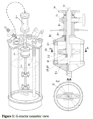
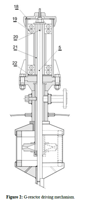
G-reactor equipped by multi-impeller systems, four flat paddle turbine impeller and single baffle vessel is represented to the isometric view for illustration; the driving mechanism is shown at cross-section. G-reactor is made up basically by short tube sections and three main elements to descriptions, i.e., the driving mechanism, the pneumatic device and the mixing impeller. The driving mechanism constituted by the tandem of ball bearings and the steel bar or tube should withstand the hydraulic forces and the heat expansion to sterilizations by direct steam flow, preventing oil contaminations to the biological system by compression gaskets the short tube section at changeable bearing housing is constrained to rotational motion by the wedge. The inner parts of the pneumatic device are made from inert sintering compounds and clad steel; the set of bend paddles are placed on both wall fitting groove elements by hydraulic press; the whole system is resting over the screwing steel flange and the air feed tube ending closed by the screwing cap and the sliding bearing; the steel part keeps both screwing laval nozzles at the air jet to power input; the screw bolt enables the unit assembling at the extreme maintenance periods to replace wear nozzles and rolling bearings; the pneumatic device has two possible air outlets to the reactor chamber, i.e., the small holes at welding caps and the clearness of the sliding bearing at the occlusion; the gas expands to the reactor chamber and specific conditions of temperature and gauge pressure and before release to the atmosphere is subject to prophylaxis; a relief valve may assume the gauge pressure control to the exhaust gas avoiding possible drag of fluids by simple constructive solutions. Optionally, direct speed readings may be taken from the steel bar and flexible connection to the speed meter or electromechanical transducers (Figure 1).
The reactor asepsis at process runs depend on the manufacture standards and technological practices, etc. The sterilization procedures to immersions and flowing flows, the air quality and supplies and the sanitary surfaces is essential as usual; to our concern, the G-reactor deals with some facts by own design, i.e., the pneumatic device to positive working pressures should behave as sterilization impurities trap and one way unit (no-return) to continuous air flowing avoiding unwanted interchanges and reducing the contamination risks. G-reactor takes advantages from the available sterile air at micro plants; the outlet temperature at single stage and adiabatic compressors to the operating pressure of 3 kg/cm2 gauge rises above 150°C and 220°C at the inlet air temperatures of 20°C and 70°C respectively. Safe technological practices improve the reactor performance, i.e., the extraction of liquid samples from a thin tube at the liquid bulk to positive pressure head, the supplies at suspensions on the air stream by simple venturi systems and mechanical break of unwanted foams avoiding chemicals. The reactor speed is fitted by gas flow control and needle valves usually and to over loadings the pneumatic device stops functioning with no further damages (Figure 2).
Legend
1. Driving mechanism, 2. Pneumatic device, 3. Turbine impeller, 4. Gas-outlet, 5. Impeller shaft, 6. Flange, 7. Assembling screw bolt, 8. Air feed-tube, 9. Sliding bearing, 10. Upper cap, 11. Vanes holder, 12. Curved blades, 13. Laval nozzle, 14. Nozzle holder, 15. Screwing cap, 16. Sliding bearing, 17. Air outlet, 18. Compression gasket, 19. Ball bearing, 20. Wedge, 21. Bearing holder, 22. Compression gasket
Power-input
An admissible air jet to the reactor chamber is assumed to practical experience and single tube with three outlet orifices over the liquid surface in five liters vessel (3 mm diameter; 120° each); a rough value, Qtot=20 m3/hr. (N) is measured and accepted to the experience at references of this job and maximum flow rate to power input, consequently G-reactor becomes constrained to maximum power rates, Pow/Vliq=0.015 W/lit-0.340 W/lit., approximately in compliance with the software calculations and the strong mild agitation regime accepted (Table 1) in agreement with the power requirements at gas liquid systems for a complete and rapid gas dispersion [5]; common transfer rates to aerobic fermentations are ensured to power inputs, 0.098 W/lit-0.493 W/lit, approximately [6]. A singularity arises between the mixing impellers, i.e., a significant reduction at power requirements to immersed impellers at gassed systems takes place (fg=Pg/Pow=0.3-1.0) and G-reactor may improve the technical performance considerably by virtual power increments around the seventy percent (1.70 Pow) [7].
| Agitation level | HP/lit (up to) | W/lit (up to) |
|---|---|---|
| Weak | 1.26 × 10⁻⁴ | 0.095 |
| Mild | 2.34 × 10⁻⁴ | 0.191 |
| Strong | 6.44 × 10⁻⁴ | 0.485 |
| Very strong | >1.26 × 10⁻⁴ | >0.485 |
Table 1: Agitation level of stirrer tanks (only to references).
Design example
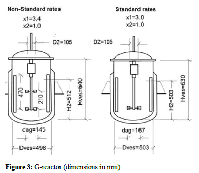
The maximum power rate at the scale up is found to a specific process of liquid volume, Vliq=100 lit. (Vves=1.25 Vliq, non-standard vessel at geometrical rates, x1=3.4, x2=1.0; six-flat-blade turbine impeller, four baffles each, 0.1 Dves); the mix liquid properties are refereed to newtonian fluids, i.e., the density, ρliq=1200 kg/m3 and viscosity, μ=0.0012 kg/ms, (1.2 cp) the air-pressure and temperature, P1=4.20 kg/cm2, T1=300 K; pressure-head (reactor chamber), P2=1.50 kg/cm2; laval-nozzle diameter, do=2.50 mm; number of bend paddles, Np=20; pneumatic device diameter, D2=105 mm (4 in.); energy loss factors, k1=k2=0.75; the aeration rate to the culture broth, Qg=20 lit./min (N) (0.2 vvm) [8].
Results and Discussion
G-reactor is constrained to maximum air flow rate to the power input, Qtot=20 m3/hr (N), consequently the maximum reactor scale is found at trial and error and the set maximum value; the software enables comparative results about the reactor performance on systems of geometric and dynamic similitude at design time; among the search variables the power rates to reactor regimen of strong mild agitation; a summary of the main variables show rational and non-contradictory values at the overall energy loss-factor, k=0.60 on the author opinion (k1=k2=0.75) (Table 2). The scheme of G-reactor at data example is shown in Figure 3.
| Broth data-example | Water | ||
|---|---|---|---|
| Un-gassed | Gassed (0.2 vvm) | Un-gassed | |
| Air pressure, P1 (kg/cm2) | 4.20 (4.34) | 3.30 (3.40) | 3.71 (4.42) |
| Air-flow, Q (m3/hr)(N) | 19.8 (20.4) | 15.6 (15.9) | 17.5 (20.8) |
| Impeller speed, n (rpm) | 200 (180) | 200 (180) | 200 (200) |
| Power input, pow (W) | 28 (26.7) | 19.9 (18,7) | 23.7 (30.6) |
| Consumption, cpow (kW) | 0.98 (1.05) | 0.62 (0.65) | 0.7 (1.08) |
| Power rate, pow/vliq (W/lit) | 0.29 (0.27) | 0.20 (0.19) | 0.2 (0.31) |
| Reynolds, re (-) | 71540 (84370) | 71540 (84370 ) | 59617 (78120) |
| G-reactor of standard geometry (Vliq=100 lit; Vves=1.25 Vliq; x1=3.0; x2=1.0) in parenthesis | |||
Table 2: G-reactor, technical specifications, vliq=100 lit (Vves=1.25 Vliq; x1=3.4; x2=1.0).
Reiterative calculations to strong influence factors at power input leads to the maximum reactor scale Vliq=100-150 lit. (Vves=1.25 Vliq) and the general conclusions; among factors of strong influences and the accepted maximum values at calculations, the reference diameter, Dref=0.090 m; the pneumatic device diameter, D2=0.105 m (4.0 in) and the number of bend-paddles, np=20, etc, however G-reactor may improve the consumption parameters considerably of Table 1, i.e. a significant reduction around the sixty percent, 60% is estimated to rational increments of diameter from, D2=4.0-5.0 inches approximately and not less significant at common reactor regimens of mild agitation; (n<180 rpm); worthy of mention the slow large and fast-small impellers may show similar power rates to proper operation speeds, however the reactor performance may result quite different to facts and evidences at the scale up, the process response and the investment, etc [9].
Micro plants
G-reactor constitutes a low-cost alternative at micro plants for small productions; a single compression unit provides the sterile air to the power supply and the oxygen of biochemical processes, however the air at the compression keeps the capacity of absorption and retention of water at vapor stage and should be refrigerated and dried to the integral compression units in order to eliminate condensates; about the air-quality and parameters for regulation and control, the air pressure and temperature, wet content, microbial population, rare particles on suspensions, etc. A brief description of integral compression units is shown.
Alternative compressors
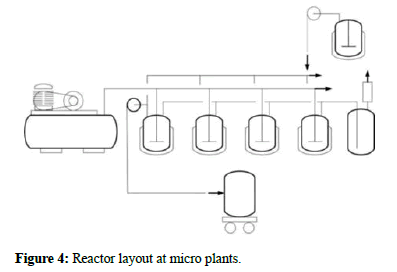
The alternative compressors show important advantages to the use, maintenance and sale offers, becoming the best choice to the industry and services frequently; the air to oil free alternative compressors is certificated for the pharmaceutical industry, foods, chemistry and labs, etc. Technical specifications of air compressors show outlet temperatures of 130°C and 80°C to alternative and rotary compressors and water contents depending on the temperature and pressure. The scheme illustrates micro plants powered by a single compression unit. (Figure 4). The oil-free alternative compressors and the following technical specifications are recommended. (1 bar=1.02 kg/cm2).
Single-stroke, single-stage, air cooling; capacity-range up to 1.0 m3/min. (N), 8 bar.
Single-stroke, two-stage, air cooling; capacity-range from 1-10 m3/min. (N), 8 bar.
Cooler-separator
The air-refrigeration takes place from 130°C up to 30°C-35°C approximately to arrangements of tubes usually of copper and water cooling on heat exchangers, eliminating approximately the 80% of condensates by siphon; the heat transfer by forced convention induced by fans may be employed to certain conditions and small compression units, whereas to multi stage compressors (two or more), the refrigeration takes place between compression stages and similar systems integrated to the compression unit itself. The air still containing water at cooler separators must condense while decreasing the temperature and it is eliminated completely on the drying systems [10].
Drying system
Two systems are described briefly, those using absorbent materials such as the alumina and the frigorific systems respectively; dew points up to -20°C may be reached to the absorption methods where later condensations at practical conditions should not occur; the air refrigeration to frigorific systems takes place up to 3°C and further heating to the service pressure from the yield heat at previous refrigeration process, showing low costs and simple maintenances, for example the typical commercial Freon based refrigerated compressed air dryer.
Distribution tanks
The air compressors works at cyclic operation regime to distribution tanks, otherwise the air compressors should work continuously. The air pulsations are reduced in the distribution tank which should satisfy the air supply on the resting times; the distribution tanks at service pressure should overcome the pressure losses of the entire installation, namely the drying system, the final air treatment for biological processes and the distribution lines, etc. According to installation sizes and reactor layouts in micro plants, common pressure loss values may oscillate from 0.2-0.4 bar. (Useful to designing installations of compressed air at micro plants).
Prophylaxis
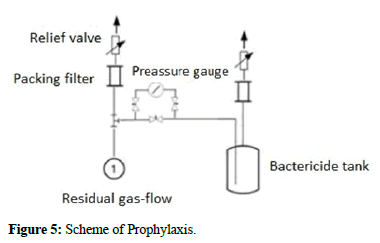
The prophylaxis treatment of the residual gas flow to positive pressure is proposed by continuous gas sparging into bactericides in order to kill harmful microorganisms on suspensions; the dimensions of agitation tanks at gas sparging via perforated tubes may be known. The scheme illustrates the method (Figure 5).
Micro-plants may show the next technical specifications
• 25 reactors, Vliq=100 lit-150 lit.
• 2.5-3.5 cubic meters.
• Single compression unit, Capacity: 1-10 m/min, 8.0 bar (abs).
• P1=3.40 kg/cm.
• Qtot=8.35 m/min (N).
• 27 kW/hr.
Nomenclature
• Energy Consumption (kW).
• Impeller diameter (m).
• Vessel Diameter (m).
• Reference Diameter (m).
• Pneumatic device, external diameter (m).
• Power rate at gassed systems (-).
• Liquid height (m).
• Vessel height (m).
• Adiabatic constant, air k=1.4 (-).
• Friction loss factor in nozzles (percent).
• Air jet, impact loss factor (percent).
• Number of impellers (-).
• Rotational speed (rps).
• Pneumatic device, number of vanes (-).
• Gassed systems, power consumption (W).
• Nozzle inlet, working air-pressure (Pa).
• Nozzle, critical pressure (Pa).
• Reactor chamber, gauge-pressure (Pa).
• Power input (W).
• Actual gas flow (m/min).
• Aeration flowrate (N) (1.033 kg/cm, 0C).
• Mass flowrate (kg/s).
• Total gas flow rate (m/hr.) (N).
• Air constant, R=287(N. m/kg. K).
• Reynolds number (-).
• nozzle, inlet air temperature (K).
• Vessel volume (m).
• Liquid volume (m).
• x1=Dves/dag, vessel geometrical rate (-).
• x2=H2/Dves, vessel geometrical rates (-).
Greek letters
• Kinematics viscosity (kg/m. s).
• ρair air-density, (1.29 kg/m) (1.033 kg/cm-0C).
• Mix-liquid density (kg/m).
• Specific weight (kg/m).
Conclusion
In compliance with the calculus fundamentals and concepts and the practical purposes of this job, the author arrives to the next conclusions. G-reactor may support standard impellers on single and multi-impeller systems, the standard turbine impeller to mass transfer and the mixing operations involving low viscosity fluids and Newtonian behavior; the new reactor should be submitted to the standards and certifications of pressure vessels and the process validations. G-reactor constitutes a low cost alternative to aerobic biochemical applications and unit operations of the chemical industry at micro plants, cap: 2.5-3.5 cubic meters and the processes in batch, Vliq: 100 liters 150 liters approximately. G-reactor distinguishes by simple low-cost driving mechanism of variable speed and maximum flow rate to power input by own design, Qtot=20 m3/hr (N).
G-reactor, Vliq=100 lit. (Vves=1.25 Vliq, D2=4.0 inches, standard geometry (x1=3.0, x2=1.0); single turbine impeller, six flat-blades, four baffles each, 0.1 Dves) show the following technical specifications to aerobic biochemical applications (gas-liquid systems) and the mix-liquid properties to references of Newtonian fluids (density, ρliq=1200 kg/m3; viscosity, μ=0.0012 kg/m.s,1.2 cp); airpressure, P1=3.40 kg/cm2; pressure-head (reactor-chamber), P2=1.50 kg/cm2; air-consumption, Qtot=15.9 m3/hr (N); power-rate, Pow/ Vliq=0.19 W/lit; impeller speed, n=0-180 rpm; the energy, Cpow=1.05 kW; a significant reduction around the sixty percent, 60% is estimated to rational diameter increments from, D2=4.0-5.0 inches at Figure 1 and not less significant at common reactor regimens of mild agitation. (n<180 rpm).
G-reactor show simple safe practices on samplings and supplies and mechanical break of unwanted foams by own design; common sterilization procedures by immersion and flowing flows may apply.
References
- Abreu J (2016) Gassed Biochemical Reactor. Natl Inst Scifi Res 47:1-5. [Google Scholar]
- Abreu J. Gassed biochemical reactor. Spanish ed, Editorial Academica Espanola. Madrid, Spain 2017. 1-57.
- Abreu J. Gassed bioreactor. Virtual pro magazine, process simulation. Colombia 2021. 1-237.
- Aiba S, Humphrey AE (1973) Biochemical engineering. Aiche J 20:1-834. [Crossref] [Google Scholar]
- Charles M. Challenges for bioreactor design and operation. Wiley-VCH Verlag GmbH and Co. KGaA. Lehigh University, USA 1975. 1-34. [Crossref] [Google Scholar]
- Hicks W, Gates EL (1976) How to select turbine impellers for dispersing gas into liquids. Chem Eng 7:141-148. [Google Scholar]
- Ocon J, Vian A. Elements of chemical engineering. Prentice Hall. New Jersey, U.S. 1986. 361-365. [Google Scholar]
- Rushton JH, Costich EW, Everret HJ (1950) Power characteristics of mixing impellers part 1. Chem Eng Prog 46:395-476. [Google Scholar]
- Vega G, Quintanilla A, Belmonte M, Casas JA (2022) Kinetic study of phenol hydroxylation by H2O2 in 3D Fe/SiC honeycomb monolithic reactors: Enabling the sustainable production of dihydroxybenzenes. J Chem Eng 428:131128. [Crossref] [Google Scholar]
- Li M, White G, Wilkinson D, Roberts KJ (2005) Scale up study of retreat curve impeller stirred tanks using LDA measurements and CFD simulation. J Chem Eng 108:81-90. [Crossref] [Google Scholar]
 Spanish
  Chinese
  Russian
  German
  French
  Japanese
  Portuguese
  Hindi
Hindi 