Research Article, J Comput Eng Inf Technol Vol: 12 Issue: 6
Measurement Accuracy of 3D Reconstruction for Small Objects
Indrit Enesi* and Anduel Kuqi
Department of Electronic and Telecommunication, Polytechnic University of Tirana, Tirana, Albania
*Corresponding Author: Indrit Enesi
Department of Electronic and
Telecommunication, Polytechnic University of Tirana, Tirana, Albania
E-mail: ienesi@fti.edu.al
Received date: 19 October, 2022, Manuscript No. JCEIT-22-77787; Editor assigned date: 24 October, 2022, PreQC No. JCEIT-22-77787 (PQ); Reviewed date: 07 November, 2022, QC No. JCEIT-22-77787; Revised date: 03 February, 2023, Manuscript No. JCEIT-22-77787 (R); Published date: 10 February, 2023, DOI: 10.4172/2324-9307.1000259
Citation: Enesi I, Kuqi A (2023) Measurement Accuracy of 3D Reconstruction for Small Objects. J Comput Eng Inf Technol 12:2
Abstract
3D reconstructions are widely used, the main challenge of them is the accuracy especially for small and detailed objects. Various software exists for 3D reconstruction, free and paid ones with various performances. In this paper the performance of 3D object reconstruction will be evaluated in terms of size accuracy. The aim of the paper is analyzing the size accuracy of the reconstructed 3D models based on photogrammetry for small objects. Meshroom is used for 3D photogrammetry reconstruction and various software is used for measurement. Blender, meshmixer and blender and 3D slicer are used for measurement, all are free software. Experimental results show a high accuracy for objects sizes measured using meshmixer.
Keywords: Photogrammetry; 3D reconstruction; Meshroom; MeshLab; Meshmixer; Blender; 3D slicer; Size accuracy; Small objects
Introduction
Undoubtedly that the uses of 3D computer vision are growing at an extraordinary rate in different fields of industry, among which we can mention 3D printing, archeology and medical, etc. As the fields for 3D application possibilities are constantly increasing, so are the various solutions for providing these technologies. The aim of the paper consists in the study of software that provides 3D reconstruction from images taken with usual camera, a mobile phone camera or a professional one. The software used for 3D reconstruction based on photogrammetry is meshroom [1]. It is free, open-source 3D reconstruction software based on the Alice vision framework [2]. Alice vision is a photogrammetric computer vision framework which provides 3D reconstruction and camera tracking algorithms [3]. Meshroom is designed as a nodal engine [4]. This is a very special feature of meshroom because the parameters can be changed very easily. It allows adding other nodes besides those provided by default and the parameters for the added nodes can be modified easily. Meshroom is developed in Python while the Alice vision framework is developed in C++ [5]. It is as a very good place for 3D reconstruction based on photogrammetry, for analysis and for measurements [6], widely used by researchers.
The dimensions of the object reconstructed in meshroom are determined to compare the measured values of the target object with the real ones. For measurement four different software will be used, meshlab, meshmixer, blender and 3D slicer. Based on the comparison, the optimal solution will be concluded.
Section two describes the methodology used in the paper, section three describes the experimental part and its analysis of results, concluding with the conclusions of the paper.
Materials and Methods
Photogrammetry
Photogrammetry is a technique that enables the creation of 3D models from photos taken from real objects in different positions, possibly keeping the object static [7]. It works by extracting 2D data and superimposing them. Since objects are of different sizes, photogrammetry is used in various fields and applications such as topographic maps or points clouds [8]. The process of obtaining 3D models would be much more complex if we did not use modern software today.
For this article the software we will use are meshroom, meshlab, meshmixer, blender and 3D slicer.
Meshroom software
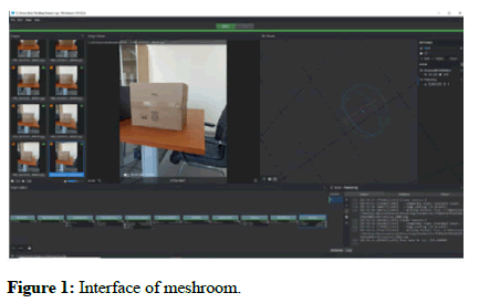
The photo inputs are placed below the left top part, the right top part serves to display the output of the photo processing (more specifically it serves to display the final output, the 3D object created but here can also be displayed the result of special nodes when executed). The bottom part is undoubtedly the most important part, more specifically in the left bottom part is given the graph editor which shows the nodes that participate in the execution workflow. As we mentioned, the nodal environment makes meshroom software very special because each node is performed individually. While the bottom right section shows the characteristics for each particular node, more specifically the outputs, statistics and status are displayed as shown in Figure 1. The photos were taken through usual cameras. The individual tasks are represented by nodes combined into directed acyclic dependency graphs that are named pipelines [9].
In this paper the default nodes will be used, camera initialization, feature extraction, image matching, feature matching, structure from motion, depth map, depth map filter, meshing, mesh filtering and texturing.
CameraInit loads image metadata, sensor information and generates viewpoints, sfmcameraInit.sfm. Feature extraction extracts features from the images as well as descriptors for those features [10]. Image matching is a processing step which figures out which images make sense to match each other. Feature matching finds the correspondences between the images using feature descriptors. Structure from motion will reconstruct 3D points cloud from the input images. Depth map retrieves the depth value of each pixel for all cameras that have been resolved by SFM. Certain depth maps will claim to see areas that are occluded by other depth maps. The depth map filter step isolates these areas and forces depth consistency. Meshing generates mesh from sfm point cloud or depth map. Mesh filtering filter out unwanted elements of the mesh. Texturing projects the texture change quality and size/file type of texture [11].
Meshlab software
Meshlab is an open source systems for 3D image processing and for preparing models for 3D printing. It works based on point clouds or in meshes. A set of tools are provided from meshlab software as rendering, meshes, texturing, measurement of distances, cleaning, healing etc. [12].
Meshmixer software
Meshmixer is 3D software offered by autodesk, it is free and is available in Windows and MAC OS. Meshmixer is relatively easy to use and is therefore recommended for people who have no experience in the field of 3D modelling. Meshmixer software does not offer the possibility of creating a model from scratch, but instead requires that the model must be imported once into meshmixer and then you can make changes here.
Meshmixer is based on triangular meshes that consist of three elements: Vertices, edges and faces (or triangles). The vertices correspond to points in 3D space, the edges connect two vertices together and the faces correspond to the association of three vertices [13].
Blender software
Blender is free and open-source 3D computer software. It is used for a wide variety of applications such as the creation of animated films, 3D printing models, virtual reality, video games, etc.
3D slicer
3D Slicer is a free, open source and multi-platform software package widely used for medical, biomedical and related imaging research [14].
3D Slicer is a software application for visualization and analysis of medical image computing data sets. All commonly used data sets are supported, such as images, segmentations, surfaces, annotations, transofrmations, etc., in 2D, 3D and 4D [15]. Analysis includes segmentation, registration and various quantifications.
3D reconstruction of small objects
Small objects are difficult to be reconstructed, they must be well distinguished from the background, especially if they have details on them and a small number of photos are required. Measuring the sizes from the reconstructed objects helps us in the assessment of cloned ones using a 3D printer. Small objects with complex shape are difficult to be reproduced and the accuracy of the sizes obtained from the 3D reconstruction plays an important role.
3D reconstruction of objects is realized in meshroom. Its reconstruction is very sensitive from the input images, usually a considerable overlap between images is suggested to have a better reconstruction. The reconstructed object is obtained as a scaled version of the real one. To reconstruct it with real sizes, a known size element is needed. Rescaling the reconstructed object using the known dimension, enables the acquisition of the object in real size.
Experimental analysis
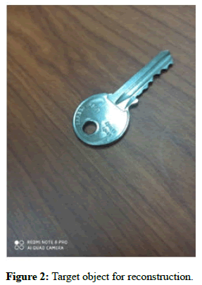
As mentioned above meshroom offers a nodal environment and each node will perform specific functions. The work consists in analyzing the measurement accuracy of 3D reconstruction using three different software: Meshlab, meshmixer and blender. The photos are taken through the xiaomi mobile phone readme note 8 pro. A small, detailed object is used for 3D reconstruction. As an object of study an ordinary office key is used and the reconstruction is done with meshroom software. The dimensions of the reconstructed object are determined and the measurement results will be compared with the real ones.
Initially the experiment was performed starting from a set of 40 photos that are randomly selected for the specified object. A white surface is used as the background. Photos are upload to meshroom, the process of executing the nodes went up to the node structure from motion and did not continue. This is due to the white background, which stops the processing of photos in the structure from motion node.
The background is changed as shown in Figure 2 randomly, 31 photos are obtained.
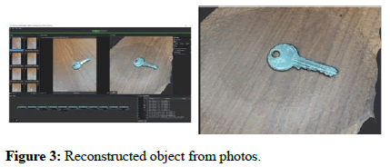
The reconstructed object using meshroom is shown in Figure 3.
Results and Discussion
It is noticed that the set with 31 photos as input, was all passed for further processing. The reconstructed 3D object is of a very good quality, as even the most complex part of the key, which is the part of the teeth, has been completely reconstructed and is easily distinguishable.
Case I
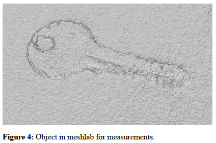
To determine the dimensions of the reconstructed object as specified above, meshlab will be used as the first case. The meshing that was generated by meshroom will be imported in meshlab and the result is shown in Figure 4.
As can be seen from the photo, the part of the teeth is not very clear visually in terms of quality, but the shape of the key is clearly visible, while in the final object obtained in meshroom, the teeth are visually very clear. With this final result so far that gives meshlab, the dimensions of the object in focus are determined. Substituting the new values at x, y and z plane, the distances to be measured will be of the same nature as those of the real object.
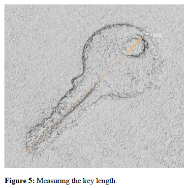
The length of the key measured using meshlab results in 5.4668 cm while the real length of the same distance is 5.5 cm, so the measurement error is 0.0332 cm as shown in Figure 5.
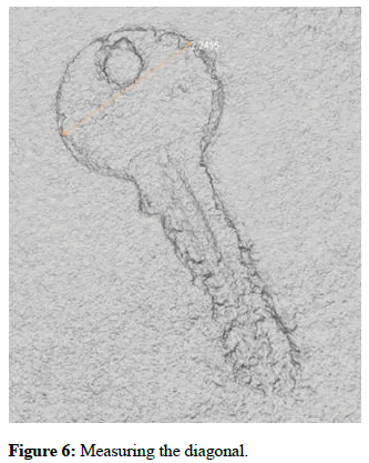
The distance of the two key points as in the picture above measured using meshlab results in 2.2455 cm while the real length of the same distance is 2.3 cm, the measurement error is 0.0545 cm as shown in Figure 6.
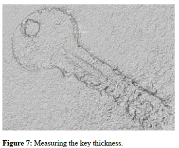
The height of the key measured by meshlab results in 0.203 cm while the real length of the same distance is 0.19 cm, the measurement error is 0.013 cm as illustrated in Figure 7.
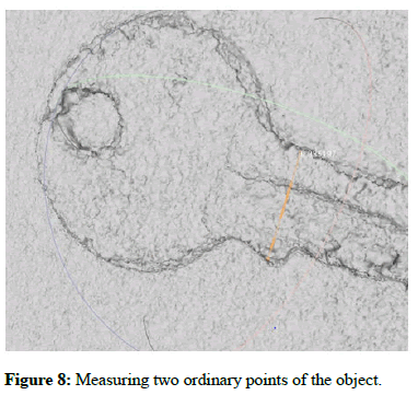
The distance of the two key points as illustrated in the Figure 8 measured using meshlab results in 0.935 cm while the real length of the same distance is 1 cm, the measurement error is 0.065 cm as shown.
Case II
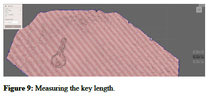
To determine the dimensions of the reconstructed object in meshroom, the meshmixer software will be used as the second case. Initially, the meshing that was generated by meshroom will be imported in meshmixer (Figure 9).
As can be seen from the photo, the part of the teeth is not very clear visually in terms of quality, but the shape of the key is clearly visible. The dimensions of the object in focus will be measured. Substituting the new values at x, y and z, now the distances to be measured will be of the same nature as those of the real object.
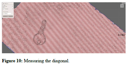
The total length of the key measured by meshmixer results in 5.515 cm while the real length of the same distance is 5.5 cm, the measurement error is 0.015 cm as shown in Figure 10.
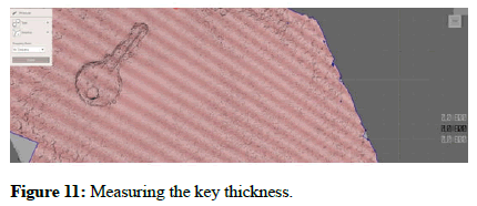
The distance of the two key points as in the picture above measured by meshmixer results in 2.2 cm while the real length of the same distance is 2.3 cm, the measurement error is 0.01 cm as shown in Figure 11.
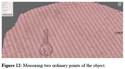
The height of the key measured by meshmixer results in 0.18 cm while the real length of the same distance is 0.19 cm, the measurement error is 0.01 cm as illustrated in Figure 12.
The distance of the two key points as in the picture above measured by meshmixer results in 0.954 cm while the real length of the same distance is 1 cm, the measurement error is 0.046 cm.
Case III
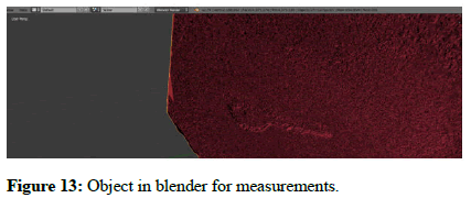
To determine the dimensions of the reconstructed object in meshroom, blender software is used as the third case. Initially the meshing that was generated by meshroom will be imported in blender and the result is as shown in Figure 13.
As can be seen from the result above, the object in focus is not visually clear at all in terms of quality. Therefore, since this is what blender software allows us, the distances for the target object cannot be determined, concluding that blender's performance for these types of small objects is not at a good level.
Case IV
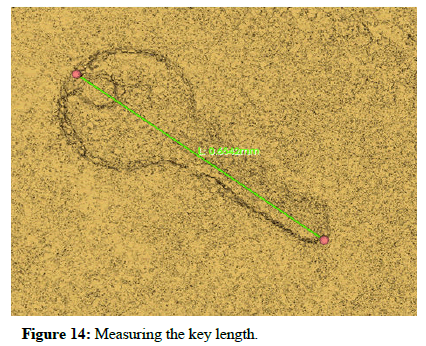
To determine the dimensions of the reconstructed object in meshroom, 3D Slicer software is used as the fourth case. Initially the meshing that was generated by meshroom will be imported in 3D slicer and the result is as shown in Figure 14.
As can be seen from the photo, the part of the teeth is not very clear visually in terms of quality. The dimensions of the object in focus will be measured.
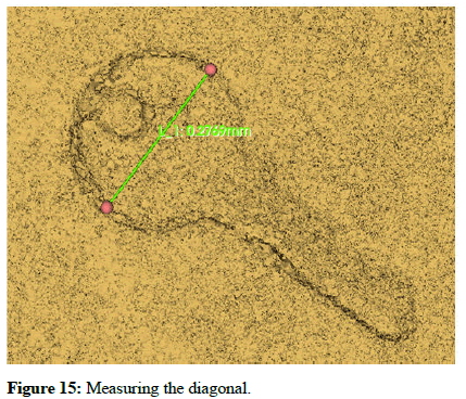
The total length of the key measured by 3D slicer results in 6.54 cm while the real length of the same distance is 5.5 cm, the measurement error is 1.04 cm as shown in Figure 15.
The distance of the two key points as in the picture above measured by 3D Slicer results in 2.7 cm while the real length of the same distance is 2.3 cm, the measurement error is 0.4 cm.
Performance comparison
The results of the measurements for four software used are shown in Table 1.
| Software | Visuality | Length error (cm) | Diagonal error (cm) | Thickness error (cm) | Two ordinary point error (cm) |
|---|---|---|---|---|---|
| Meshlab | Very clear | 0.0332 | 0.0545 | 0.013 | 0.065 |
| MeshMixer | Clear | 0.015 | 0.01 | 0.01 | 0.046 |
| Blender | Not clear | N/A | N/A | N/A | N/A |
| 3D Slicer | Clear | 1.04 | 0.4 | N/A | N/A |
Table 1: Performance comparison.
Conclusion
Changing the background from white in a suitable one brought the possibility of processing all meshroom nodes to generate the reconstructed 3D object. In this paper the focused was on small objects possibly with complex shapes.
The reconstructed object with a set of 31 photos resulted in a very good quality, visually very clear, complemented by content and clear contours. Having a known size element of the object, the reconstructed object is scaled. The dimensions of the small object are measured in four different software: MeshLab, meshmixer, 3D slicer and blender and a comparison is done between them. Experimental results show that dimensions of the object are obtained with high accuracy in a range of errors between 0.013 cm to 0.065 cm in meshlab and in a range of errors between 0.01 cm and 0.046 cm in meshmixer.
In conclusion, the best results are those provided using meshmixer software with an average error of 0.3 mm.
Conflict of Interest
The authors declare no conflict of interest.
Acknowledgment
This work was supported by the national agency for scientific research and innovation under the contract no. 831.
References
- Beall C, Lawrence BJ, Ila V, Dellaert F (2010) 3D reconstruction of underwater structures. IEEE Int Conf Intell Robots Syst 4418-4423.
- Mousavi V, Khosravi M, Ahmadi M, Noori N, Haghshenas S, et al. (2018) The performance evaluation of multi-image 3D reconstruction software with different sensors. Measurement 120:1-10.
- Li S, He Y, Li Q, Chen M (2018) Using laser measuring and SFM algorithm for fast 3D reconstruction of objects. J Russ Laser Res 39:591-599.
- Schops T, Sattler T, Hane C, Pollefeys M (2017) Large-scale outdoor 3D reconstruction on a mobile device. Comput Vis Image Underst 157:151-166.
- Cui B, Tao W, Zhao H (2021) High-precision 3D reconstruction for small-to-medium-sized objects utilizing line-structured light scanning: A review. Remote Sensing 13:4457.
- El-Hakim SF, Beraldin JA, Picard M, Godin G (2004) Detailed 3D reconstruction of large-scale heritage sites with integrated techniques. IEEE Comput Graph Appl 24:21-29.
[Crossref] [Google Scholar] [PubMed]
- Nguyen TT, Slaughter DC, Max N, Maloof JN, Sinha N (2015) Structured light-based 3D reconstruction system for plants. Sensors 15:18587-18612.
[Crossref] [Google Scholar] [PubMed]
- Dehghani H, Pogue BW, Shudong J, Brooksby B, Paulsen KD (2023) Three dimensional optical tomography:Resolution in small object imaging. Applied optics 42:3117-3128.
[Crossref] [Google Scholar] [PubMed]
- Chi S, Xie Z, Chen W (2016) A laser line auto-scanning system for underwater 3D reconstruction. Sensors 16:1534.
[Crossref] [Google Scholar] [PubMed]
- Tsioukas V, Patias P, Jacobs PF (2004) A novel system for the 3D reconstruction of small archaeological objects. Int Arch Photogramm 35:815-818.
- Gorpas D, Politopoulos K, Yova D (2007) A binocular machine vision system for three-dimensional surface measurement of small objects. Comput Med Imaging Graph 31:625-637.
[Crossref] [Google Scholar] [PubMed]
- Song L, Li X, Yang YG, Zhu X, Guo Q, et al. (2018) Structured-light based 3D reconstruction system for cultural relic packaging. Sensors 18:2981.
[Crossref] [Google Scholar] [PubMed]
- Karami A, Menna F, Remondino F (2022) Combining photogrammetry and photometric stereo to achieve precise and complete 3D reconstruction. Sensors 22:8172.
[Crossref] [Google Scholar] [PubMed]
- Makhsous S, Mohammad HM, Schenk JM, Mamishev AV, Kristal AR (2019) A novel mobile structured light system in food 3D reconstruction and volume estimation. Sensors 19:564.
[Crossref] [Googlescholar] [PubMed]
- Feldmann MJ, Tabb A (2022) Cost-effective, high throughput phenotyping system for 3D reconstruction of fruit form. Plant Phenome J 5:e20029.
 Spanish
  Chinese
  Russian
  German
  French
  Japanese
  Portuguese
  Hindi
Hindi 