Research Article, Biomater Med Appl Vol: 2 Issue: 2
Mechanical and Optical Properties of PCL Nanofiber Reinforced Alginate Hydrogels for Application in Corneal Wound Healing
Piotr Stafiej1,2, Florian Küng1,2, Friedrich E. Kruse2, Dirk W. Schubert1,3* and Thomas A Fuchsluger2
1Institute of Polymer Materials, Friedrich-Alexander-University Erlangen- Nürnberg, Martensstraße 7, 91054 Erlangen, Germany
2Department of Ophthalmology, Friedrich-Alexander-University Erlangen- Nürnberg, Schwabachanlage 6, 91054 Erlangen, Germany
3Bavarian Polymer Institute, Friedrich-Alexander-University Erlangen- Nürnberg, Dr.-Mack-Straße 77, 90762 Fürth, Germany
*Corresponding Author : Dirk W. Schubert
Institute of Polymer Materials, Friedrich-Alexander-University Erlangen-Nürnberg, Martensstraße 7, 91054 Erlangen, Germany
Tel: +499131 85 27752
Fax: +49 9131 85 28321
E-mail: dirk.schubert@fau.de
Received: May 10, 2018 Accepted: June 07, 2018 Published: June 14, 2018
Citation: Stafiej P, Küng F, Kruse FE, Schubert DW, Fuchsluger TA (2018) Mechanical and Optical Properties of PCL Nanofiber Reinforced Alginate Hydrogels for Application in Corneal Wound Healing. Biomater Med Appl 2:2. doi: 10.4172/2577-0268.1000118
Abstract
Treatment of corneal wounds in ophthalmology often involves the application of biological membranes, especially human amniotic membranes. As result of the biological background optical and mechanical properties can be inconsistent. Additionally, there is a huge need for serological screening to avoid transmission of diseases from donors. To replace the amniotic membrane we prepared nanofiber hydrogel compounds and evaluated their application-relevant properties. Nanofibers were prepared of polycaprolactone (PCL) and a blend with chitosan (CHI) by electrospinning. Nanofiber webs were produced either random, without specific orientation, or as multilayer webs of aligned fibers, where adjacent layers have a perpendicular fiber orientation to each other (aligned). Different treatment methods were evaluated for PCL scaffolds to decrease the water contact angle to obtain wettable membranes. The resulting nanofiber matrices were used to reinforce alginate hydrogels and thus to obtain scaffolds to replace the amniotic membrane as wound closure material for the cornea. We, therefore, investigated the transparencies of the manufactured compounds by UV-Vis spectroscopy and the readability through the membranes. As these membranes are to be sutured onto wounds, especially a human cornea, mechanical resistance against suture pullout was evaluated by suture retention test (SRT). Our results show the feasibility of producing nanofiber hydrogel compounds of pretreated PCL or blended PCL/CHI nanofibers and alginate hydrogel. All materials show high transparencies while only random nanofiber reinforced hydrogels showed increasing resistance to suture pullout. Reproducible compounds can be obtained in a quick, easy and inexpensive procedure maintaining properties that can be adjusted to the needs. Our membranes with random nanofiber scaffolds are able to mimic the properties of amniotic membranes, confirming their potential as the replacement application as wound cover material for the cornea.
Keywords: Sodium alginate; Hydrogel; Electrospinning; Nanofibers; Polycaprolactone; Cornea; Ophthalmology; Wound patch; Mechanical characterization
Introduction
The cornea serves two major functions in the human eye: It is the outermost part of the eye forming a shield to protect the eye against environmental influences and harms as chemicals, particles or bacteria. Additionally, the cornea delivers around 80 % of the eyes refractive power [1]. Chemical burns [2], mechanical trauma or corneal ulcerations endanger corneal integrity resulting in visual impairment. An inadequate healing of the cornea can lead to decreased or even loss of vision [3]. The human amniotic membrane is used as gold standard in the treatment of corneal injuries as it contains anti-angiogenic and anti-inflammatory molecules and reduces pain as well as discomfort on damaged and treated corneas [4]. Although the amniotic membrane is clinically used and possesses good properties for the treatment of injured corneas, several drawbacks like risk of infection and variations in mechanical and optical properties lead to a need for alternative materials [5].
Therefore hydrogels, made of natural polymers as polysaccharides, attract the attention of numerous scientists for use in biomedical application. Hydrogels have high biocompatibility because of their low interfacial free energy, reducing the tendency for proteins or cells to adhere [6]. Strong interactions between the tissue and the wound would lead to attachment of the patch and result in new injuries after detachment. Here synthetic wound patches have several advantages over biologically derived membranes regarding the reproducibility in their properties, the human and animal free origin [7] as well as the cheap and feasible production. Good grafts for corneal wound repair should have a high transparency. Enough mechanical stability has to be applied to the wound while maintaining structural integrity. Additionally, hydrogels can be used as drug delivery systems for controlled release without drug loss and the need of manual administration in form of drops or ointment [8]. Hydrogels provide prolonged corneal contact time ensuring good moisture management during application. Moisture is an important parameter of wound healing as poor moisture control and subsequent drying of the substrate affects the healing process and increases the risk of infections [9]. Nevertheless, hydrogels often suffer of weak mechanical stability as they are composed mainly of water. Therefore, reinforcement of hydrogels is essential to provide sufficient mechanical performance at the applied site [10].
In this study nanofiber matrices were prepared by electrospinning of polycaprolactone (PCL) and a blend of PCL with chitosan (CHI) on basis of our previous work [11]. Two types of matrices were obtained, nanofibers without orientation (random) as well as multilayer nanofiber matrices of aligned nanofibers, where adjacent layer have a perpendicular orientation to each other (aligned). These matrices were incorporated into alginate hydrogels to obtain mechanically reinforced hydrogels for treatment of corneal injuries. The prepared nanofiber hydrogel compounds (NFHC) were analyzed regarding their resistance against suture pullout and the transparency, both being crucial properties of good wound cover materials for corneal application.
Materials and Methods
Materials
Polycaprolactone (PCL; Mn=80 000 g*mol-1, Sigma Aldrich, Saint Louis, MO, USA) and chitosan (CHI; Carl Roth; Karlsruhe; Germany) were used for preparation of nanofiber scaffolds by electrospinning. Glacial acetic acid (>99%, VWR, Radnor, PA, USA), and formic acid (99%, VWR, Radnor, PA, USA) were used as solvents. Sodium hydroxide (NaOH; Carl Roth; Karlsruhe; Germany) was used for surface modification of unblended PCL nanofiber. Low viscosity sodium alginate was used for preparation of hydrogels (Sigma Aldrich, Saint Louis, MO, USA). Deionized water was used as solvent for sodium alginate and for cross linker solutions. Calcium chloride (Sigma Aldrich, Saint Louis, MO, USA) was used as Ca2+ source for crosslinking of hydrogels.
Electrospinning of nanofiber matrices
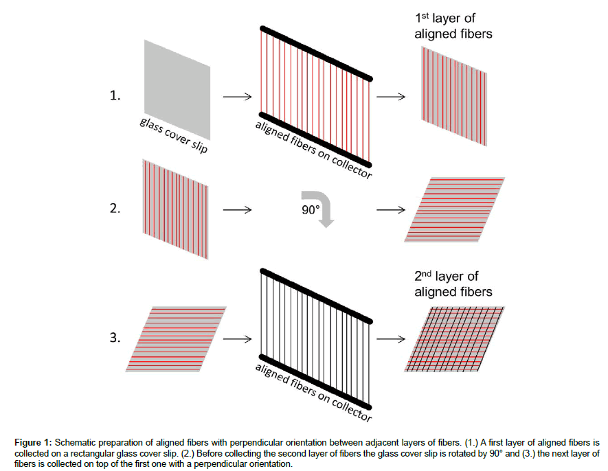
Nanofibers with parallel orientation and random ones were produced by electrospinning following a procedure described elsewhere [11]. Briefly, PCL and PCL blended with chitosan (PCL/ CHI) were dissolved in a mixture of acetic acid and formic acid (30%/70%) by stirring at least 4 hours at room temperature. For unblended PCL a concentration of 0.12 g/ml was used while the blend of PCL/CHI consisted of 0.11 g/ml PCL and 0.01 g/ml chitosan. The polymer solutions were poured into 10 ml glass syringes with a blunt steel needle with an inner diameter of 0.8 mm and mounted onto a syringe pump. The flow rate was set to 0.2 ml/h for aligned nanofiber production with a needle to collector distance of 15 cm and an applied voltage of 17 kV. For production of random nanofibers the flow rate was reduced to 0.15 ml/h, while all other settings were the same as in aligned nanofiber production. Random nanofiber webs (random: PCL-r, PCL/CHI-r) were obtained by use of a stainless steel plate wrapped in aluminum foil as collector, while webs with aligned nanofibers (aligned: PCL-a; PCL/CHI-a) were produced by use of a rotating cylinder with metallic bars with a 2.2 cm gap in between each pair of bars, as described elsewhere [12]. The speed of the rotating cylinder was set to 240 rpm, as higher rotational speeds would cause rupture of PCL/CHI fibers resulting from the higher rigidity of chitosan. Aligned nanofibers were detached from the collector and collected on rectangular glass coverslips (20 x 20 mm). The coverslip was rotated by 90° before the next layer was collected. This was repeated for different layer amounts to produce thicker nanofiber scaffolds (4 layers, 8 layers and 16 layers) consisting of aligned nanofibers layers with perpendicular orientation for adjacent layers (Figure 1). Random nanofiber matrices with different thicknesses (i.e. 5-10 μm, 10-20 μm, 20-30 μm and 30-45 μm) were produced by electrospinning for increasing durations (i.e. 30 min, 60 min and 120 min).
Figure 1: Schematic preparation of aligned fibers with perpendicular orientation between adjacent layers of fibers. (1.) A first layer of aligned fibers is collected on a rectangular glass cover slip. (2.) Before collecting the second layer of fibers the glass cover slip is rotated by 90° and (3.) the next layer of fibers is collected on top of the first one with a perpendicular orientation.
Surface modification of PCL nanofibers
As PCL itself is a highly hydrophobic polymer (water contact angle on random nanofiber web ≈ 130°), incorporation of aqueous solutions into the pores is challenging. To overcome these issues the hydrophobicity of PCL needed to be reduced by surface treatment. Therefore PCL scaffolds were treated with different methods including cold plasma treatment, UV irradiation, electron beam irradiation and chemical modification with sodium hydroxide. Respectively for cold plasma treatment, the kINPen® MED device was used with Argon gas [13,14]. The samples were mounted with needles and treated with cold plasma with a distance of 5 cm to the samples for durations up to 5 minutes. For UV irradiation the samples were placed in a 24-well plate without cover in a UV cross linker and treated with raising doses up to 600 mJ [15]. Electron beam irradiation was performed on samples stored in 24-well plates for dosages of 20, 29 and 38 kGy by Beta- Gamma-Service GmbH and Co. KG according to Zenkiewicz et.al. [16]. For chemical modification, the samples were placed in 24-well plates and incubated for 1 hour in a sodium hydroxide solution (1 M) according to Ghasemi-Mobarakeh et.al. [17]. Afterwards, the scaffolds were washed with deionized water thoroughly while exchanging the water several times for at least 12 hours. After treatment, all samples were washed with deionized water, placed on microscopic slides and stored in a fume hood for at least 24 h for drying. For each sample 5 contact angles were measured with water [OCA 20, DataPhysics Instruments GmbH, Filderstadt, Germany] using the sessile drop method with 2 μl drops of ultrapure water. The contact angle was measured after 5 sec with tangent leaning method. The obtained results were used to compare the effect of the different treatments on the water wettability of PCL scaffolds.
Characterization of nanofiber matrices and compounds by scanning electron microscopy
Random nanofiber matrices, as well as aligned matrices, were coated with a 7.5 nm thick gold layer using a sputter coater (Q150T Turbo-pumped Sputter Coater, Quorum Technologies Inc., Guelph, ON, Canada). Pictures with different magnifications ranging from 5000 X to 10000 X were taken with a scanning electron microscope (AURIGA CrossBeam; Carl Zeiss Microscopy GmbH, Oberkochen, Germany). Nanofiber thickness, as well as the orientation distribution, was analyzed using JMicroVision v.1.2.7 by measuring the diameter of typically 100 fibes for each sample type. The procedure to determine the true zero angle for the orientation distribution was determined by the following steps. Firstly the apparatus set zero angles (azimuth) was used to determine the orientation distribution. Secondly, due to the symmetry of the angle distribution, the true zero angles were subsequently shifted to the position of the median of the cumulative distribution functions. For analyzing the incorporation of the hydrogel into the nanofiber scaffolds, samples of the compounds were frozen in liquid nitrogen and cut into pieces. Afterwards, the samples were dried in ethanol solutions with raising the concentration of ethanol (20%, 40%, 60%, 80%, and 100%) before they were dried in the fume hood for 24 h. The samples were mounted on sample holders and coated with gold before SEM pictures were taken of the topside, the underside and the cross-section of each sample. The pictures were evaluated regarding the surface structure and the incorporation of the fibers into the compounds.
Preparation of alginate hydrogels and incorporation of nanofibers into these hydrogels
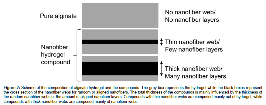
For the preparation of alginate hydrogels a 4 wt.% solution of sodium alginate was prepared in deionized water by stirring overnight. 1.5 ml of this solution were poured and spread on glass microscopic slides (5.6 x 2.6 cm) before placing them in a fume hood for drying overnight. The glass slides were placed in a 0.2 M CaCl2 solution for 15 mins for crosslinking. After crosslinking the hydrogels and compounds were washed with deionized water before circular samples with a diameter of 14 mm were punched out. For nanofiber hydrogel compounds the same procedure was used while pouring 1.5 ml alginate solution onto the glass slides with the dried nanofiber webs. To evaluate the influence of the nanofiber amount in the hydrogel compound onto the mechanical and optical properties, samples were prepared with different thicknesses of nanofiber webs. For the preparation of compounds with random nanofibers, nanofibers webs were used with thicknesses of 5-10 μm, 10-20 μm, 20-30 μm and 30- 45 μm. For the preparation of compounds with aligned nanofibers, 4 layers, 8 layers and 16 layers of aligned nanofibers were used, where adjacent layers had perpendicular orientations to each other (Figure 2).
Figure 2: Scheme of the composition of alginate hydrogel and the compounds. The grey box represents the hydrogel while the black boxes represent the cross section of the nanofiber webs for random or aligned nanofibers. The total thickness of the compounds is mainly influenced by the thickness of the random nanofiber webs or the amount of aligned nanofiber layers. Compounds with thin nanofiber webs are composed mainly out of hydrogel, while compounds with thick nanofiber webs are composed mainly of nanofiber webs.
Thickness measurement of the samples
The thickness of nanofiber scaffolds, hydrogels and nanofiber hydrogel compounds were measured using an electronic gauge (TESA Digico 1, TESA SA, Renens, Switzerland). The thickness of each sample was determined in the centre as well as in each quarter of the sample close to the rim. The nanofiber scaffold thickness was calculated as mean of these five measuring points. For suture retention tests the thickness of the alginate and the nanofiber hydrogel compounds was measured on the place where the sample was punctured for suturing (Figure 2).
Transparency of fiber webs, hydrogels and compounds
To visualize the transparency of the different samples a method described by Schubert et.al. [18] is used. Briefly, a line of text was printed repeatedly with increasing font sizes starting at 2 pt. up to 10 pt. on printer foil (here Calibri was used as font type). The wet samples of each type were placed on the text to check the readable font size. UV-Vis-spectroscopy was used additionally for quantitative transparency measurements. The samples were placed in 24 wellplates and covered with 1 ml of deionized water. The transparency was obtained for each sample by detecting the absorbance over the visual light spectra (400 nm-800 nm) in steps of 5 nm and converting the absorbance data into transmission data. For each type of sample, at least triplicates were measured and the mean of the spectra was calculated.
Suture retention tests of the different materials and combinations
For measuring the resistances of scaffolds against suture pullout a method developed by Kueng et al. [19] was used. Briefly, circles with two diameters (14mm and 12 mm) were printed out on paper. The circular samples of hydrogels and nanofiber hydrogel compounds were placed in these circles. After measuring the compound thickness at the suturing point, a 4-0 vicryl suture (Polyglactin 910, Johnson and Johnson Medical) was passed through each sample at the position of the inner circle with a distance of 1 ± 0.2 mm to the rim. The two ends of the suture were knotted using an overhand knot, the paper pattern was removed and the sample was clamped into the tensile testing machine (Zugfestigkeitsprüfmaschine Frank, K. Frank GmbH, and Mannheim, Germany). The suture loop was fixed with a bolt inside the testing machine equipped with a 50 N load cell. The suture retention strength test was run with a low constant deformation rate of 10 mm/min to ensure reliable data. The resulting maximum force, the force at rupture as well as the deformation lengths at maximum force and rupture force were recorded. To make sample measurements comparable maximum force was normalized to the sample thickness. Thus, maximum workload applicable towards the scaffolds prior to damage could be detected.
Statistical analysis
Any data was reported as mean with standard deviation if not mentioned differently.
Results
Analysis of nanofiber matrices
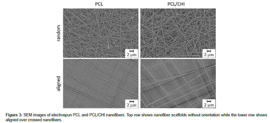
Random nanofiber webs and webs with aligned nanofiber layers, where adjacent layers have a perpendicular orientation to each other (aligned), were produced by electrospinning of PCL and PCL blended with Chitosan (PCL/CHI). SEM images of these samples were taken with magnifications of 5000 and 10000 for alignment and morphology analysis. Figure 3 shows representative pictures of PCL (left column) and PCL/CHI (right column) nanofibers for random (upper) and aligned orientation (lower), with a magnification of 5000.
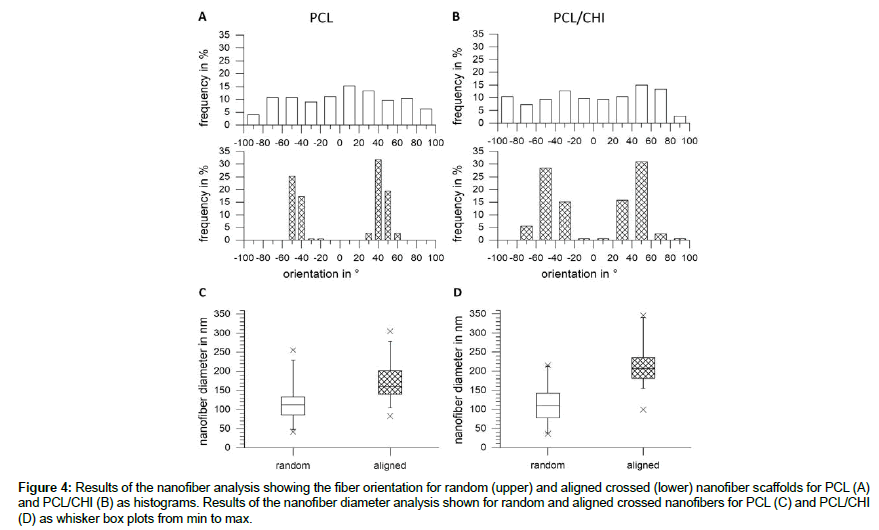
As can be seen on the images in Figure 3 nanofibers with a smooth appearance and almost no defects were obtained by electrospinning for all blends. In contrast to the nanofibers without orientation, a high alignment of nanofibers can be seen for aligned fibers. To analyze the morphology and the orientation of the nanofibers, pictures were analyzed regarding the orientation and the fiber diameter. The results are shown as histograms for the orientation (Figure 4 A and 4B), while the results of the fiber diameter analysis are shown as whisker box plots (Figure 4C and 4D). The orientation histograms for random PCL as well as for PCL/CHI nanofibers (upper row) show a broad spreading of fiber orientations while the aligned nanofibers (lower row) show two orientation groups at around ± 30-50° for PCL and two orientation groups at around ± 30-70° for PCL/CHI. The fiber diameter analysis shows fiber diameters ranging from 42 to 255 nm for random and 83 to 305 nm for aligned PCL nanofibers (Figure 4C) with 50% of data in between 86 and 133 nm for random and 50% of data in between 140 and 201 nm for aligned nanofibers. For PCL/ CHI nanofibers a diameter distribution (Figure 4D) can be seen ranging from 36 to 215 nm for random and 99 to 345 nm for aligned nanofibers while 50% of data are found in between 77 to 142 nm for random and 181 to 236 nm for aligned nanofibers.
Figure 4: Results of the nanofiber analysis showing the fiber orientation for random (upper) and aligned crossed (lower) nanofiber scaffolds for PCL (A) and PCL/CHI (B) as histograms. Results of the nanofiber diameter analysis shown for random and aligned crossed nanofibers for PCL (C) and PCL/CHI (D) as whisker box plots from min to max.
Surface modification of PCL nanofiber scaffolds
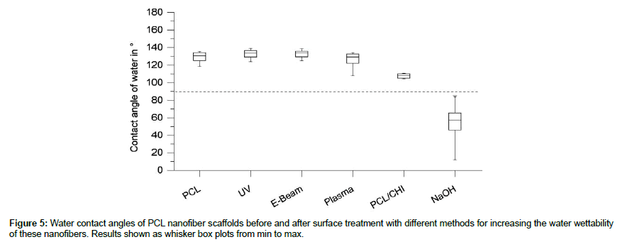
Different methods were applied on PCL nanofiber scaffolds to increase the water wettability of PCL to facilitate the incorporation of hydrogels into these scaffolds. The results of the water contact angles of PCL after treatment are shown in Figure 5 as whisker box plots. Untreated PCL shows high water contact angles in between 118° and 135°, indicating the high hydrophobicity of these scaffolds. UV irradiation of these scaffolds with dosages of up to 600 mJ did not show changes to the water wettability with values in between 124° and 139°. Similar values were obtained for electron beam irradiation with contact angles around 125°-139° as well as for cold plasma treatment with argon with contact angles in between 118° and 134°. The blending of PCL with 10% chitosan (relative to the mass of PCL) decreased the water contact angle significantly to 104°-110°. Although these values indicate hydrophobicity (contact angles>90°), the application of bigger water drops (>100 μl) showed a good water wettability of these scaffolds, due to higher gravity forces for bigger drops. Chemical treatment of PCL with 1 M sodium hydroxide solution showed the most promising results with water contact angles in between 12° and 85°. As SEM analysis did not show changes in fiber morphology, blending of PCL with chitosan and the treatment of PCL with sodium hydroxide were chosen as methods for the preparation of nanofiber scaffolds for use in the nanofiber hydrogel compounds.
Integration of nanofiber scaffolds into alginate hydrogels
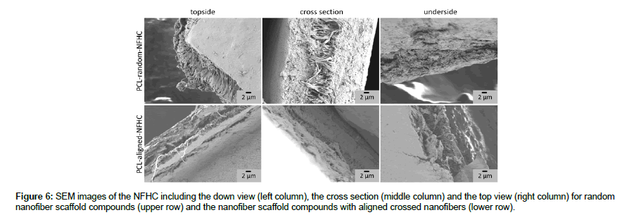
After incorporation of nanofiber scaffolds into the alginate hydrogel, the samples were dried by washing steps with ethanol solutions with raising ethanol concentrations before drying the samples in the fume hood for 12 h. The samples were cut into quarters and coated with gold for SEM analysis. Figure 6 shows representative SEM pictures of the nanofiber hydrogel compounds prepared with random PCL nanofiber webs with a thickness of around 20 to 30 μm (upper row) and aligned PCL nanofiber webs with 16 layers (lower row). The total thicknesses of the NFHC were approximately 80-110 μm in the swollen state. Figure 6 shows SEM pictures from the topside (left column), the cross-section (middle column) and the underside (right column). As can be seen in the pictures both, random and aligned nanofiber webs were well incorporated into the hydrogel, as the hydrogel penetrated not only into the pores but formed a layer of hydrogel under as well as on top of the nanofibers. The hydrogel surfaces show a smooth appearance while no real pore structure can be seen in the cross-sections. This results from collapsing of the 3D structure of the hydrogel during drying. As result of cutting the samples, the forces applied onto the nanofibers caused an elongation of these and lead to an aligned appearance in the random fiber webs, as can be seen in the topside of random nanofiber hydrogel compounds.
Optical properties of alginate hydrogel and the nanofiber hydrogel compounds
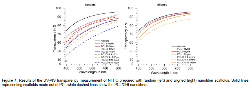
As the transparency of the nanofiber hydrogel compounds is a crucial property for application on the cornea, we used two methods for the transparency measurements of our compounds. Figure 7 sums up the transparency spectra of the compounds in the visual light area ranging from 400 to 800 nm measured with a UV-Visspectrophotometer in triplicates for each compound. The left diagram sums up the transparency spectra for the compounds prepared with random nanofiber webs while results for aligned nanofiber hydrogel compounds are shown in the right diagram. Spectra for scaffolds made out of PCL are shown as solid lines while spectra for PCL/ CHI compounds are shown as dashed lines. Alginate was measured as reference material and is shown as the solid black line in both diagrams. The transparency spectra for all samples show the same shape of the curve with a low transparency at a small wavelength and an increase in transparency with an increase in wavelength. As most significant parameter the transparency at 400 nm was used for further comparisons. No significant differences could be measured in between hydrogel compounds composed of either PCL or PCL/CHI nanofiber scaffolds. As can be seen in the left diagram the thickness of the nanofiber scaffold affects the transparency of the compounds showing a decrease in transparency with an increase in nanofiber scaffold thickness. Compounds with thin nanofiber webs (5-20 μm) show only small differences in between PCL and PCL/CHI compounds, while the difference increases with the web thickness. This difference can be explained by inhomogeneity in the preparation of thicker nanofiber scaffolds (>20 μm) by electrospinning independent from the polymer. Compounds containing nanofiber webs with a thickness up to 30 μm show transparencies over 50% at 400 nm, while only the samples of the PCL/CHI compound with nanofiber web thicknesses higher than 30 μm lead to an transparency of around 46% at 400 nm. The same behaviour can be seen for compounds with aligned nanofibers with only small differences in between compounds made out of PCL compared to PCL/CHI. Nanofiber hydrogel compounds with aligned nanofibers show also the same trend as for random nanofiber compounds having lower transparencies for thicker nanofiber webs. The lowest transparency results were measured for aligned nanofibers of PCL/CHI with 16 layers resulting in a transparency of around 60% at 400 nm.
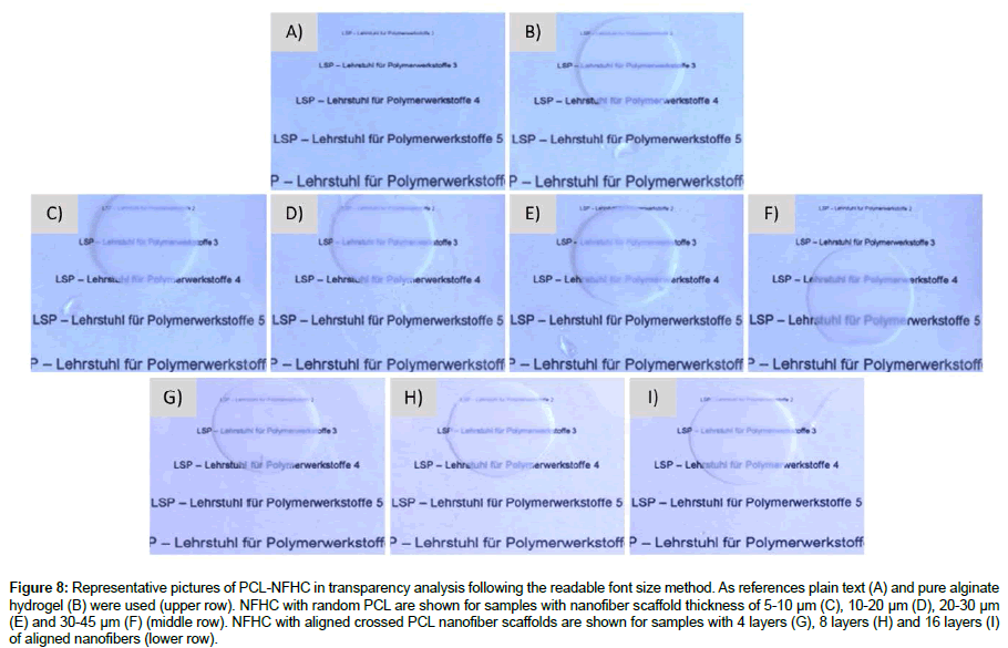
After measuring the UV-Vis transparencies, the samples were placed on printer foil on which we printed text lines in increasing font sizes. By placing the materials on top of these text lines the readable font size can be evaluated. This method gives us an evidence for the transparency of the materials, showing higher transparencies with decreasing readable font sizes. The plain texts, as well as pure alginate hydrogel, were used as references and pictures were taken with a light microscope with a magnification of 10. The upper row in Figure 8 shows the plain text (A) and the alginate hydrogel (B), while the middle row shows the pictures of NFHC made with webs of random PCL nanofibers with increasing thicknesses from left to right. In the lower row, the pictures are shown for NFHCs made with aligned nanofibers of PCL with 4 to 16 layers (from left to right). As shown, the readability of the text lines is very high, showing readable font sizes of 2 for NFHCs with random nanofiber webs of 5-10 μm and 10-20 μm, the readable font size of 3 for NFHCs with 20-30 μm nanofiber web and font sizes of 4-5 for NFHCs with 30-45 μm nanofiber web thickness. For NFHCs prepared with aligned nanofibers the readable font size is 2 for 4 to 8 layers and 3 for NFHCs with 16 layers of nanofibers. These results represent the high transparency of the developed NFHCs throughout the whole range.
Figure 8: Representative pictures of PCL-NFHC in transparency analysis following the readable font size method. As references plain text (A) and pure alginate hydrogel (B) were used (upper row). NFHC with random PCL are shown for samples with nanofiber scaffold thickness of 5-10 μm (C), 10-20 μm (D), 20-30 μm (E) and 30-45 μm (F) (middle row). NFHC with aligned crossed PCL nanofiber scaffolds are shown for samples with 4 layers (G), 8 layers (H) and 16 layers (I) of aligned nanofibers (lower row).
Suture ability of alginate hydrogels and the nanofiber hydrogel compounds
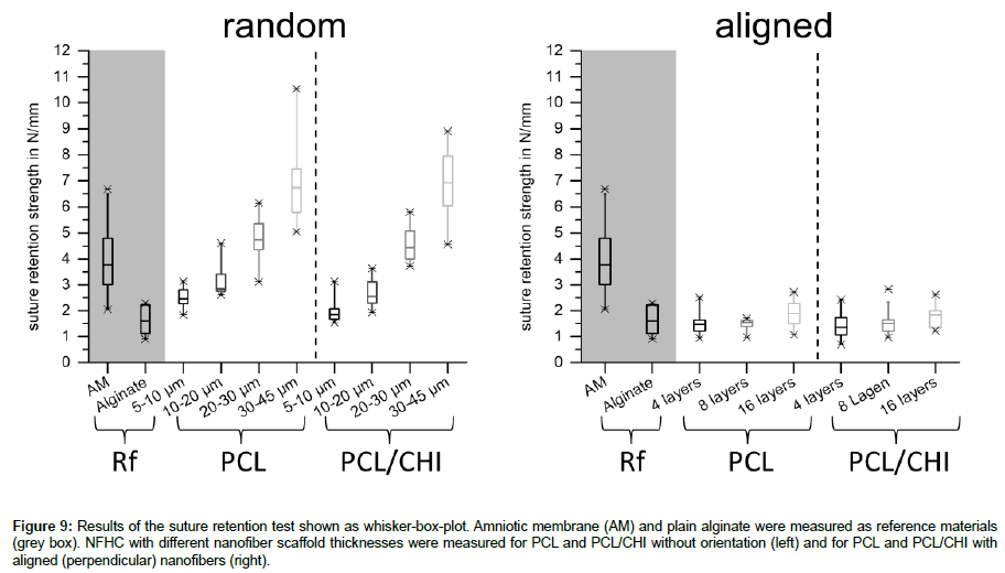
As the developed NFHCs are planned to be sutured on top of the cornea, the resistance of the materials against suture pullout is as crucial as the transparency. Therefore the suture ability was evaluated by measuring the maximum resistance force of each sample and normalizing it to the sample thickness. The left diagram in Figure 9 shows the suture retention strength of the used references, the amniotic membrane [19] and pure alginate as well as the NFHCs prepared with random nanofiber webs of PCL and PCL/CHI. The right diagram in Figure 9 sums up the results for the references and the NFHCs prepared with aligned nanofiber webs of PCL and PCL/ CHI. As shown in Figure 9 (left diagram), an increase of random nanofiber web thickness leads to an higher suture ability of the compounds for both materials, PCL and PCL/CHI. NFHCs with random nanofiber webs of 20-30 μm thickness do mimic the resistance of the amniotic membrane against suture pullout well, representing a good replacement of this biological membrane in relation to the suture ability. As shown in Figure 9 (right diagram), an increase of aligned nanofiber layers does not increase the suture ability of the tested compounds with up to 16 layers. All compounds with aligned nanofibers, PCL as well as PCL/CHI, show a suture retention strength in the range of pure alginate, which is only half the suture retention strength of the amniotic membrane.
Figure 9: Results of the suture retention test shown as whisker-box-plot. Amniotic membrane (AM) and plain alginate were measured as reference materials (grey box). NFHC with different nanofiber scaffold thicknesses were measured for PCL and PCL/CHI without orientation (left) and for PCL and PCL/CHI with aligned (perpendicular) nanofibers (right).
Discussion
Preparation and characterization of nanofiber hydrogel compounds (NFHC)
In this study, we described the preparation of nanofiber hydrogel compounds made out of electrospun nanofibers and alginate hydrogel. These compounds were characterized regarding their transparencies and their resistances against suture pullout as crucial properties for the application in wound treatment of the ocular surface.
As PCL is a hydrophobic polymer with a water contact angle of around 130°, different treatments were evaluated to increase the water wettability of the nanofiber webs for better incorporation of hydrogels into the membranes (Figure 5). PCL nanofiber webs without orientation were treated either with UV irradiation dosages of up to 600 mJ, with electron beam irradiation up to 38 kGy, treated with cold argon plasma for up to 5 min or hydrolyzed with sodium hydroxide (1M) for 1 hour at room temperature. In contrast to the literature [13,16,20] water contact angle analysis did not show an increase in water wettability for the irradiation with UV- and electron beam irradiation or the treatment with cold plasma. Only the treatment with sodium hydroxide lead to water contact angles lower than 90° representing a very good water wettability of the nanofiber webs. This is in accordance with the literature [17], although only 1 hour of sodium hydroxide treatment was necessary for reaching contact angles under 90° in our study. This might be explained by the fiber diameter, which was half the diameter in this study compared to the literature, also considering the resulting increase of the PCL surface area. Additionally, samples prepared of the blend of PCL and chitosan showed lower contact angles (approx. 110°) compared to pure PCL, which are still found in the hydrophobic area, but an application of larger water drops (>100 μl) showed a good penetration of water into the pores. Comparable results were obtained by other groups [21], presenting a contact angle decrease for blends of PCL with chitosan to around 117°. On this basis, the blend of PCL and chitosan, as well as the treatment of PCL with sodium hydroxide, were chosen for the preparation of compounds with alginate hydrogels.
The incorporation of the alginate hydrogel showed good penetration through the nanofiber pores for random and for aligned crossed nanofibers of both materials (Figure 6). The formation of hydrogel layers on top and under the nanofiber webs ensure the incorporation of the nanofibers into the core of the hydrogel. These compounds showed total thicknesses of 80 to 110 μm in the swollen state similar to the thickness of the amniotic membranes, which is found to be in between 20 and 100 μm depending on the source as well as the preparation methods [22]. Nanofiber hydrogel compounds with smooth surfaces were obtained by this method giving us different materials for the evaluation of the properties in regard to the transparency and the suture ability.
Analysis of the transparency and the suture ability of the nanofiber hydrogel compounds
A good wound cover material for corneal application as the replacement for an amniotic membrane requires high transparency and adequate mechanical stability to resist suture pullout during suturing of the membrane to the surface of the cornea.
To evaluate the suture ability of these membranes, a suture retention test (SRT) was performed on all materials. The resistance to suture pullout of these membranes was measured as maximum force and compared to the amniotic membrane (AM) and pure alginate (Figure 9). Scaffolds that were made of reinforced hydrogels with random nanofiber webs showed an increase in suture retention strength with increasing nanofiber web thickness. This result is comparable to the findings of other studies, which showed an increase in mechanical strength of hydrogel while increasing the amount of nanofibers [10]. Scaffolds with nanofiber web thicknesses of 20-30 μm showed enough mechanical strength to mimic the strength of the amniotic membrane. No significant differences could be seen in between scaffolds made out of PCL or PCL/CHI. Nevertheless, scaffolds made from aligned nanofiber multilayers, where adjacent layers have a perpendicular orientation to each other, did not show an increase in suture retention strength with increasing amount of fiber layers. This might be caused by the missing adherence between the fibers as well as between the fiber layers. As the fibers are collected on the glass coverslip after drying on the collector, no connections can be built in between the fibers, leading to more flexible fibers with bigger pores but lower resistance against mechanical manipulation. In contrast to this, nanofibers produced as random web get into contact with other fibers while containing a minimal amount of solvent, leading to adhering fibers at the contact points. The nanofiber hydrogel compounds made out of random nanofiber webs get stiffer but more resistant against mechanical manipulation (i.e. suture pull out), as result of these crosslinks.
Conclusion
In this study, we developed compounds of hydrogels reinforced with electrospun nanofibers without orientation and with aligned orientation. SEM pictures showed good incorporation of PCL and PCL/CHI nanofiber scaffolds into the hydrogel, leading to membranes with high transparency for all compounds. The mechanical resistance against suture pullout was measured for all materials showing an increasing resistance of the compound with increasing amount of random nanofibers. Scaffolds with random nanofibers with a web thickness of 20-30 μm showed enough mechanical resistance to mimic the behaviour of the clinical gold standard, the amniotic membrane. Although aligned nanofibers could be also incorporated into the hydrogel and showed high transparencies, no increase in mechanical stability could be obtained with the increase of fiber amount. As our compounds of random nanofiber reinforced hydrogels showed good mechanical resistance while maintaining high transparencies, our NFHCs are promising candidates for replacing biological scaffolds as the amniotic membrane for application as wound cover for the cornea and the ocular surface.
Acknowledgment
We thank SFB TRR 225 for evaluating specific applications opportunities.
References
- Studer H, Larrea X, Riedwyl H, Buchler P (2010) Biomechanical model of human cornea based on stromal microstructure. J Biomech 43: 836-842.
- Singh P, Tyagi M, Kumar Y, Gupta KK, Sharma PD (2013) Ocular chemical injuries and their management. Oman J Ophthalmol 6: 83-86.
- Grinstaff MW (2007) Designing hydrogel adhesives for corneal wound repair. Biomaterials 28: 5205-5214.
- Mamede AC, Carvalho MJ, Abrantes AM, Laranjo M, Maia CJ, et al. (2012) Amniotic membrane: from structure and functions to clinical applications. Cell Tissue Res 349: 447-458.
- Feng Y, Borrelli M, Reichl S, Schrader S, Geerling G (2014) Review of alternative carrier materials for ocular surface reconstruction. Curr Eye Res 39: 541-552.
- Syed KH Gulrez, Al-Assaf S, Phillips GO (2011) Hydrogels: Methods of Preparation, Characterisation and Applications. In: Carpi PA, editor. Progress in Molecular and Environmental Bioengineering - From Analysis and Modeling to Technology Applications: InTech
- Gallagher AG, Alorabi JA, Wellings DA, Lace R, Horsburgh MJ, et al. (2016) A Novel Peptide Hydrogel for an Antimicrobial Bandage Contact Lens. Adv Healthc Mater 5: 2013-2018.
- Anumolu SS, DeSantis AS, Menjoge AR, Hahn RA, Beloni JA, et al. (2010) Doxycycline loaded poly(ethylene glycol) hydrogels for healing vesicant-induced ocular wounds. Biomaterials 31: 964-974.
- Patchan MW, Chae JJ, Lee JD, Calderon-Colon X, Maranchi JP, et al. (2016) Evaluation of the biocompatibility of regenerated cellulose hydrogels with high strength and transparency for ocular applications. J Biomater Appl 30: 1049-1059.
- Jang J, Lee J, Seol YJ, Jeong YH, Cho DW (2013) Improving mechanical properties of alginate hydrogel by reinforcement with ethanol treated polycaprolactone nanofibers. Compos Part B-Eng 45: 1216-1221.
- Stafiej P, Kung F, Thieme D, Czugala M, Kruse FE, et al. (2017) Adhesion and metabolic activity of human corneal cells on PCL based nanofiber matrices. Mater Sci Eng C Mater Biol Appl 71: 764-770.
- Doergens A, Roether JA, Dippold D, Boccaccini AR, Schubert D (2015) Identifying key processing parameters for the electrospinning of aligned polymer nanofibers. Mater Lett 140: 99-102.
- Cheng C, Zhang LY, Zhan RJ (2006) Surface modification of polymer fibre by the new atmospheric pressure cold plasma jet. Surf Coat Tech 200: 6659-6665.
- Wende K, Bekeschus S, Schmidt A, Jatsch L, Hasse S, et al. (2016) Risk assessment of a cold argon plasma jet in respect to its mutagenicity. Mutat Res Genet Toxicol Environ Mutagen 798-799: 48-54.
- Monteiro N, Martins A, Pires R, Faria S, Fonseca NA, et al. (2014) Immobilization of bioactive factor-loaded liposomes on the surface of electrospun nanofibers targeting tissue engineering. Biomater Sci 2: 1195-1209.
- Zenkiewicz M, Rytlewski P, Czuprynska J, Polanski J, Karasiewicz T, et al. (2008) Contact angle and surface free energy of electron-beam irradiated polymer composites. Polimery-W 53: 446-451.
- Ghasemi-Mobarakeh L, Prabhakaran MP, Morshed M, Nasr-Esfahani MH, Ramakrishna S (2010) Bio-functionalized PCL nanofibrous scaffolds for nerve tissue engineering. Mat Sci Eng C-Mater 30: 1129-1136.
- Schubert DW, Kaschta J, Seidl S, Kunzelmann P (2016) Binary and Ternary Blends of Polypropylene Types - Influence on the Homogeneity of Biaxial-Oriented Films. Macromol Symp 365: 87-94.
- Kung F, Schubert DW, Stafiej P, Kruse FE, Fuchsluger TA (2016) A novel suture retention test for scaffold strength characterization in ophthalmology. Mat Sci Eng C-Mater 69: 941-946.
- Kaczmarek H, Kowalonek J, Szalla A, Sionkowska A (2002) Surface modification of thin polymeric films by air-plasma or UV-irradiation. Surf Sci 507: 883-888.
- Prasad T, Shabeena EA, Vinod D, Kumary TV, Anil Kumar PR (2015) Characterization and in vitro evaluation of electrospun chitosan/polycaprolactone blend fibrous mat for skin tissue engineering. J Mater Sci Mater Med 26: 5352.
- Connon CJ, Doutch J, Chen B, Hopkinson A, Mehta JS, et al. (2010) The variation in transparency of amniotic membrane used in ocular surface regeneration. Br J Ophthalmol 94: 1057-1061.
 Spanish
  Chinese
  Russian
  German
  French
  Japanese
  Portuguese
  Hindi
Hindi 