Spanish
  Chinese
  Russian
  German
  French
  Japanese
  Portuguese
  Hindi
Hindi Research Article, Biomater Med Appl Vol: 1 Issue: 2
Peristaltic Flow in a nonUniform Channel with Heat and Mass Transfer
Saima Noreen*
Department of Forestry and Biodiversity, Tripura University, Suryamaninagar, Agartala, India
*Corresponding Author : Saima Noreen
Department of Mathematics, Comsats Institute of Information Technology, Islamabad, Pakistan
Tel: +92-051 9044823
E-mail: laurel_lichen@yahoo.com
Received: October 03, 2017 Accepted: October 10, 2017 Published: October 17, 2017
Citation: Noreen S (2017) Peristaltic Flow in a non-Uniform Channel with Heat and Mass Transfer. Biomater Med Appl 1:2.
Abstract
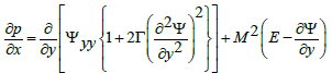
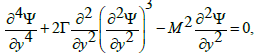
The combined effect of heat and mass transfer on the peristaltic flow of fourth-grade fluid in a non-uniform channel has been investigated. Flow analysis has been carried out in the presence of an induced magnetic field. The governing flow equations have been transformed in a wave frame. The arising equations have been solved for the stream function, pressure gradient, temperature, concentration, magnetic force function, induced a magnetic field and current density. The role of embedded parameters is displayed and discussed.
Keywords: Induced magnetic field; Heat and mass transfer; Fourth-grade fluid; Non-uniform channel
Introduction
The study of peristaltic mechanism has become popular among the researchers during the last four decades. This is because of its wide ranging industrial and physiological applications. In physiological processes it is used by the body to propel or mix the contents of the tube, for instance, in gastrointestinal tract, ureter, the bile duct, and other glandular ducts. Industrial use of peristaltic pumping in finger and roller pumps is quite obvious. Engineers adopted this processes to pump corrosive materials and fluids that must be kept away from pumping machinery. Further the transport of toxic liquid is met by the nuclear industry so as to not contaminate the environment [1]. Since the seminal work of Latham [2] several theoretical and experimental investigations have been carried out in order to understand the peristaltic flows of hydrodynamic fluids under varied assumptions of long wavelength, low Reynolds number, small wave amplitude etc. Although the literature on the topic is extensive but few recent investigations can be mentioned by the studies [3-10].
The peristaltic flows in the presence of magnetic field have also been examined. Agrawal and Anwaruddin [11] have studied the peristaltic flow of a blood under long wavelength and low Reynolds number assumption. Kothandapani and Srinivas [12] reported the peristaltic transport of a magnetohydrodynamic (MHD) Jeffrey fluid under the effect of magnetic field in an asymmetric channel. Mekheimer [13,14] and Hayat et al. [15] discussed the peristaltic flows of couple stress, micropolar and third grade fluids in the presence of an induced magnetic field. Elmaboud [16] analyzed the induced magnetic field effect on the peristaltic flow in an annulus. Since most of the ducts in physiology are non-uniform so Pandey and Chaube [17] studied the peristaltic transport of a viscoelastic fluid in a tube of non-uniform cross section. Mekheimer [18] reported peristaltic flow of blood under effect of magnetic field in a non-uniform channel.
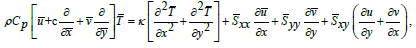
The interaction of peristalsis with heat and mass transfer is an important topic which has been given little attention so far. Srinivas et al. [19] investigated mixed convective peristaltic transport in an asymmetric channel. Srinivas and Muthuraj [20] presented peristaltic transport of a non-Newtonian fluid with chemical reaction and space porosity. Hayat et al. [21] discussed the role of heat transfer on the MHD peristaltic flow in a porous space. Kothandapani and Srinivas [22] have studied the influence of wall properties in the MHD peristaltic transport with heat transfer and porous medium. Ogulu [23] studied heat and mass transport of blood in a single lymphatic blood vessel with uniform magnetic field. Mekheimer and elmaboud [24] had reported the influence of heat transfer and magnetic field on peristaltic transport of Newtonian fluid in a vertical annulus. The influence of wall properties on the MHD peristaltic flow of a Maxwell fluid with heat and mass transfer in a symmetric channel has been investigated by Hayat and Hina.
The purpose of present research is to discuss the simultaneous effects of an induced magnetic field and heat and mass transfer on the peristaltic flow of a fourth grade fluid in a non-uniform channel. The considered fluid can predict the shear thinning/shear thickening effects. To the best of our knowledge, this problem has not been investigated yet. The paper is arranged as follows. Sections two and three provide the mathematical formulation and perturbed solution of the problem. Graphical discussion is presented in section four while the concluding remarks are given in section 5.
Formulation
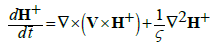
An incompressible magneto hydrodynamic (MHD) fourth grade fluid in a non-uniform channel is considered. X̄ Axis is chosen in the direction of wave propagation and Ȳ transverse to it. A constant magnetic field of strength H0 acts in the transverse direction which results in an induced magnetic field  The total magnetic field is
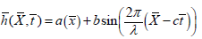
  The following expression describes the geometry of the channel wall
 (1)
(1)
With
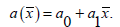
Here a0 is half width at any inlet, (a1 <<1) is constant, λ is the wavelength, a indicates the channel half width at any axial distance x̄, b the wave amplitude, c the wave speed and t the time.
In fixed frame the fundamental equations governing the flow are
∇⋅V = 0 (2)
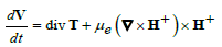
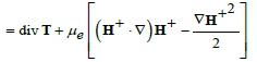 (3)
(3)
 (4)
(4)
 (5)
(5)
 (6)
(6)
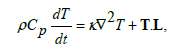
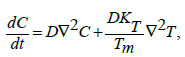
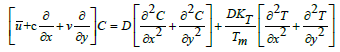
in which  is the magnetic diffusivity, Cp the specific heat, T the temperature, D the coefficient of mass diffusivity, Tm the mean temperature, KT the thermal diffusion ratio,C the concentration, K̄ the thermal conductivity and the Cauchy stress tensor T̄ and extra stress tensor S̄ are
 (7)
(7)
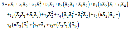 (8)
(8)
 (9)
(9)
 (10)
(10)
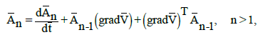
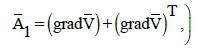
Where  and
and  are the material constants,
  the Rivilin-Ericksen tensors,
 the material derivative, μ the viscosity, λr the trace, T in the superscript is the matrix transpose, p the pressure and Ī the identity tensor. The velocity V̄ for two-dimensional flow is of the form
 (11)
(11)
And the Maxwell’s relations are
 (12)
(12)
 (13)
(13)
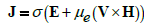 (14)
(14)
in which J, μe, σ , E and H represent the electric current density, the magnetic permeability, the electrical conductivity, the electric field and the magnetic field respectively.
The relations between the fixed frame  and wave frame can be written as
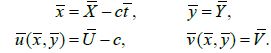 (15)
(15)
Here  and
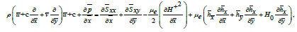
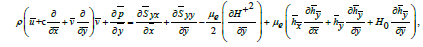
and  depict the velocity components in the fixed and wave frames respectively. The two-dimensional equations in the wave frame are
 (16)
(16)
 (17)
(17)
 (18)
(18)
 (19)
(19)
 (20)
(20)
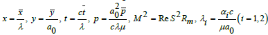
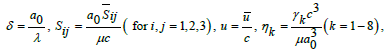
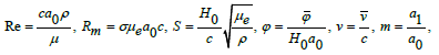
We set the dimensionless quantities as
 (21)
(21)
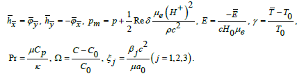
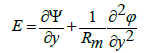
In above definitions Pr , δ , Re, Rm, S and M denote the Prandtl, wave, Reynolds, magnetic Reynolds, Stommer’s and Hartman numbers respectively and the total pressure pm is sum of ordinary and magnetic pressures, E the electric field strength, m the nonuniformity parameter, γ the temperature, Ω the concentration and φ the magnetic force function. Further T0 and C0 denote the temperature and concentration at y=h.
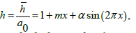
Equation (1) in dimensionless form reduces to
 (22)
(22)
In which the amplitude ratio α is equal to b/a0.
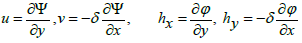
Putting
 (23)
(23)
Equations (2) automatically satisfied and equations (3-20) can be easily arranged as
 (24)
(24)
 (25)
(25)
 (26)
(26)
 (27)
(27)
 (28)
(28)
Where, the subscripts depict the partial differentiation. Adopting the long wavelength and low Reynolds number procedure we obtain
 (29)
(29)
 (30)
(30)
 (31)
(31)
 (32)
(32)
 (33)
(33)
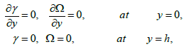
With the subjected boundary conditions
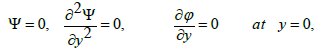
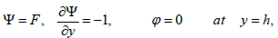 (34)
(34)
where p ≠ p( y) and F is the dimensionless time mean flow rate in the wave frame which can be related to dimensionless time mean flow rate θ in the laboratory frame by θ = F +1,
 (35)
(35)
From Equation (8) (29) and (30) we obtain
 (36)
(36)
 (37)
(37)
Where  is used for the Deborah number.
Perturbation Solution Writing
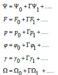 (38-43)
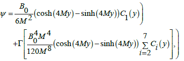
And inserting into Equations (31, 32, 34, 36, and 37) we get the zero and first order systems. Solving the resulting zero and first order systems one obtains
 (44)
(44)
 (45)
(45)
 (46)
(46)
 (47)
(47)
 (48)
(48)
Where the values of the involved  and
and  can be given through algebraic computations and
 has been used in the above expressions. To save space we avoid to present the values of Al, Bk, Ci and Lj here.
The definitions of dimensionless axial induced magnetic field hx, current density Jz and pressure rise ΔPλ are
 (49)
(49)
 (50)
(50)
 (51)
(51)
Graphical Results and Discussion
In this section we present the effects of various parameters (i.e., material parameter Γ non-uniformity parameter m, Hartman number M, Brinkman number Br and Schmidt number Sc) on the temperature γ, current density Jz, axial induced magnetic field hx pressure gradient dp/dx pressure rise ΔPλ and axial velocity μ. Hence Figures 1-6 have been displayed.

Figure 1a: The pressure gradient dp/dx versus x for α=0.1, M=2.5, m=0.1, E=1 and θ=1.2.

Figure 1b: The pressure gradient dp/dx versus x for α=0.2, T=0.01, M=2.0, E=1 and θ= -1.1.

Figure 2a: The pressure rise ΔPλ versus flow rate θ for m=0.1, α=0.2, M=1.5, and E=1.

Figure 2b: The pressure rise ΔPλ versus flow rate θ for M=1.5, α=0.2, T=0.001and E=1.

Figure 3a: The axial velocity u for x=0.2, m=0.1, α=0.2, θ=2.3 and M=2.

Figure 3b: The axial velocity u for T=0.001, M=2, α=0.2, θ=2.2 and x=0.2.

Figure 4a: The axial induced magnetic field hx versus y for M=4.5, θ=3.5, X=0.2, α=0.2, Rm=1, m=0.1 and E=1.

Figure 4b: The axial induced magnetic field hx versus y for M=1.5, θ=2.5, X=0.2, α=0.2, Rm=1, T=0.1 and E=1.

Figure 5a: Current density Jz versus y for M=1.5, θ=1.2, x=0.2, m=0.1, α=0.8, Rm=0.1 and E=1.

Figure 5b: Current density Jz versus y for T=0.001, θ=2.5, x=0.2, M=0.1, α=0.2, Rm=1 and E=6.

Figure 6a: The temperature distribution ϒ versus y for M=1.5, θ=3, x=0.1, α=0.2, m=0.1 and Br=0.2.

Figure 6b: The temperature distribution ϒ versus y for T=0.01, θ=1, x=0.1, α=0.6, m=0.1 and Br=0.2.

Figure 6c: The temperature distribution ϒ versus y for α=0.6, T=0.01, θ=1.5, x=0.1, M=3.5 and Br=0.1.

Figure 6d: The temperature distribution ϒ versus y for T=0.01, θ=1.5, x=0.1, α=0.6, M=2.
Pumping characteristics
Figures 1a and 1b presents the axial pressure gradient dp/dx with x when different values of Γ and m are accounted. It is seen in Fig. 1a that amplitude of dp/dx decreases with an increase in Γ. Figure 1b elucidates that dp/dx for a divergent channel (m>0) is higher when compared to uniform channel (m=0) On the other hand dp/dx is lowest for a convergent channel (m<0).
The pressure rise ΔPλ against the flow rate θ is sketched in Figure 2a, 2b. Pumping action divides the region into four sections: Pumping region  augmented pumping
 retrograde pumping
  and free pumping
The pressure rise ΔPλ for different values of Γ is shown in Figure 2a. It is noticed that pumping rate decreases by increasing Γ however for certain values of flow rate the pumping curves coincide which indicate that there is no difference between the Newtonian and fourth grade fluids. The pressure rise ΔPλ for convergent channel is also larger in magnitude when compared with the straight and divergent channels (Figure 2b).
Flow characteristics
The performed analysis shows that axial velocity at the wall (u( y = h) = −1) satisfies the no -slip boundary condition for all values of the parameters. The parametric presentation near the channel walls is different from the behavior at the center of channel. The velocity μ for different values of Γ is shown in Figure 3a. We observed that the velocity profile increases with an increase in Γ. Figure 3b illustrates the effects of m on u. Velocity for divergent channel is larger in magnitude in comparison to the straight and convergent channels at y=0.
Magnetic field characteristics
The axial induced magnetic field hx and the current density distribution Jz across the channel for various values of Γ and m are displayed in the Figures 4a and 4b) and Figures 5a and 5b respectively. The prominent features of induced magnetic field are as follows. In the half region of the channel, the induced magnetic field is in one direction whereas it is in the opposite direction in the other half region. It is zero at y=0 which is compatible with the imposed boundary condition.
Figure 4a indicates the variation of axial induced magnetic field hx against γ for the various values of Γ. It is found that magnitude of hx increases with Γ. Figure 4b Depicts that an induced magnetic field hx for divergent channel is largest in magnitude.
We have constructed Figures 5a and 5b just to see the variation of current density distribution Jz within γ for the different values of Γ and m Obviously the graphs of current density are parabolic in nature. Behavior of parameters at the center of channel is quite different from near the walls of channel.
The current density distribution Jz within γ for various values of Γ have been plotted in Figure 5a. It is observed that magnitude of Jz decreases when Γ increases at the Centre of channel while it increases range of y near the channel walls. The behavior of Jz against γ for the different values of m is shown in Figure 5b. This Fig. depicts that magnitude of Jz increases as we move from convergent to divergent channel at y=0.
Temperature characteristics
Here we analyze the salient features of Γ,M,m and Br on temperature distribution. Keeping such in mind, Figures 6a-6d have been sketched. Clearly the temperature distribution is an increasing function of Γand Br. Hartman number M has an increasing effect on γ when y=0. However γ decreases near the walls of channel (Figure 6b). Figure 6c elucidates that the temperature for a convergent channel (m<0) is lower when compared with uniform channel (m<0). The temperature distribution is highest for a divergent channel (m<0).
Concentration characteristics
The variation of concentration field Ω with y for various values of Γ,M,m and Br and Sc are discussed in this section. It is worth noting that concentration profiles show quite opposite behavior than temperature distribution. Concentration field is a decreasing function of Γ Br and Sc (Figures 7a, 7d and 7e). It is clear from Figure 7b that Hartman number M has direct proportionality with concentration field at y=0. However, the situation is quite opposite near the walls. Figure 7c indicates concentration field is highest for the convergent channel in comparison to straight and divergent channels.

Figure 7a: The concentration distribution Ω versus y for T=0.01, θ=1.5, x=0.1, α=0.6, M=2.

Figure 7b: The concentration distribution Ω versus y for T=0.01, θ=1.5, x=0.1, α=0.6, M=2.

Figure 7c: The concentration distribution Ω versus y for T=0.01, θ=1.5, x=0.1, α=0.6, M=2.

Figure 7d: The concentration distribution Ω versus y for T=0.01, θ=1.5, x=0.1, α=0.6, M=2.

Figure 7e: The concentration distribution Ω versus y for T=0.01, θ=1.5, x=0.1, α=0.6, M=2.
Concluding Remarks
The peristaltic flow of fourth grade fluid has been examined in a non-uniform channel. Analysis is presented when an induced magnetic field, heat, and mass transfer effects have been accorded. The main observations have been summarized below.
• Both pressure gradient and pressure rise are smaller for the divergent channel (m>0).
• Pressure gradient and pressure rise are decreasing functions of Γ.
• The magnitude of velocity is an increasing function of Γ at the Centre line of the channel.
• Magnitude of induced magnetic field decreases with m.
• The magnitude of current density profiles has a decreasing effect for Γ.
• The temperature distribution increases with increasing values of Γ,M and Br near the walls of channel.
• The concentration field is an increasing function of M and decreasing function of Sc, Γ and Br when y=0.
• Magnitude of γ and Ω is larger for divergent channel(m=0) in comparison to straight channel (m=0) and convergent channel (m=0).
References
- Srinivasacharya D, Radhakrishnamacharya G, Srinivasulu CH (2008) The effect of wall properties on peristaltic transport of a dusty fluid. Turkish J Evn Sc 32: 357-365.
- Latham TW (1966) Fluid motion in a peristaltic pump. MIT Cambridge MA, UK.
- Tripathi D (2011) Peristaltic transport of viscoelastic fluid in a channel. Acta Astronaut. 68: 1379-1385.
- Mustafa M, Hina S, Hayat T, Alsaedi M (2012) A Influence of wall properties on the peristaltic flow of a nano fluid: Analytic and numerical solutions. Int J Heat Mass Transf 55: 1871- 4877.
- Hayat T, Qureshi MU, Ali N (2008) The influence of slip on the peristaltic motion of a third order fluid in an asymmetric channel. Phys Lett A 372: 2653-2664.
- Tripathi D, Pandey SK, Das S (2010) Peristaltic flow of viscoelastic fluid with fractional Maxwell model through a channel. Appl Math Comput 215: 3645-3654.
- Tripathi D (2012) A mathematical model for swallowing of food bolus through the oesophagus, under the influence of heat transfer. Int J thermal Sci 52: 91-101.
- Hayat T, Ali N (2008) Effects of an endoscope on the peristaltic flow of a micropolar fluid. Math Comp Model. 48: 721-733.
- Hayat T, Hussain Q, Ali N (2008) Influence of parial slip on the peristaltic flow in a porous medium. Phys Lett A 387: 3399-3409.
- Nadeem S, Akbar NS (2009) Effects of heat transfer on the peristaltic transport of MHD Newtonian fluid with variable viscosity: Application of Adomian decomposition method. Comm Nonlinear Sci Numer Simul 14 : 3844-3855.
- Agrawal HL, Anwaruddin B (1984) Peristaltic flow of blood in a branch. Ranchi Univ Math J. 15: 111-118.
- Kothandapani M, Srinivas S (2008) Peristaltic transport of a Jeffrey fluid under the effect of magnetic field in an asymmetric channel. Int J Non-Linear Mech 43: 915-924.
- Mekheimer KHS (2008) Effect of induced magnetic field on peristaltic flow of a couple stress fluid. Phys Lett A 372: 4271-4278.
- Mekheimer KHS (2008) Peristaltic flow of a magneto-micropolar fluid: Effect of induced magnetic field. J Appl Math. 2008: 570825-570848.
- Hayat T, Khan Y, Ali N, Mekheimer KHS (2010) Effect of an induced magnetic field on the peristaltic flow of a third order fluid, Numer. Methods Partial Diff Eqs.26: 345-360.
- Elmaboud YA (2012) Influence of induced magnetic field on peristaltic flow in an annulus. Comm Nonlinear Sci Numer.Simulation. 17: 685-698
- Pandey SK, Chaube MK (2010) Peristaltic transport of a visco-elastic fluid in a tube of non-uniform cross section. Math Comp Model 52: 501-514.
- Mekheimer KHS (2004) Peristaltic flow of blood under effect of a magnetic field in a non-uniform channels. Appl Math Comput. 153: 763-777.
- Srinivas S, Gayathri R, Kothandapani M (2011) Mixed convective heat and mass transfer in an asymmetric channel with peristalsis. Commun Nonlin Sci Num Simul16: 1845-1862.
- Srinivas S, Muthuraj R (2011) Effects of chemical reaction and space porosity on MHD mixed convective flow in a vertical asymmetric channel with peristalsis. Math Compu Modell 54: 1213-1227.
- Hayat T, Qureshi MU, Hussain Q (2009) Effect of heat transfer on the peristaltic flow of an electrically conducting fluid in a porous space. Appl Math Model 22: 1862-1873.
- Srinivas S, Kothandapani M (2009) The influence of heat and mass transfer on MHD peristaltic flow through a porous space with compliant walls. Appl Math Comput 213: 197-208.
- Ogulu A (2006) Effect of heat generation on low Reynolds number fluid and mass transport in a single lymphatic blood vessel with uniform magnetic field. Int Commun Heat Mass Transfer 33: 790-799.
- Mekheimer KHS, El-Maboud YA (2008) The influence of heat transfer and magnetic field on peristaltic transport of a Newtonian fluid in a vertical annulus: Application of an endoscope. Phys Lett A 372: 1657-1665.