Review Article, J Fashion Technol Textile Eng Vol: 0 Issue: 0
Air Jet Spinning and Its Process
Mohit M Jain*
Student of B.Tech textile, Svkm’s NMIMS Shirpur, India
- *Corresponding Author:
- Mohit M Jain
Student of B.Tech textile, Svkm’s NMIMS Shirpur, India
E-mail: mohitjain7745@gmail.com
Received Date: June 13, 2021; Accepted Date: July 28, 2021; Published Date: August 04, 2021
Citation: Jain MM (2021) Air Jet Spinning and Its Process. J Fashion Technol Textile Eng 9:7. 213.
Copyright: © ; All articles published in Journal of Fashion Technology & Textile Engineering are the property of SciTechnol, and is protected by copyright laws. Copyright © 2021, SciTechnol, All Rights Reserved.
Abstract
The application of air-jet spinning to processing of 100% cotton fibers has been limited by poor yam strength, which is due to inadequate frequency and extent of wrapper fibers. These inadequacies can be reduced by modifying the design of the jets. The effects of orifice angle, twisting chamber diameter, and friction of the twisting chamber are examined and their influence on the tenacity of 15 and 18 tex cotton yams is reported. Textile Progress provides a critical and comprehensive examination of the origination and application of developments in the textile industry and its products. In this issue, the author covers the history and development of air-jet spinning technology, the economic aspects, and the properties of yarns and fabrics produced by this technology.
Keywords: Air jet spinning; Fibers; Yarns; Machine
Keywords
Air jet spinning; Fibers; Yarns; Machine
Introduction
Air-jet spinning is the latest in a string of technological developments intended to increase production speed and flexibility. This technique is also known as fascinated yarn spinning. Air-jet spinning system which consists of a 3-over-3 high-speed roller drafting unit, the basic jet design is also shown. This has a central cylindrical channel (the spinning channel) through which the fibre ribbon from the drafting unit passes. Inclined to the channel axis but tangential to its circumference are four nozzles through which compressed air is injected into the channel, creating vortex airflow.
The air-jet spinning method, in which the yarn is obtained from staple fibers because of the action of the swirled air jet alone, has been very attractive mainly because it has become possible to eliminate such movable elements as the spindle and the traveler in ring spinning, or the centrifuge in rotor spinning. Numerous publications in the scientific literature have been devoted to this subject; many prototype spinning frames have also been built, and some of them have been introduced into mass production and used in the textile industry.
The first industrial pneumatic spinning frame, called PF-1, was manufactured at the beginning of the 1970s in Poland in the WIFAMA Textile Machinery Factory. The yarn formation in this spinning frame was based on the open-end (OE) method with the product continuity being broken during the yarn formation, which has been discussed in detail by Golański [1]. In this solution, the diameter of the swirl chamber, conditioned by the length of fibres being processed, was equal to d=16 mm. The swirled air jet that formed the yarn was generated by the suction of the air from the chamber (a sub-atmos-pheric pressure chamber). The yarn was characterised by a specific structure and a true twist.
An invention by the Japanese company Murata was the next step in the progress of air-jet spinning methods. At the beginning of the 1980s, this company manufactured (and still manufactures) an air-jet spinning frame in which the yarn is formed by means of the false-twist MJS (Murata Jet Spinning) method and the product continuity is maintained during the whole spinning process. This spinning method (MJS) in comparison with the previous one (OE) has enabled what follows:
• To miniaturize the spinning chamber (the swirl chamber diameter equals 3 – 3.5 mm),
• To supply the spinning chamber with compressed air (overpressure chamber),
• To improve the yarn quality.
Chattopadhyay observed that the plying process enhances the airjet yarn strength regardless the ply twist direction. Also, the breaking extension of polyester/viscose yarn improves while increasing plying twist and this improvement ratio is found higher when plying in Z-direction. Krthekeyan et al. mentioned that the breaking strength deteriorates and breaking elongation improves while increasing the plying twist of Murata jet spun yarns. Tygai et al. studied the structure and properties of polyester Murata jet spun plied yarns and they concluded that applying a ply twist factor in the opposite twist direction of wrapper fibres reduces the fibre helix angle and helix diameter and increases the fibre extent, consequently the plied yarn becomes stronger, high abrasion resistant, more even and less rigid. Oxenham, and Tyagi and Dhamija studied the influence of ply twist and twist direction on the properties of viscose jet-spun yarns and they found that yarn tensile properties and evenness improve by plying.
The newly developed J10 air-jet spinning machine presents an innovative technology in the area of drafting and automation. J 10´s modular and doublesided machine concept provides for the top level of production flexibility. The unique quality features of the ComforJet® yarn manifest benefits for spinners, for down-stream processing and for final end-users. High speed features in yarn delivery and winding put this machine at the top of the productivity rate scale.
History: Air-jet spinning is both an old and a young spinning method. The textile world has known this technology for decades. First it was the so called jet spinning system introduced to the market. The technology created the yarn twist with air in two steps, with two separate spinning nozzles. It was used e.g. for PC blends for bed sheeting in the US and 100% PES applications. The yarn strength was high, the touch of the yarn was crispy, harsh compared to the established ring and open-end yarns. But the productivity was impressive and the new technology was accepted in certain applications like bed sheeting where the high washing resistance was more important than the touch. The next step was the Vortex spinning system with one twist area, one spinning tip. Production speed reached 350 and 400 m/min, the touch of the yarn was softer compared to the Jet yarn before. Thus the technology got market shares in new applications.
Why air-jet spinning: Air-jet spinning has offered yarn manufacturers the opportunity to produce yarn at relatively high production rates. Some of the obstacles for the earlier generations of air-jet machinery included difficulty to make 100% cotton yarns and the generally harsh hand of the fabrics produced from them. Yarns are smoother to the touch because of the absence of “wrapper” fibers and improved fiber alignment.
The technology is not suitable for spinning yarn counts coarser than Ne 12/1. Compared to ring yarns made from the same fiber properties, the primary drawback of yarns produced by the air-jet system relates primarily to their lower tenacity. It is also important to note that the system removes significant amounts of short fiber during the spinning process. Waste percentages typically range from 3-8%, depending on whether combed or carded cotton is being used. The removal of short fiber improves the yarn’s total imperfections and resultant fabric appearance/sheen. In addition, air-jet yarns can be made with varying levels of hairiness that can directly influence the fabric’s hand/softness while maintaining excellent resistance to pilling and abrasion.
Basic requirements of Air-Jet spinning machines: The basic requirement of a successful spinning machine for fasciated yarns includes a good drafting system, false twisting device, a take up unit and the most important is the ability to afford some control over the quantity and distribution of wrapper fibers created on the yarn surface, since this ultimately controls the yarn quality. This was a major deficient in the previous air-jet spinning machines like Dupont which achieved a little commercial success.
Murata Jet Spinning (MJS) uses contra-rotating twin jets, to achieve better wrapping of edge fibers. The studies have shown that jet spinning is sensitive to the number of fibers in the cross section. Since the strength directly depends on the wrapper fibers, and the number of wrapper fibers is restricted to the amount of edge fibers on the surface. Thus as the number of fibers in the yarn increases, the percentage of wrapper fibers decreases and the tenacity goes down. Also, as the count becomes coarser the wrapping length reduces thereby reducing the tenacity. Thus, two issues, namely higher number of wrapper fibers, and longer extent of wrapper fibers needed attention.
Murata Vortex Spinning (MVS) technology uses more than two air-jets to create a 3-dimensional air vortex, and addresses some of the issues faced by earlier versions of air-jet spinning systems. Thus, changing the system from 2 dimensional to 3 dimensional offers a significant increase in the number of wrapper fibers by creating more edge fibers. Not only this, the fiber wrapping lengths also seems to have increased providing higher tenacity. The vortex spun yarn shows a two-part structure if small portions of the yarn are untwisted. The amount of untwisting required revealing the yarn structure varies considerably along the length of the yarn.
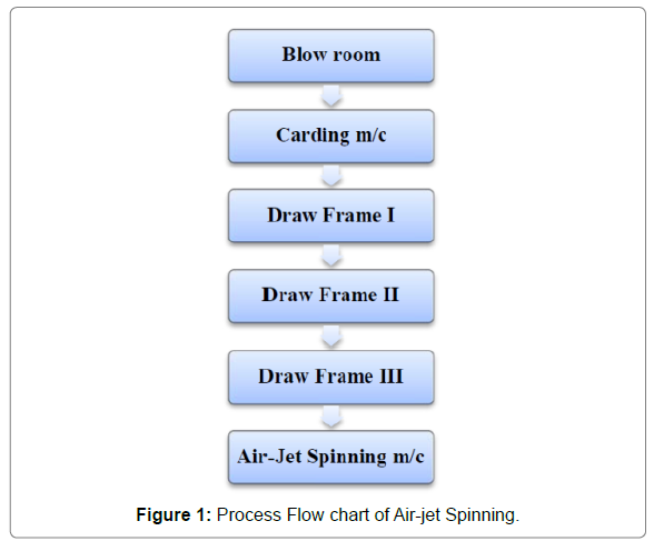
Objectives of air jet spinning: (1) To investigate the influence of process variables on yarn structure and yarn characteristics in air jet spinning. (2) To study the migratory behavior of fibres in air jet yarns by varying important process/machine parameters. (3) To predict the tenacity of blended air jet spun yarns by various models. (4) To study the surface properties such as friction, hairiness and abrasion of air jet spun yarns as a function of spinning parameters.(5) To compare the properties of air jet spun yarns made out of micro fibres vis-a-vis regular polyester fibres. (6) To study the low stress mechanical properties of weft knitted fabrics made out of ring and air jet spun polyester yarns. Although a considerable amount of work has been done on air jet spun yarns during the past twenty years or so, there are some areas where work is needed to have a better understanding of their structure and properties. Work on migration of fibres in air jet spun yams and production of yarns from microfibers is almost conspicuously absent in the published literature, on this subject. The present study therefore draws a special credence by its contribution to the available knowledge and research on this topic. (7) One of the proclaimed advantages of air jet spinning is the wide range of yam counts that can be spun on the machine and its potential for supplementing (or even supplanting) ring spinning, which has a considerably lower production rate. Because it is a relatively recent invention, there is a need to study the air jet spinning technology extensively to establish a “process-structure-property” relationship model to help engineer yams for specific end uses. It will be important to study and discuss the basic structural features of air jet spun yarn (Figure 1).
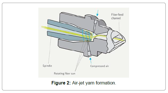
Basic Principle of Air-Jet Spinning: Sliver is fed into the machine and is further drawn out to the final count and twist is inserted by means of a rotating vortex of high pressured air. By the action of the vortex, the fiber ends eventually whirl around the spindle tip and are thus twisted around the twist less yarn core and transformed into a twisted yarn surface or cover fibers. This occurs at the spindle tip. Once inside the spindle tip, the yarn formation process is finished, and the yarn can be taken off and wound onto a package (Figure 2).
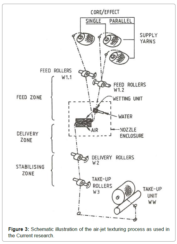
The Process: The requirements for air-jet texturing are illustrated schematically in (Figure 3). The process involves the ‘overfeed’ principle, whereby the multifilament supply yarn, provided ‘over end’ from a creel, is fed into the nozzle at a greater rate than it is taken away. To achieve this degree of overfeed, the yarn passes through the feed rollers Wl.l or W1.2 or both faster than it does through the delivery rollers W2. When the overfed filaments enter the nozzle, they are carried along through the nozzle, blown out from the texturing end, and formed into textured yarn by the effect of the air stream provided by a compressed-air supply. The zone between the feed rollers and the nozzle is termed the feed zone and the zone between the nozzle and the delivery rollers the delivery zone. The supply yarn is normally wetted just before it is fed into the texturing nozzle by passing it through a water bath or through a wetting unit, which can either be separate or integrated in the nozzle assembly (wet texturing apparently improves the quality of the yarn produced). Texturing nozzles are usually enclosed in a chamber, not only to reduce the noise created by the air-jet, but also to collect the used water and some of the spin finish washed away from the filaments during the process. Some texturing nozzles have an impact element at the nozzle exit, to be used optionally in certain cases recommended by the manufacturer. This can have one of several different shapes, i.e., cylindrical, flat, or spherical, as shown in the Hema Jet design in The element is believed to improve the process stability and yarn quality in the texturing of certain yarns. As well as a single supply yarn, two or more yarns of the same or different types can be textured at different speeds (core-and-effect texturing) by the use of separate feed rollers, Wl.l and W1.2. Another set of take-up rollers, W3, running at slightly higher speeds than the delivery rollers, W2, are used to apply tension to the textured yarn in order to stabilize the loops formed during the process, the zone between these two sets of rollers being termed the stabilizing zone. The textured yarn is then wound up by means of a high-speed take-up unit, WW. Heaters can be optionally used in the stabilizing and take-up zones to impart further desired properties to thermoplastic filament types.
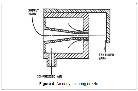
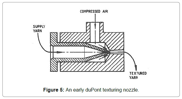
Industrial-nozzle developments: The air-jet texturing process spans three decades, and in that time it has seen many improvements in the process and many variations in nozzle design. The heart of the air-jet texturing process is the texturing nozzle. This may vary in design and details but remains unchanged in its underlying principles. (Figure 4) shows an example, the HemaJet, a typical industrial texturing nozzle. Piller1 claims that one of the earliest air-jet texturing nozzles, as shown in (Figure 4), was used on a standard ring-twisting machine in Czechoslovakia; the air emerging from the annulus entrains the yarn and blows it against a ‘bridge’ (an impact element), where the yarn is separated and formed into loops. However, it is doubtful whether the Czechoslovak jets were earlier than the rather similar nozzle (Figure 5) that was patented by du Pont2 in 1952. The best-known duPont Taslan Type 9 nozzle3 was introduced in 1954 and was used until the early 1970s. The Taslan process consisted in overfeeding the multifilaments into the nozzle by means of a’ stepped hollow needle inclined at 45° to the nozzle axis, the air entering axially as shown in (Figure 5). Normally, this nozzle was positioned with the nozzle axis in the vertical plane, but it is here shown in the horizontal plane so that its different yarn -feed and air-supply arrangements can be compared with those of the other nozzles illustrated.
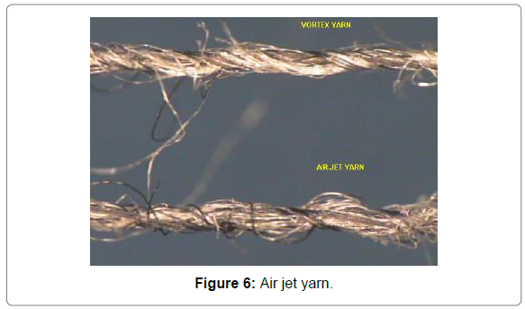
Structure of air jet spun yarn and vortex yarn: The unique structures associated with these yarns are a possible reason for the difference in yarn quality parameters. The higher tenacity values of vortex yarns can be attributed to the higher number of wrapper fibres in these yarns. The number of wrapper fibres is critical to yarn strength since they hold the internal parallel fibre bundle tightly together, and this effect is more critical for cotton fibres [2]. In air jet spinning, edge fibres ultimately produce wrapper fibres, and the number of edge fibres depends on the fibres at the outside [1,3]. On the other hand, in vortex spinning, the fibre separation from the bundle occurs everywhere in the entire outer periphery of the bundle [4]. This results in a higher number of wrapper fibres in the yarn. One possible explanation for the reduction in elongation is the decrease in fibre slippage due to better grip by wrapper fibres. Possibly the drop in hairiness values is another result of better wrapping (Figure 6).
Visual comparison of vortex and air-jet yarns showed that there were no apparent tendencies of cotton or polyester fibres to become either wrapper or core fibres in blended yarns [5]. Although this study did not provide enough information to reach a consistent conclusion, examination of these yarns under the microscope showed that vortex yarns have a more ring-like appearance as well as a higher number of wrapper fibres compared to air jet yarns.
Air flow in the chamber without yarn: Two air jets are supplied to the swirl chamber, namely:
1) the primary air jet – swirled, affected by four tangent nozzles that are supp-lied with compressed air of the press-ure equal to pn=0.7 MPa and the mass flow rate n=0.94·10-3 kg/s,
2) the secondary air jet – introduced to the chamber by the inlet channel which is used to deliver the raw material to the chamber; generated and affected by the primary swirled air jet; the mass flow rate of the secondary air jet is i=0.28·10-3 kg/s.
These jets are mixed in the swirl chamber in such a way that the swirled jet of the total mass flow rate, equal to =1.22·10-3 kg/s, flows through the swirl chamber. The outlet of the air from the chamber is free through the cylindrical part of the diameter d3>d2.
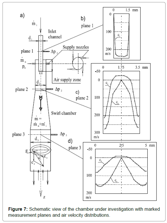
In order to visualise the flow in the chamber, distributions of air velocity components determined in measurement planes 1-3, denoted on the schematic view in (Figure 7a), are presented.
The measurements of air pressures and velocities inside the spinning chamber were of necessity made without the yarn being spun. This was caused by the small diameter of the chamber (d2=3.5 mm), which made it impossible to take direct measurements inside the chamber with a cylindrical one-hole probe. The relevant measurements were conducted in an enlarged model of the chamber (3:1) and recalculated into real conditions, employing the theory of flow similarity in swirl chambers described in an air velocity distribution in the inlet channel ci is shown. A considerable sub-atmospheric pressure in the neighborhood of the chamber axis causes the air jet to flow into the chamber at a significant velocity of 240 m/s. The swirl of the primary jet is not transferred to the secondary jet, and the velocity direction is consistent with the chamber axis (Figure 7b).
In (Figure 7c), distributions of air velocity components (circumferential cc and axial cz) in plane 2 are presented. The circumferential component distribution cc is typical of the forced vortex with the maximum at the wall and decreasing (approximately) linearly to the chamber axis (which is the most advantageous distribution from the viewpoint of the yarn transport). The distribution of the axial component cz indicates that a return flow of the air jet exists, which is characteristic of swirl flows, in the neighbourhood of the chamber axis. This indicates the high mixing intensity of the primary and secondary jets so that eventually there is a homogeneous, swirled jet of the mass flow rate at the end of the cylindrical part of the diameter d2. The value of the maximum resultant air velocity c at the wall is slightly higher than the sound velocity (1.06 Ma), which shows that the air in the supply nozzles reaches the sound velocity, and so the flow in this supply zone is supersonic [6].
In (Figure 7d), a distribution of the air velocity components (circumferential cc and axial cz) in plane 3 is given. Plane 3 is situated at the beginning of the cylindrical part of the diameter d3. A flow from plane 2 to plane 3 is typical of all swirl chambers, with a characteristic change in the profile and a value of the air velocity that follows from the restructuring of the enforced vortex into a free one [7].
Schematic view of the chamber under investigation with marked measurement planes and air velocity distributions; a) schematic view of the spinning chamber; b) air velocity distribution in the inlet channel, plane 1; c) air velocity distribution in the chamber, plane 2; d) air velocity distribution in the chamber, plane 3. Denotations: z – axis of the spinning chamber, g – distance of the measurement point from the spinning chamber wall, plane 1, plane 2, plane 3 – measurement planes, d1, d2, d3 – diameters of individual elements of the spinning chamber, Δp1, Δp2, Δp3 – air pressure on the spinning chamber walls in measurement planes 1, 2 and 3, pn – air pressure in supply nozzles, n – air mass flow rate supplied by supply nozzles, i – air mass flow rate supplied by the inlet channel, – total air mass flow rate, cc – circumferential component of the air velocity, cz – axial component of the air velocity, c– air velocity, ci – air velocity in the inlet channel [8-11] (Figure 7).
Air flow in the chamber during spinning: During spinning, the following measurements was conducted:
• Measurements and recording over time of air static pressures on the inner wall of the chamber, and
• Continuous measurements of the air volume flow rate supplied into the chamber by supply nozzles.
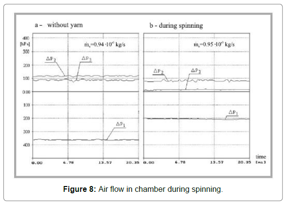
Air static pressures on the wall were measured in the measurement of planes 1 - 3 shown in (Figure 7), that is to say, Δp1 in plane 1 of the inlet channel, whereas Δp2 and Δp3 in planes 2 and 3 of the swirl chamber, correspondingly. In order to depict an influence of the yarn on the air flow, (Figure 8) shows the time functions of air static pressures on the wall and values of the mass flow rate n for the following variants:
a – without yarn,
b – during spinning.
During spinning, the mean values of the air sub-atmospheric pressure Δp1 in the inlet channel and of the air overpressure in the swirl chamber, both Δp2 in plane 2 and Δp3 in plane 3, decrease. The diagrams of air pressures vs. time maintain a similar character, i.e. a time-constant value of mean pressure and similar, slight pulsations. The air mass flow rate n during spinning did not exhibit any significant changes during spinning. A drop in sub-atmospheric pressure in the inlet channel and in pressures on the swirl chamber wall at the unaltered mass flow rate n allows us to state that:
• The yarn does not affect the flow in the supply zone (where the yarn is absent);
• The yarn mainly causes a decrease in the air circumferential velocity component cc in the swirl chamber;
• The decrease in the air velocity in the supply channel results from a decrease in the circumferential component in the chamber.
Based on the changes in the air sub-atmospheric pressure Δp1, it has been estimated that a decrease in the circumferential component of the velocity cc in the chamber and a decrease in the air velocity in the inlet channel are equal to 50%. The lack of any increase in air pressure pulsations and the fact that the time-constant values of mean values are maintained allows us to state that the yarn does not worsen the flow conditions of spinning, besides a significant change in the circumferential component of the air velocity cc. While comparing the air flow in the chamber under consideration to the flow in the variant with a forked inlet [12], it was found that the type of air inlet did not exert any significant influence on its parameters.
Twist direction of Air Jet Spinning:
The ability of the vortex to impart torque is so high that the turns of twist in the yarn run back to the drafting arrangement. The fiber strand is therefore accelerated practically to full rotation speed as soon as it leaves the front roller.
The edge fibers which ultimately bind the yarn together by becoming wrapping fibers are in a minority.
For process reasons, they do not exceed about 5% of the total yarn mass. These edge fibers exhibit relatively few turns of twist in the same direction as the false twisted core fibers or can even be slightly twisted in the opposite direction. This is partly ensured by causing the strand to emerge from the nip line in a broadly spread form, but mainly by generating in the first jet a vortex with an opposite direction of rotation to the vortex in the second jet.
This first vortex is in fact weaker in intensity than the second and cannot really affect the core fibers, but can grasp the edge fibers projecting from the strand at one end. Since the first vortex acts against the twist direction generated by the second jet, it prevents the edge fibers from being twisted into the core or even twists them in the opposite direction around the core fibers. As the strand runs through the second jet, the following occurs.
The turns of twist generated by the jet are canceled in accordance with the false twist law. The core fibers, i.e. the vast majority, no longer exhibit any twist; these fibers are arranged in parallel. On the other hand, the edge fibers (which previously exhibited no twist, relatively little twist, or even twist in the opposite direction) receive twist in the direction imparted by the jet, as determined by the law of false twist; they are therefore wound around the parallel fiber strand. They bind the body of fibers together and ensure coherence. A twist diagram prepared by Dr. H. Stalder demonstrates this twisting procedure [13].
The resulting bundled staple-fiber yarn passes from the take-off rollers through a yarn-suction device and an electronic yarn clearer before being wound onto a cross-wound package. The two nozzle air-jet spinning system represents a very interesting process, which has already been introduced into practical operation with some success.
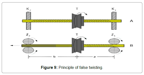
False Twisting: As the twist element is generating turns of S twist in the left hand section, this simply means that each turn of the Z twist imparted in the first section is canceled by a turn of S twist imparted in the second the fiber strand thus never has any twist between the twisting element and the delivery cylinder. In a false-twist assembly, turns of twist are present only between the feed cylinders and the twisting Element. This principle is exploited, for instance, in false-twist texturing (Figure 9).
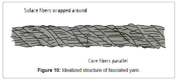
Fasciated Yarn through False Twisting: The idealized structure of the fascinated yarn, as shown in consists of parallel fibres held together by wrapper fibres. The wrapper and core fibres are composed of same staple fibre material. Since there is no real twist in the core, this type of yarn structures facilitates high production rates (Figure 10).
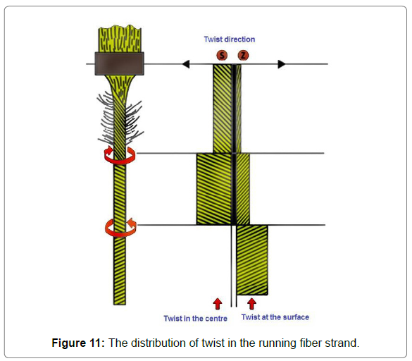
Demonstrates the principle involved in the production of fascinated yarn using the false twisting method. The ability of the vortex to impart torque is so high that the turns of twist in the yarn run back to the drafting arrangement. The fiber strand is therefore accelerated practically to full rotation speed as soon as it leaves the front roller. The edge fibers which ultimately bind the yarn together by becoming wrapping fibers are in a minority. For process reasons, they do not exceed about 5% of the total yarn mass [14-16].
These edge fibers exhibit relatively few turns of twist in the same direction as the false-twisted core fibers or can even be slightly twisted in the opposite direction. This is partly ensured by causing the strand to emerge from the nip line in a broadly spread form, but mainly by generating in the first jet. A vortex with an opposite direction of rotation to the vortex in the second jet. This first vortex is in fact weaker in intensity than the second and cannot really affect the core fibers, but can grasp the edge fibers projecting from the strand at one end. Since the first vortex acts against the twist direction generated by the second jet, it prevents the edge fibers from being twisted into the core or even twists them in the opposite direction around the core fibers. As the strand runs through the second jet, the following occurs. The turns of twist generated by the jet are canceled in accordance with the false-twist law. The core fibers, i.e. the vast majority, no longer exhibit any twist; these fibers are arranged in parallel. On the other hand, the edge fibers (which previously exhibited no twist, relatively little twist, or even twist in the opposite direction) receive twist in the direction imparted by the jet as determined by the law of false twist; they are therefore wound around the parallel fiber strand. They bind the body of fibers together and ensure coherence. A twist diagram prepared by Dr. H. Stalder demonstrates this twisting procedure (Figure 11).
The resulting bundled staple-fiber yarn passes from the take-off rollers through a yarn-suction device and an electronic yarn clearer before being wound onto a cross-wound package. The two nozzle air-jet spinning system represents a very interesting process, which has already been introduced into practical operation with some success.
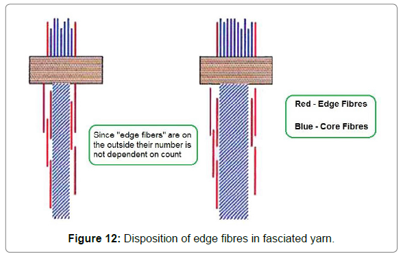
Yarn strength: The tenacity of the fascinated yarns spun with air jet depend on the yarn count. The coarser yarns are weaker than the finer yarns for the same fibre type. Contrary to the expectation, yarns produced with finer fibres show lower tenacity compared to the yarns produced with coarser fibres. The reason for the above observations is that the strength of the fascinated yarns is derived from the amount of wrapper fibres and the intensity of wrapping. The edge fibres are the ones which ultimately get converted into wrapper fibres. The number of edge fibres is limited to the surface of the yarn and are independent of the number of fibres in the core as shown in (Figure 12).
Hairiness, Abrasion and Wear Resistance: Compared to yarn spun using other spinning processes, air jet- spun yarn displays the lowest hairiness. The spinning process and the yarn structure obtained as a result create new, complementary possibilities in downstream processing of the yarn. The advantages of low hairiness range from cost savings in the knitting process to unique advantages in the textile product in terms of abrasion, wear resistance, pilling and wash fastness. Yarn abrasion is directly related to yarn hairiness and the integration of the fibers in the yarn strand. One advantage of air-jet-spun yarn is clearly apparent: Lower abrasion will result in significantly less soiling and less fiber fly during downstream yarn processing, thereby extending cleaning intervals on the machines. The abrasion resistance of the yarns is a further important criterion in subsequent downstream yarn-processing stages and the yarn’s serviceability properties in the textile fabric [17-19].
Automation: As mentioned above, the J 20 is equipped with four robots, with two on each side of the machine. In addition to cleaning the spinning position and automatically piecing the yarn after a thread break or a clearer cut, the robot changes full bobbins and threads up the empty tubes. It also features a fan that cleans fiberfly from the spinning positions. The robot is based on rotor-spinning automation technology. The entire piecing process is electronically controlled. The machine is designed so that both machine sides are optionally entirely independent of each other.
Blends: The duo-spinning unit expands the J 20’s field of application, and it can process viscose, Modal® and blends of these fibers with cotton. Ideally, a somewhat coarser and shorter cotton fiber can be chosen for raw material blends on economic grounds. A corresponding reduction in noil can be achieved when combed cotton is used.
During development of the machine, care was taken to enable as many fiber materials as possible to be processed using the same top roller cots.
Drafting: The drafting arrangement technology adopted for the air-jet spinning machine has been adapted to high speeds. In order to achieve the extremely high drafts, the 3-over-3 drafting arrangement was further developed to a 4-over-4 arrangement, allowing a gentle fiber drafting in three stages.
The robust arrangement features a unique, patented traversing system. The feed sliver and the yarn produced as a result are laterally traversed — thus extending the lifecycle of the top rollers, cots and aprons threefold, which considerably reduces long-term maintenance and spare parts costs and ensures consistent yarn quality over time, Rieter reports.
Lower Energy, Space Needs: For most applications, Rieter claims that the air-jet spinning technology consumes less energy per kilogram of produced yarn than other spinning processes. Shutdown of individual spinning units thereby pays off. During development, the dimensions of the J 20 were also considered, to ensure that the machine could be installed in existing spinning rooms.
Space needs for the J 20 are 25-percent less than for ring-spinning equipment producing the same capacity, thereby reducing building costs. Also, the smaller area requires less climate control, resulting in further substantial savings.
New Markets: The new air-jet spinning technology produces new yarns with new yarn characteristics, and opens new market opportunities for spinning plants. Yarn formation is achieved by turbulence with airflow in a spinning nozzle, which creates a quite different yarn structure. Yarn produced by the J 20 is marketed under the Comfor Jet® brand. Since ITMA 2011, Rieter has begun marketing the J 20 worldwide. The company claims that “the J 20 is a production miracle with smallest space requirements. With its high operating speed of up to 450 m/min and 120 spinning units, the J 20 air-spinning machine heads the productivity scale.”This technology is certainly an attractive alternative to all other existing spinning processes. However, its market acceptance will show if this assessment is true.
Yarn Characteristics of Air-Jet Spin Yarn
The yarn character is slightly different from that of ring spun yarn. It is somewhat: weaker, stiffer, and harder.
Positive:
• Good evenness (like ring-spun yarn);
• Good abrasion resistance;
• Low tendency to pilling;
• Low snarling tendency;
• Shrinkage similar to that of ring-spun yarn;
Negative:
• Higher resistance to bending;
• Slightly lower covering power;
• Wrapping fibers not uniformly distributed over the length; sometimes there are slightly more on the surface, sometimes slightly fewer.
• A large number of wrapping turns impart more strength but at the same time greater hardness. Synthetic fiber yarns and blends of synthetic fibers and cotton with a proportion of synthetic fibers of at least 50% achieve strength levels of about 80% or more relative to ring-spun yarn.
Advantages of Air-jet Spinning
• Creates functional & fashionable yarn
• Integration of three processes; roving, spinning & winding by the MJS
• Integration of four processes; roving, spinning, winding & doubling by the MTS
• User-friendly in operation management
• The spinning speed of 340m/min
• User-friendly in quality control
• Totally saves space, labor & energy
Advantages of Air-jet Yarns
• Less hariness & Clear appearance
• High resistance to Pilling & abrasion
• High moisture absorption
• Less shrinkage & High wash resistance
• Can be spun with various other materials such as cotton, synthetic fiber, regenerated fiber and blended fiber.
• Yarn structure also suitable as core yarn.
Conclusion
In this study, the effect of plying process parameters on Rieter air-jet yarn properties is investigated. It is obvious that both ply twist value and twist direction influence plied air-jet yarn properties. Plying in the same direction of the single yarn wrapper fibres twist direction improves hairiness, while plying in the opposite direction of the single yarn wrapper fibres twist reduces snarling twist tendency and improves yarn tenacity. Results show that increasing ply twist improves yarn abrasion resistance and hairiness.
As the most important and unexpected finding is the significant effect of twist direction on yarn mass irregularity as well as number of neps. The reason of higher values of yarn mass irregularity and number of neps of plied yarns twisted in the opposite direction of single yarn wrapper fibres can be attributed to their marked deterioration in geometrical structure of wrapper layers due to opening of wrapper fibres and creation of new random irregular structure.
References
- Krthekeyan S, Kathrivel M & Chellamani K (1995) Proceedings, International Conference on Recent Advances in Spinning Technology (The Bombay Textile Research Association, Bombay): 10.
- Tygai G, Patnik A, Goyal A, Salhora K & Ishtiaque S (2002) Indian J Fibre Text Res 27: 236.
- Kazimierski Z, Zawadzki L (1974) Similarity of swirling incompressible flows in vortex tubes (in Polish); Technical University of Łódź, Scientific Bulletin no. 235.
- Grosberg P, Oxenham W, Miao M (1987) Insertion of ‘twist’ into yarns by means of air jets. I. An experimental study of air-jet spinning. II. Twist distribution and twist insertion rates in air-jet twisting. J Text Inst 78: 189- 219.
- Miao M, Oxenham W, Grosberg P (1988) Yarn formation in a pneumatic system. Przegląd Włókienniczy 1988: 360-364.
- Nakahara T (1988) Air-jet Spinning Technology. Text Tech Int: 73-74.
- Miao M, Chen R (1993) Yarn twisting dynamics. Text Res J 63: 150-158.
- Klein W (1993) New spinning systems, short-staple spinning series. Tex Inst 5: 40-41.
- Oxenham W, Basu A (1993) Effect of Jet Design on the Properties of Air-jet Spun Yarns. J Text Res 63: 674-678.
- Kowalczyk L, Kubica H, Gaca T (1994) Influence of the spinning speed on the quality of the yarn formed with the pneumatic false-twist method. Przegląd Włókienniczy, Łódź 1994: 2.
- Dodd E, Oxenham W (2000) Open end vs. ring-spun pricing. Ame Text Ind 29: 118-120.
- Golański J, Witczak D. Air flow and an influence of fibres and the yarn on selected parameters in the overpressure spinning chamber. Reports of the Textile Research Institute: 49.
- Jóźwicki R (2002) Mechanism of formation and tensile properties of the yarn made with a new spindleless spinning method (in Polish). Tex Res Inst: XLIX.
- Basal G, Oxenham W (2003) Vortex spun yarn vs. air-jet spun yarn. Autex Res J 3: 96-101.
- Kaushik R C D, Salhotra K R, Tyagi G K (1989) Influence of extension rate and specimen length on tenacity and breaking extension of acrylic/viscose rayon rotor spun yarns. Text Res J 59: 97-100.
- Hearle J W S, Thakur V M (1961) The Breakage of Twisted Yarns. J Text Inst Trans 52: T49-T63.
- Realff M L, Seo M, Boyce M C, Schwartz P, Backer S (1991) Mechanical properties of fabrics woven from yarns produced by different spinning technologies: yarn failure as a function of gauge length. Text Res J 61: 517- 530.
- Oxenham W, Zhu R Y, Leaf G A V (1992) Observations on the tensile properties of friction-spun yarns 83: 621-623.
- Peirce F T (1926) Tensile tests for cotton yarns: “the weakest link” theorems on the strength of long and of composite specimens. J Text Inst 17: 355-368.
 Spanish
  Chinese
  Russian
  German
  French
  Japanese
  Portuguese
  Hindi
Hindi 