Spanish
  Chinese
  Russian
  German
  French
  Japanese
  Portuguese
  Hindi
Hindi Short Communication, J Ind Electron Appl Vol: 1 Issue: 1
Protection Coordination of Biogas Power Plant Connected to Distribution Network
Tomislav Vukasovic1, Srete Nikolovski1*, Dragan Mlakic2 and Dean Vucinic3
1Department of Power Engineering, University of Osijek , Osijek, Croatia
2Mostar, Bosnia and Herzegovina
3Vesalius College, Vrije University, Brussel, Belgium
*Corresponding Author : Srete Nikolovski
Department of Power Engineering, University of Osijek, Osijek, Croatia
Tel: 385 31 224 600
Fax: 385 31 224 6005
E-mail: srete@etfos.hr
Received: November 30, 2017 Accepted: December 01, 2017 Published: December 10, 2017
Citation: Vukasovic T, Nikolovski S, Mlakic D, Vucinic D (2017) Protection Coordination of Biogas Power Plant Connected to Distribution Network. J Ind Electron Appl 1:1.
Abstract
Over the past few decades, the need for proper protection coordination at the distribution level has increased due to the addition of distributed generation (DG) to radial distribution networks. In radial distribution networks the problem of coordination of overcurrent protection (OCP) devices does not exist- The relay, which is located at the furthest point from the source, is tripped in the shortest time. Other relays are tripped in a sequence with longer time delays, going back in the direction of the source. The paper presents the integration of the biogas (BG) power plant with the rated power of 1 MW to the Croatian distribution network. During the integration process the most important part on which the Croatian HEP Distribution System Operator (DSO) insists is the study of protection coordination. The protection coordination, and the antiisland protection, plays a significant role in the process of DG connection to the distribution network. The distributed generations from any type of renewable (PV, wind, biogas or biomass) power plant is not allowed to work in island with DSO in Croatia. Also the existing Network Grid Code does not allow islanding work too. This paper presents a protection coordination model of all the passive protection devices used in the real biogas power plant connected to the distribution network. The short-circuit currents for 3 phase fault (LLL) and single line to ground faults (SLGF) in the BG power plant and the surrounding distribution network are modelled and simulated. The protective devices are modelled with their real current-time characteristics. The protection coordination is performed using the SmartPDC-Smart Protective Device Coordination modules of the Easy Power Protector Software tool.
Keywords: Biogas power plant; Distribution network; Short circuits; Protection devices; Protection coordination; Modelling and simulatio
Introduction
The short circuits are unwanted events within the power system, not easy to predict, resulting from a variety of adverse operating conditions of generators, transformers, lines or generated from the entire transmission systems. While impossible to predict their occurrence, their presence brings the system in the worst possible state. Thus, it is important to determine the amount of current created by each type of fault, and at any point, in the system. With the advancement of the distribution systems, new methods and software tools for calculation of the short circuit currents are being developed taking into account any parts of the system, and their respective contribution to the fault currents of individual system units. In the worst cases, the amounts of the short circuits, take into account several thousand amperes, which often increases to tens of kA. Today, the computer applications, for example, EasyPower, DIgSILENT, ETAP, NEPLAN, PowerWorld, can in a few seconds, after the input data about network are provided, show the current amount of fault currents in any specific part of network. As such, these programs have largely replaced the hand calculations, and thus, shorten the time of calculation and removed the human errors in calculation.
With the distributed generation and more power plants, which are fuelled by the renewable energy sources, rise up the problem of protection in such distribution systems, because the existing hedge no longer fulfil the criteria of the amount of short circuit current. By installing any type of power plant or energy insertion in network, the consumer needs to change its structure, from the passive consumer to the active consumer/prosumer, and thus it becomes evident that there is a bi-directional short circuit current flow. Several authors have addressed various OCP studies for radial distribution systems. [1-3]. some authors, in [4-6], provided OCP schemes using example radial systems with distribution generation. In [7], authors discuss integration of solar power plant in distribution network, and OCP devices coordination using Time-current curves (TCC) and time domain simulation of faults currents.
Biogas Power Plant
Technical data about power plant
The BG power plant is built in Crnac, a village located in the Virovitica-Podravina County, within a project in which the “Bionardo” company has made an investment. The BG plant is a cogeneration type, where, in addition to the electricity production uses the thermal energy released by the combustion engine, which is used for heating the mass of the digesters. The green mass used in this plant is purchased from the producers of local cornpost and sorghum silage. The aerial view of the BG power plant is shown in Figure 1. In addition to the nominal data transformer and the generator protection settings, an authorized access to enter into the power plant was needed, to be able to obtained adequate data. For the production of 1 MW of the electrical power it is required that every half hour 1.2 t of silage is available, which results in the requirement of 57.6 t silage per day.

Figure 1: Location of biogas power plant “crnac”.
The BG plant is a cogeneration plant, in which, besides the electricity, the thermal energy is used for its own specific purposes. The raw material, from which the biogas is generated, is the silage corn and the sorghum silage. The principle of obtaining biogas is following: The mixer is supplied with the green mass, which is mixed with water. This mass is stirred, and later on goes into the digester, where it is heated. The digester is a proctor, in which, under the anaerobic conditions the products, as biogas and digestate are obtained. The biogas is combusted in the engine that drives an electric generator. Within the engine room, there is a cogeneration unit GE Jenbacher Type JMS 320 GS to which shaft the Stanford synchronous generator is connected. The engine and the entire plant are shown in Figure 2.

Figure 2: View of the biogas plant.
The management of this facility requires a person, who is placed in the control room and supervises the entire plant. The operations carried out by the manager are: dosing green mass, control of gas in the tank, the control of generator operation and all parts of the plant. This process model is automated in SCADA system.
Grid connection criteria
The Network Grid Code [8] govern the operation and management, development and construction of the power system and the establishment of transmission and distribution network in the electric power system and metering rules throughout the accounting points of energy share. The purpose, of the technical and operating requirements for its connection to the distribution network, is to ensure normal operation of the distribution network, in order to prevent damage effects on the network and its users. The special and additional technical and operational conditions will take into account the specific operation and technical characteristics of the production units. The connection point of the distributed source voltage level and its operating conditions are determined by the DSO operator rulers, and in accordance with the general conditions for the electricity supply and network policies [9]. The power plants that are connected to the distribution network, following the network rules, are divided into the following categories [9]. According to the nominal connection:
• Connected to LV network
• Connected to MV network and according to the nominal power plant
• Micro power plants with power to 30 kW,
• Power plants of less than or equal 5 MW
• Power plants exceeding 5 MW.
On the medium voltage network (10, 20, 35 kV), the power plants exceeding the 500 kW up to and including 10 MW are connected, but there can be also connected the power plant with less energy production. The power plants up to 500 kW are connected to the lowvoltage network. However, they can be connected to the low voltage line or low voltage transformer stations 10 (20)/0.4 kV. The power plants up to 100 kW are connected to the low voltage network [5] (Table 1).
| Manufacturer | Stanford | |
|---|---|---|
| Power | kVA | 1445 |
| Power at cos f=0.8 | kW | 1156 |
| Rated current | A | 2085.7 |
| Frequency | Hz | 50 |
| Rated voltage | V | 400 |
| number of poles | 4 | |
| RPM | 0/min | 1500 |
| Permitted speed | 0/min | 2250 |
| Permitted cos f | 0.8-1.0 | |
| Efficiency at cos f=1 | % | 97.1 |
| Effectiveness at cos f=0.8 | % | 96 |
| Moment of inertia | kgm2 | 36.33 |
| Model | B3/B14 | |
| Mechanical protection | IP 23 | |
| Insulation class | H | |
| The maximum permissible ambient temperature | oC | 40 |
| Total harmonic distortion – THD | % | 1.5 |
| Direct reactance | p.u. | 2.51 |
| Subtransient reactance | p.u. | 0.11 |
| Transient reactance | p.u. | 0.15 |
| The time constant of the subtransient | ms | 10 |
| Constant direct time | ms | 20 |
| Open circuit time constant | s | 2.23 |
Table 1: Distribution according to histological subtype (Stanford Generator unit technical data).
Short Circuits and Protection Coordination
Three-phase short circuit
When the computer model of the power plant and surrounding network has to be created, it is important to model a true topological state of the network. The existing of the distributed sources creates the problem of double-fed faults. With that in the mind, when approximating the surrounding network, the most important is to take into account the place of the power plant in respect to the upper HV network, and to model it accurately as possible. The OCP devices and their characteristic uses time delay to provide tripping. There are several types of OCP relays characteristics which are classified based on their Time current curves (TCC). IEC 60255 standards defines a number of standard characteristics as follows [10]:
Standard Inverse (SI) t=TMS * k /[(If / Is)0.02 -1] (1)
Very Inverse (VI) t=TMS * k /[(If / Is) -1] (2)
Extreme Inverse (EI) t=TMS * k /[(If / Is)2 -1] (3)
Long Time Inverse (LTI) t=TMS * k /[(If / Is) -1] (4)
Where:
TSM: the time multiplier setting; If: the relay overload or fault current; Is: the pickup current of relay; k: constants which depend on the relay characteristics (0.14, 13.5, 80 and 120) (Table 2).
| Manufacturer | Koncar |
|---|---|
| Transformer rated power [SN] | 1250 kVA |
| Rated voltage: | 10(20)/0.4 kV |
| Short circuit voltage u k % | 6% |
| Copper losses PCu | 10 kW |
| Iron losses PFe | 1,2 kW |
| Short circuit loses i0 | 0.4% |
| Type of compound | Dyn5 |
| Type of cooling | ONAN |
Table 2: Unit transformer data (Transformer technical data).
The model of the biogas plant and the surrounding distribution network are shown in Figure 3 [11]. The studied coordination of the overcurrent protection path propagates from the substation ČaÄÂinci 35/10(20) kV to the feeder VP Crnac, in order to meet the power plant, where it connects to the network. The protective devices, relays, together with the associated current measuring transformers (CMT) and the high voltage and low voltage circuit breakers switch are located on the bus, starting immediately after the power plant generator, as shown in Figure 3, where they are denoted respectively BL-1, R-1, R-4 and R-5. Three-phase short-circuit (LLL) is type of fault, which in a normal operation happens very rarely, but because of the large amount of currents that can occur, if with this type of faults arise, it is very important to calculate three-phase short circuit. After successfully completing the load flow analysis, the Short Circuit is performed by activating the three-phase short circuit. The obtained results are presented in Tables 3 and 4 for the whole observed network

Figure 3: Network model and short circuits in the area of the plant BIONARDO.
| 3 Phase Fault | Total Fault Currents | ||
|---|---|---|---|
| Bus Name | Bus (kV) | Sym (A) | Asym (A) |
| BIONARDO_10KV | 10.0 | 980.2 | 1015.7 |
| CRNAC1 | 10.0 | 888.0 | 908.3 |
| CRNAC2 | 35.0 | 281.3 | 291.0 |
| CRNAC2_0.4 | 10.0 | 136.8 | 144.6 |
| K-L | 10.0 | 1597.2 | 1624.6 |
| L-K | 10.0 | 3037.0 | 3667.5 |
| PAUŠINCI | 10.0 | 1469.2 | 1487.6 |
| RASTOVAC | 10.0 | 1271.9 | 1290.6 |
| RASTOVAC2 | 10.0 | 901.9 | 904.5 |
| S.P.POLJE | 10.0 | 1073.1 | 1081.7 |
| SLATINA2_35KV | 35.0 | 5750.3 | 8120.8 |
| SLATINA2_110KV | 110.0 | 9163.2 | 10087.2 |
| SUSRETNO | 10.0 | 984.8 | 1019.0 |
| VP_SLATINA1_10KV | 10.0 | 6450.1 | 9490.1 |
| VP_SLATINA1_35KV | 35.0 | 5517.9 | 7592.1 |
| VP_CACINCI_10KV | 10.0 | 3047.3 | 3686.7 |
| VP_CACINCI_35KV | 35.0 | 1841.6 | 2005.2 |
Table 3: High voltage momentary short circuit report.
| 3 Phase Fault | Total Fault Currents | ||
|---|---|---|---|
| Bus Name | Bus (kV) | Sym (A) | Asym (A) |
| BIONARDO_0.4KV | 0.4 | 26353.8 | 30660.8 |
| CRNAC1_0.4 | 0.4 | 12278.7 | 13254.2 |
| KRIVAJA_0.4 | 0.4 | 8979.1 | 10023.1 |
| PAUŠINCI_0.4 | 0.4 | 7921.5 | 8788.1 |
| RASTOVAC2_0.4 | 0.4 | 14382.1 | 14784.9 |
| RASTOVAC_0.4 | 0.4 | 9854.9 | 10895.1 |
| S.P.POLJE_0.4 | 0.4 | 7616.5 | 8289.7 |
Table 4: Low voltage momentary short circuit report.
For the relays R-1 and R-4, CMT with tap ratio 50/5 A are selected, while for the relay R-5, CMT with tap ratio level 60/5 A is selected. All the relays are Siemens 7SJ63 model, while the LV breaker is Siemens Molded Case Circuit Breaker (MCCB) type. Once being selected, CMT’s relays and low voltage breaker, it is necessary to adjust the relays and electrical values for the currents. Each of these elements has more degrees of protection, but for setting the low voltage breaker the following information is proposed:
The rated current of the generator, and the data from the nameplate, is 2085, 7 A. Therefore, the first level of protection, thus, the generator protection against overload is set at a slightly higher value, on average 10% higher than the nominal, and with having longer time delays. The second level of protection is adjusted to the minimum value of the short circuit current and the third level, as a quick stage, in which the current value is twice the maximum of the short circuit current. The overload protection must be able to detect the internal faults at 10 kV customer switchboards, and act as a backup protection for 10/0.4 kV. The first stage of overcurrent protection should be set to prevent the overloading of the generator or to eliminate the excessive injection of the active and reactive power back to the network [8]. Therefore, the first step of the relay R-1 can be set to:
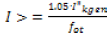 (5)
(5)
Where:
Ikgem: rated generator current calculated for 10 kV
fot: release factor (for digital relay 0.95)
1.05: reserve factor
The second stage overcurrent protection should be set above the value of the current flowing in the field of separation, in the case of three-phase short circuit at the generator busbars. According to the performed calculations, it results in 450 A. Therefore, the setting of the second stage overcurrent protection is done according to the equation:
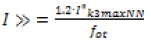 (5)
(5)
When setting the overcurrent protection in 35/10 (20) kV ČaÄÂinci, the supplying feeder VP Crnac, for the first stage overcurrent protection is set to maximum load in the network and end users. It is compliant with the lowest current two-phase short circuit and current setting of I>180 A, having the time delay of 9.3 s, which is selective and does not require to be changed. The highest maximum short circuit current with the contribution of the power plant, in the case of the close short circuit, is 3050 A. It is necessary to determine the second stage of the overcurrent protection relay R-5 according to the expression:
The final proposal for the protection relays setting is defined in the following tables:
After calculating the current tripping relays and the time delay, data from 2, 3, 4 and 5 have been included in the Easy power program, in that respective order [11,12]. When all the required data are entered, in the EasyPower tools bar, the Power protector module is activated and respectively denotes the protection devices BL-1, R-1, R-4 and R-5, assuming that we properly calculate the current tripping relays and the time delay, and further on, the protection devices should be selectivity achieved
For the first fault (in SC 1) the three-phase short circuit at the generator bus of the BG plant is taken. The amount of the threephase short circuit current is 26.35 kA and most of the contribution is resulting from the power plant. It is common that the low-voltage side of the transformer does not have the overload protection device, thus for tripping the low voltage breaker BL-1 is charged. To check, whether indeed, the low voltage breaker has to turn off this fault current, as shown in Figure 4, 5. The only protection device, which is on the low voltage side, is the breaker BL-1, which is shown as the purple-hatched graph in Figure 6., because in practice, the LV side of the transformer does not put overload protection device. The breaker will be deactivated at the time of 100 ms (Table 5).

Figure 4: Overcurrent protection coordination for SC1.

Figure 5: Overcurrent protection coordination for SC2.
| LV breaker BL-1 | ||||
|---|---|---|---|---|
| Breaker type | Protection | Protection setting | ||
| Current [kA] | Time [s] | |||
| Siemens MCCB | Generator overload protection | 3I> | 2,25 | 20 |
| Generator multiphase protection SC(1) | 3I>> | 7,875 | 0.1 | |
| Generator multiphase protection SC(2) | 3I>>> | 35 | 0.05 | |
Table 5: The proposed setting for LV breaker BL-1.
The next place of fault (SC2) is on the high voltage side of the transformer station BP plant. At the point of fault 2, it is shown that through the HV side of the transformer station BG plant is flowing fault current of 450 A, and from the network fault current amount is 620 A, and it is shown in Figure 6 (Tables 6-9).

Figure 6: Overcurrent protection coordination of SLGF for SC2.
| Relay R-1 | ||||
|---|---|---|---|---|
| Model | Protection | Protection setting | ||
| Current (A) | Time (s) | |||
| Siemens 7SJ63 | Overload protection | 3I> | 89 | 10 |
| Multiphase SC protection | 3I>> | 400 | 0.2 | |
Table 6: Proposal for setting protection relay R-1.
| Relay R-4 | ||||
|---|---|---|---|---|
| Model | Protection | Protection setting | ||
| Current (A) | Time (s) | |||
| Siemens 7SJ63 |
Overload protection | 3I> | 90 | 15 |
| Multiphase SC protection | 3I>> | 499.3 | 0.25 | |
Table 7: Proposal for setting protection relay R-4.
| Relay R-5 | ||||
|---|---|---|---|---|
| Model | Protection | Protection setting | ||
| Current (A) | Time (s) | |||
| Siemens 7SJ63 | Overload protection | 3I> | 180 | 9.3 |
| Multiphase SC protection | 3I>> | 703.2 | 0.31 | |
Table 8: Proposal for setting protection relay R-5.
| Model | Protection | Protection setting | ||
|---|---|---|---|---|
| Voltage (kV) | Time (s) | |||
| Siemens 7SJ63 | Over voltage | U> | 11.1 | 60 |
| Over voltage | U>> | 11.5 | 0.5 | |
| Under Voltage | U< | 9 | 1 | |
| Under Voltage | U<< | 8 | 5 | |
| Over frequency | f> | 50.6 Hz | 1 | |
| Over frequency | f>> | 51.5 Hz | 0,5 | |
| Under frequency | f< | 49 Hz | 1 | |
| Under frequency | f<< | 48 Hz | 0.5 | |
| Generator | ||||
| Siemens WLII 2500 N |
Over voltage | U> | 11.1 | 2.4 |
| Over voltage | U>> | 11.5 | 0.1 | |
| Under Voltage | U< | 9 | 2.4 | |
| Under Voltage | U<< | 8 | 0.1 | |
| Over frequency | f>> | 51.5 Hz | 0.1 | |
| Under frequency | f< | 49 Hz | 0.5 | |
| Under frequency | f<< | 48 Hz | 0,1 | |
| Phase shift | T> | 9 o | 0.0 | |
Table 9: Proposed protection settings of anti-islanding protection for power plant.
Through CMT relay R-1 current flows coming from the generator, this current is taken as a reference fault current: It can be seen that the first switch off is on relay R-1 during the period of 200 ms. In case that relay R-1 fails to trip, the next relay that is behind it, is the relay R-4, which will wait to set time of 250 ms and switch off. In the worst case scenario, if both relays fail (R-1 and R-4), the relay R-5 will wait with its time delay and then switch off. If in this case there is a failure of the relay R-1 and R-4 and up and running relay R-5, with its tripping in a time of 310 ms, the entire feeder line from ČaÄÂinci MV 35/10 (20) kV will be switch off. The next place for fault (SC3) is at substation facilities that is almost identical fault current through the lines, with the current flowing from the generator to the fault is 440 A, while from the network flows the same amount of fault current, 620 A. For this case, the three-phase short circuit current at a particular position of fault will work through the first relay R-4 after 250 ms and so switch off the line to the plant. In case of failure tripping relay R-4, its backup relay R-5, will switch off for 300 ms and thus will switch off the entire feeder line from TS ČaÄÂinci MV 35/10(20) kV and interrupt the supply of the electricity to all the consumers in the area.
Single line to ground fault
In case of Single Line to Ground Fault (SLGF) is in place SC2 at buses neighbouring plant generator contributes to the current fault of 670 A and network current of 470A. Accordingly, the tripping will be at the first generator fault, which will, switch off the relay R1 after 100 ms and then the relay R4 after 300ms. If it fails to trip, the fault by the network switches off relay R5 will be activated with the time delay of 600 ms. this is shown in Figure 6.
For SLGF on the line near MV buses kV ČaÄÂinci, at the junction of overhead and cable lines contribution from the generator in a stream SLGF is 300 A and the contribution of the network is 450 A. The diagram shows that the previous adjustments of relay R5 for SLGF is from 520 A, thus to high and relay R5 will not detect it, in order to switch off that fault. The generator would be disconnected from the network tripping by the relay R1 within the time period of 100 ms. Therefore, it is necessary to set the protection of SLGF at value I>>420 A in order to detect the currents of 450A and switch of SLGF. This situation is shown in Figure 7.

Figure 7: Overcurrent protection coordination of SLGF for SC3.
In addition to the coordination overload protection to meet the plant, there are passive safety features designed to protect the islanding of the power station. Their settings are shown in Table 8.
Conclusion
With the development of the distributed energy sources, the false tripping of the existing protection may occur in the network. If a fault occurs anywhere in the network, faults will be fed from the 2 sides: (1) from the grid and (2) from the distributed generators. It is of great importance to perform the short circuit calculations and correctly make protection coordination for all devices on the existing network with distributed generators. In this paper, the biogas power plant BIONARDO is modelled with the surrounding network and the real time settings with the objective to coordinate the overcurrent protection relays that have been installed in the network. The calculation is performed for the LLL and SLG faults, at the plant, with the primary side of transformer, taking into account the facility and location, which is near the power supply point substation 10 kV ČaÄÂinci. This has been followed up with the time-current settings of all the degrees of protection, and performed for all the relays. From the analysis of the data obtained, it can be concluded that the proposed setup is correct for the LLL faults, but has to be further investigated (checked and corrected selectivity) for the SLG faults on relay R5.
Acknowledgement
The authors want to thanks to the management of biogas power plant Crnac for their permissions to visit and use their proprietary data in this paper.
References
- Birla D, Maheshwari RP, Gupta HO (2005) Time-overcurrent relay coordination: A review. International Journal of Emerging Electrical Power System 2: 1039
- Funmilayo HB, SilvaJA,Butler-Purry K (2012) Overcurrent protection for the IEEE 34-node radial test feeder. IEEE Trans Power Deliv 27: 459-468.
- Zellagul M, Changal A (2014) Impact of RDG location on IDMT overcurrent relay operation and coordination in MV distribution system. Indonesian Journal of Electrical Engineering 12: 7585-7594.
- Zamani A, Sidhu T, Yazdani A (2010) A strategy for protection coordination in radial distribution networks with distributed generators. IEEE Power and Energy Society General Meeting 10: 263-270.
- Fardanesh N, Richards E (1984) Distribution system protection with decentralized generation introduced into the system. IEEE Transaction on Industrial Application 20: 122-130.
- Gomez J, Morcos M (2005) Coordination of voltage sag and overcurrent protection in DG systems. IEEE Trans Power Delivery 20: 214-218.
- Nikolovski S, Maric P, Majdandžic L (2015) Integration of solar power plant in distribution network. International Journal of Electrical and Computer Engineering 5: 656-668.
- Rural Maintenance (Pvt) Ltd. (2006) General conditions for electric power supply.
- Croatian distribution company HEP-DSO (2008) Instructions of applying actual laws and rules for connection of RES and cogeneration on distribution and transmission.
- AREVA T&D Automation & Information Systems Network protection and automation guide (2005) Overcurrent protection for phase and earth faults, pp: 122-151.
- Elaborate of optimal connection on electrical network biogas power plant Crnac (1000 kW) (2012) Koncar electrical engineering institute.
- EasyPower® Electrical Software (2016) EasyPower 9.8. User’s manual. Oregon, USA.