Spanish
  Chinese
  Russian
  German
  French
  Japanese
  Portuguese
  Hindi
Hindi Research Article, J Fashion Technol Textile Eng Vol: 5 Issue: 2
Research on the Modeling Method for Digital Weaving Based on the Information of Physical Yarns and Fabric Pattern
Ping Zhong*, Zaifeng Shi, Meng Jiang, Fu Yang, Hao Zheng and Bo Yang
Department of Applied Physics and State Key Laboratory for Modification of Chemical Fibers and Polymer Materials, Donghua University, Shanghai, 201620, P. R. China
*Corresponding Author : Ping Zhong
Department of Applied Physics and State Key Laboratory for Modification of Chemical Fibers and Polymer Materials, Donghua University, Shanghai, 201620, P. R. China
Tel: +021-67792089-564
E-mail: pzhong937@dhu.edu.cn
Received: May 04, 2017 Accepted: May 19, 2017 Published: May 23, 2017
Citation: Zhong P, Shi Z, Jiang M, Yang F, Zheng H, et al. (2017) Research on the Modeling Method for Digital Weaving Based on the Information of Physical Yarns and Fabric Pattern. J Fashion Technol Textile Eng 5:2. doi: 10.4172/2329-9568.1000149
Abstract
The modeling method of digital weaving is one of the key technologies in digital textile, which is considered a great value in the textile industry. Based on the real yarn image information and the specified weave structure, this paper presents a method to realize that modeling for digital weaving. The imaging system has been designed to extract the information of yarn appearance of geometry characteristic. The basic cycle matrix is used to represents weave structure and the weaving matrix is for modeling. Weaving matrix can be obtained by extending the basic cycle matrix. According to the weaving matrix, the weaving network is built by the selected number of warp and weft yarns and their order of arrangement. Then the physical yarn image is divided into a set of nodes and is filled to the weaving network. By extracting the connecting matrix and stress matrix of warp and weft yarns respectively, the visual processing units (VPU) can be built. Finally, all VPUs are drawn according to the corresponding shape and illumination model. Through image splicing for all VPUs according to their corresponding position in weaving network, the modeling of digital weaving can be realized. Experiments demonstrate the validity of the method proposed in this paper.
Keywords: Modeling method of digital weaving; Real yarn; Connecting matrix; Stress matrix; Visual processing unit (VPU)
Introduction
The weaving style and effect of yarn directly affect the visual sense of appearance and performance of the fabrics and garments [1-3]. The yarn characteristics, such as fineness, color, hairiness, evenness, different arrangement and combination of a variety of yarns in the weaving process are related to fabric appearance [4-6]. Through establishing the digital weaving model, the weaving pattern of real yarns can be simulated and weaving quality can be evaluated, which can direct textile production effectively. How to realize digital virtual weaving with the relative parameters of physical yarn has become a key technology in fabric designing since the day of production beginning in textile industry. Researchers have proposed many methods for yarn weaving modeling, such as to establish mesh structure model for flexible geometry modeling of fabric surface details, and on the basis of this, to create the fabric appearance simulation image, etc. [7-9]. In addition, there is also a fabric appearance simulation method based on visual sense, in which the organizing information of fabric is generated from the standard industrial library file of jacquard pattern, and then the illumination model and the fabric intersection model are set up to simulate the complex fabric patterns. The simulated micro and macro view image of fabric can be created complex fabric patterns and finally the near and far view simulation images of fabric have be created [10-14]. Some three-dimensional visual models of the fabric have been proposed recently [15-19]. All of the above methods are using a representative image of the yarn to process and model. In fact, using the specified physical yarn to build a weaving pattern model has more practical significance, for the surface characteristics, such as the yarn color and thickness, deformation and fluff in different locations can be reflected in weaving pattern.
With the development of computer and digital image processing technology, it is possible to acquire the actual yarn feature information directly and build fabric visual model by means of digital image processing. This paper designs a yarn information acquisition device which can be used for extracting the characteristic parameters of 2D image of the yarns involved in weaving. The method proposed in this paper can reflect the actual visual effect of yarn weaving patterns for the specified structure, and provide scientific method for the analysis and evaluation on the yarn properties and quality.
Method for Extracting the Image Features of Yarn
Device for extracting the image features of yarn
In order to realize digital weaving modeling based on the physical yarn, the first step is to extract the feature information of the physical yarns involved in weaving. Figure 1 shows the structure diagram of the yarn image collecting device. It can obtain the yarn feature parameters under simulated weaving conditions, in which the yarn is subjected to a certain tension. Yarn imaging device mainly consists of three parts. The first part is the optical imaging system, including CCD (Charge Coupled Device) image sensor, lens and light source. It is controlled by computer, and responsible for image acquisition. The second part is the mechanical execution unit, including yarn tension controller, yarn transmission device, motion controller and motor. Because the yarn involved in weaving has a certain elastic demand in the weaving process, the system can control the yarn tension by the yarn tension controller and motor driver, and the yarn images collected by CCD, it can provide more realistic information for yarn weaving modeling. The third part is the computer system. The computer system is a public platform of system control, image processing, and digital weaving modeling. In the design of the system, there is a closed imaging chamber in the box used to reduce the interference of external factors. The yarns passing through the imaging chamber is connected to the yarn driver through the winding device, and the other side is connected to the yarn tension controller. There is a halogen light source inside the imaging chamber.

Figure 1: The structure diagram of the yarn imaging device. (1) Box body structure, (2) CCD, (3) Camera lens, (4) Yarn imaging chamber, (5) Background plate, (6) Light source, (7) Winding drive, (8) The system adapter, (9) Wire device, (10) Tension controller, (11) Display device, (12) Computer.
Extraction of yarn feature information
Before the digital weaving modeling, all the yarns involved are numbered and installed in the device for information extraction. When the yarn passes through the imaging chamber, the images of fixed-length of yarn will be obtained continuously by the CCD and then it is stored in the computer. In the process of yarn image processing, the image filtering is the first step, aiming to eliminates the light reflection noise caused by the imaging process and then the color value (R, G, B) of 2D yarn image is extracted at several different sampling points of the yarn image, the average value of colors is used as the color of the yarn in digital modeling. Meanwhile, the sub-pixel location algorithm is applied to detect the two edges of yarn image, and then the average distance of two edges is used as yarn width. Finally, an index table is established for storing the feature parameters of the yarn. The numbers of all yarns involved in digital modeling are used as index value, and their color and width are used as the contents of index table.
Method for Realizing Digital Weaving Modeling
The weaving network is determined by the weaving size set in advance and the number of warp and weft yarn involved in digital weaving modeling, then the network nodes can be generated according to the weave matrix. In digital modeling, the warp and weft nodes image is drawn based on the actual yarn appearance size and color, and then the visual adjustment is performed by connection matrix and stress matrix. In order to express the visual effect of weaving model, a visual processing unit (VPU) is proposed to help the fabric appearance image to show the distribution of adjacent nodes with the same attributes as well as the stress features between the yarns. Finally, all VPUs are rendered with the illumination model and shape model.
The node attributes of weaving network
In fact, the weaving structure of digital fabric can be expressed by digital matrixes [20], as shown in Figure 2. In this process, the fabric pattern can be viewed as a fabric structure consisting of some nodes with different attributes and colors. The key point to achieve real yarn digital virtual weaving is to determine the characteristics of nodes such as shape, color and visual effect etc. By the location of warp or weft yarn the color of the node can be determined, while the arrangement of nodes can be determined by specified weave structure. The premise of digital weaving modeling is to construct a weaving network, after which, all the yarns are regarded as straight strips along the vertical or horizontal direction. The type of yarn nodes depends on the relative position of weft yarn and warp yarn in weaving network. If the warp yarn is on the top, this point is called warp node, otherwise, it is a weft node. In this paper, the weaving structure is denoted by digital matrix composed of two elements 0 and 1. As shown in Figure 2, the left one is the digital matrix corresponding to the weaving structure of fabric, and the right one is the actual structure of fabric. So in the modeling, the specified weaving structure can be expressed by a weaving matrix.

Figure 2: Digital matrix represents weave structure (a) Weaving matrix (b) Weaving network (c) Weaving structure.
In fact, the weaving matrix of fabric can be constructed by extending the basic cycle matrix. If the weaving nodes of the fabric are transformed into digital matrix which is express by 0 and 1, then the maximum independent vector group of the row and column vectors of the digital matrix is the basic circle matrix of the fabric. So, in the digital weaving modeling system, the basic cycle matrix can be used to represent the fabric weave structure and it can be stored into the weaving modeling system in advance for the modelers to choose. During the digital weaving modeling, the weaving network can be built by the selected a number of warp and weft yarn and their order of arrangement. And then, the weaving matrix needed in weaving modeling can be got by extending the basic cycle matrix along the warp and weft direction respectively. Finally, all the node properties of weaving network (grid points store weft nodes or warp nodes) can be decided after establishing the mapping relationship between weaving matrix element and weaving network. Figure 3 shows this transformation relationship.

Figure 3: Extending of the matrix row, column and the convert from the digital matrix to the weaving network.
The matrix of yarn arrangement
In digital weaving modeling, once the attributes of all weaving nodes are fixed, the next step is to determine the colors of all nodes corresponding to every element in weaving matrix. Since all information of yarns are involved in digital weaving modeling has been stored by mapping table in advance, once the order of the warp and weft yarn is selected, all nodes’ colors can be obtained via two one-dimensional matrixes and a yarn color mapping table. In this paper, the color mapping table has been designed which is similar to the palette of bitmap. Assuming the amount of the yarn involved in digital weaving is N, each yarn corresponds to the number 0,1,2,…N-1. The actual color value of yarn can be found in the color mapping table through selected the number of yarn. According to the yarn arrangement order of the row or column in the weave network, two one-dimensional digital matrixes can be constructed with the number corresponding to yarn. The color of node can be determined easily by the one-dimensional digital matrix constructed. In the weaving modeling process, when yarns with different numbers are selected and placed in different positions of warp or weft direction, the two one-dimensional color matrixes are established, in which the matrix elements represent the number of yarn. The color of the yarn can be determined by the color index table established in advance, so it is used to determine the color of all warp or weft nodes corresponding to the yarn. The method of filling color for each node is as follows: when the node is shown as warp node, the color of which is the same as the warp yarn; and when it is shown as weft node, the color is the same as the weft yarn. Figure 4 shows the node color filling method.

Figure 4: The color filling method for node image.
Visual processing unit (VPU)
In general, the digital weaving modeling for specific structure can be realized by using the weaving matrix, which can express the organization structure of fabric correctly. At the same time, the fabric texture can also be reflected at a certain level by extending the basic cycle matrix along the warp and weft direction respectively. But the overall visual effect will lack of sense of reality because it only takes the attribute of individual node consideration. In fact, the overall visual effect of weaving is affected by the shape, color, illumination and arrangement of all nodes. At the same time, the yarn gather / separation effect of stress generated by different arrangement of nodes in the image has not been reflected, thus affecting the fabric simulation effect. In the paper, the fabric organization structure is analyzed firstly in order to show the gathered/separation effect, and then the connecting matrix and stress matrix of row and column nodes are derived by traversing weaving matrix elements. The visual processing unit (VPU) can be generated after some nodes merging and shape adjustment in weaving network based on the derived matrix. In this way, the weaving image produced by VPU not only can represent the basic weaving structure of fabric but also shows the overall visual effect of digital weaving.
In this paper, the connecting matrix of the nodes is used for describing the basic element of fabric appearance, and the values of the matrix elements represent the floating length which stride over the merged nodes, and the location of the matrix element is the starting position of merged nodes, while the stress matrix describes the extrusion effect between merged nodes.
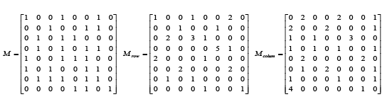
Connecting matrixes of warp and weft: As described in the previous section, after extending the rows and columns of the basic cycle matrix based on virtual weaving scale, the weaving matrix M with element (0, 1) can be constructed. If the size of weaving matrix M is m× n, which represents the digital weaving modeling using n warp yarn and m weft yarn. The number “1” represents warp nodes while the number “0” represents weft nodes. So we can derive the connecting matrix by the following method. Here, warp connecting matrix is expressed as Mrow and weft connecting matrix is expressed as Mcolum. The warp connecting matrix indicates the situation of the connection between the nodes in the column direction of the matrix. After traversing matrix M for each column, the number of continuous warp nodes (number of continuous “1” in a column of weaving matrix M) is assigned to the element which is the starting position of continuous warp nodes in the warp connecting matrix row M, and then the other continuous nodes in non-start position are assigned by “0”. It shares the same algorithm in extraction of weft connecting matrix Mcolum, but the difference is in its initialization. Because in matrix M, all weft nodes are indicated by “0”, it is not convenient for the cumulative calculation during the traversal operation. Before extraction of weft connecting matrix Mcolum, all the elements in weft connecting matrix are reversed in advance, that is: “0” represents the warp nodes and “1” represents the weft nodes. Obviously, the traversal direction is different with the method of warp connecting matrix calculation. It is to traverse on each row, and to consider the weft node connection of row direction. The following matrices show the calculation results of the above method.
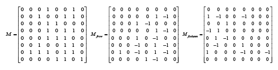
Stress matrixes of warp and weft: Stress matrix is used to describe the squeeze effect between nodes. For warp nodes, it can be considered that the stress is balanced if there are warp nodes on both their right and left sides, and the warp node in that position will not deviate in weaving. If the attribute of nodes which on the left and right sides is different, it will certainly cause deviation because of unbalanced stress. We assign “+1” or “-1” for the corresponding element in the warp stress matrix. The “+1” or “-1” represents the deviation direction of the warp node in this position. And “+1” means deviate to right, and “-1” means deviate to left. During modeling process, the actual deviation distance can be determined by the yarn diameter corresponding to the warp nodes. Similarly, the generating matrix of weft stress is according to the attribute of adjacent nodes in updown direction. “+1” means deviate upward and “-1” means deviate downward. According to the node attribute and the relationship with its adjacent nodes, the warp stress matrix Mfrow and the weft stress matrix Mfcolum can be calculated by traversing the matrix M. The following matrices show the calculation results of the above method.
Visual processing unit (VPU): In order to realize digital weaving modeling, a weaving network by selecting a set of warp and weft yarn is built firstly, and then the size of weaving modeling is determined according to customer requirements, finally the weaving nodes are drawn in all grids created in the network, so that the image of the entire weaving show the visual effects of the real yarn fabric surface. Therefore, the key point in digital weaving is how to draw and render the nodes image in the weaving network. In this paper, the bitmap unit to draw in digital weaving is defined as visual processing unit (VPU), which is composed of some related nodes. The VPU can be made up of a node or several nodes with the same attributes. After all the VPUs are generated, the digital weaving according to specified weave structure can be realized by rendering with illumination model and shape model. During the implementation of weaving modeling, we can traverse the weaving network with connecting matrix, and then it generates basic VPU image. The size and shape of VPU are determined by related yarn image information. At the same time, the yarn gathering/separating stress effect produced by float length of yarn will affect its visual effect, so adjusting the VPU shape contour by the stress matrix is also very important so that the VPU images can show the stress visual effect.
Visual modeling method of VPU
In order to generate digital weaving with sense of reality, the shape model of VPU need to be built first by analyzing the characteristics of the internal structure of the fabric. After that, the illumination model base on VPU geometry is constructed it is help to calculate the light intensity distribution on VPU surface. In the end, the highly simulated image of virtual weaving fabric can be displayed.
The shape model of VPU: Fabric is composed of warp and weft yarn in a certain organized rule (fabric organization) and its geometry structure includes warp and weft interlacing pattern, sectional area size and shape, density and buckling mode of axial line etc. As shown in Figure 5. Assuming that the fabric geometrical parameters are as follows: Sj(Sw) is the center distance of two adjacent warp yarn (weft yarn) in organization cycle; Hj(Hw) is the warp yarn (weft yarn) buckling height, which is shown by the distance between warp (weft) yarn buckling peaks and valleys along the vertical direction of the fabric surface; Dj(Dw) represents warp (weft) yarn diameter, while Djl, Djs (Dwl, Dws )represent warp(weft) yarn cross section longer and shorter diameter. Among them, the center distance between the adjacent fabric yarn Sj(Sw) and buckling height Hj(Hw) describes the interleaving morphology of warp and weft yarn, and warp (weft) yarn diameter Dj(Dw) describes the cross section morphology of fabric yarn, all can be shown as Figure 5.

Figure 5: Section model of fabric yarn.
In this paper, the cross section of the yarn in the fabric can be described by ellipse, and its cross section equation of the warp can be expressed as:
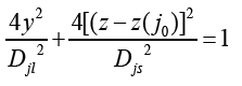 (1)
(1)
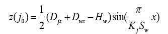
In the formula, Djl, Djs represent the longer and shorter diameter of warp yarn section; z(j0) is the coordinate of ellipse center in the direction of Z axis, which is the axis buckling shape equation in the state of the warp yarn weaving. z(j0) changes with the change of Z; similarly we can built cross section equation of weft yarn. In fact, z(j0) is the axis direction curve of the warp yarn, and for the sake of convenient, the axis direction curve of the fabric yarn is generally considered as sine or cosine curve formation, but the only difference between them is the choice of origin of coordinate. So it can be written as:
![]() (2)
(2)
In the formula (2), Zjmax is amplification coefficient. From the picture above, we know Zjmax = 0.5(Djs+Dws-Hw), while ωj is the periodic variation frequency of radial line, and it meets the following relationship:
![]() (3)
(3)
In the above formula, Tj is the periodic of sine curve, and Sw is the distance between two adjacent weft yarn centers, and Kj is the number of continuous warp yarn float. we can get:
 (4)
(4)
Substitute the above formula into formula (1), the geometric model of the surface of each warp (weft) yarn is obtained, which is the foundation to draw VPU images.
VPU illumination model: In order to get the visual image of digital weaving, a proper illumination model is needed to generate the VPU images. By the light reflection model, it is found that the light intensity reflected from the object surface to the point of view is composed of three parts: the reflected light intensity (Ie) of the ambient light, the ideal diffuse reflection light intensity (Id) and the specular light intensity (Is), and they satisfy the following relationships:
![]() (5)
(5)
In consideration of the specular reflection Is mainly describes the reflection of smooth surface, and it is not usually shown in fabric piece, we can ignore this part for its little effect on visual sense. So the reflection light of yarn surface can be written as I = Ie + Id, while the reflected ambient light intensity Ie is a constant in the simple reflection model and the scattered reflection light intensity Id can be indicated as:
![]() (6)
(6)
Where Ip and Kd are constants, so the reflection light intensity changes only with the cosine of the incident angle. As the surface of fabric is made up of warps and wefts that are perpendicular to each other and in the space above the fabric, we can only see the surface image of all the nodes, so how to draw VPU image is the key problem.
In this paper, it takes two steps to draw VPU image. Firstly, viewed from the axis section, warps and wefts show a sine curve on the surface of fabric. The edge curve of the cross section of the warp or weft yarn axis changes meets sine curve on the surface of the fabric. Taking the warps as an example, we can define a VPU as a processing unit shown in Figure 6. This curve represents the changing curve of axis zj(x)k of the kth VPU.

Figure 6: State chart diagram of warp VPU.
It is assumed that the light source and the viewpoint are in the infinite distance above the fabric, so the incidence angle of point O at the center of VPU surface axis is 0º. Based on relationship (6), the point of the strongest reflection light intensity is O. With the change of position along the curve, the light intensity will get weaker and weaker. For arbitrary point on the curve P, the distance PO’ between the point P and the center line is Δx and incidence angle is β, thus:
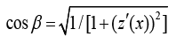 (7)
(7)
In the formula z(x) = Asin(ωx), we can get z(x)’ = Aωcos(ωx) and x = (T/4) ± Δx, so β can be got by the following formula:
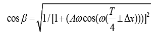 (8)
(8)
Parameters A, ω and T in formula (8) can be determined by formula (3). According to formula (8), we can get the light intensity of P:
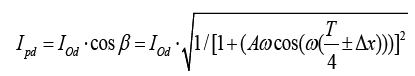 (9)
(9)
Now we analyze the surface of VPU according to yarn section. In this paper, we assume that the cross section of yarn is circular, and its diameter can be easily obtained by imaging system. Supposing that there is an arbitrary point R on the circular curve which is corresponding to the incident angle , and the perpendicular distance between R and center point line is y, we can work out:
![]() (10)
(10)
So the scattered reflection intensity of R can be expressed as:
![]()
Wefts VPUs can be processed with a similar way.
Implementation of digital weaving modeling
We first construct a weaving network based on the weaving size and the number of warps and wefts, and then we can determine the node attribute using the weaving matrix extended by the basic cycle matrix. Merging the nodes with connecting matrix and adjusting them by stress matrix under the constraint of yarn external dimensions, we can get all VPUs involved in digital weaving modeling. The distribution characteristics between the adjacent nodes with the same attribute and stress visual features among yarns can be shown. All VPUs are drawn according to the corresponding shape and illumination model in weaving network and the digital weaving based on real yarn can be realized.
Experiment
According to the method mentioned above, we have developed a set of digital weaving modeling software. The Figure 7 has shown the software interface. In the software, the main functions include image collecting control, image preprocessing, weaving modeling and so on. Especially through VPU modeling function, we can realize digital weaving modeling based on the information of physical yarns and fabric pattern.

Figure 7: The software interface of digital weaving modeling.
The experimental steps of digital weaving modeling can be described as follows:
(1) Information extraction of physical yarn: All yarns involved in digital weaving modeling are installed in the imaging system for detection after being given a number. Computer is calculated the actual physical size according to the calibration coefficient and the size of the image captured. At the same time, the color of the yarn is extracted and then the yarn index information table is built.
(2) Generating the weaving network. A preliminary weaving network with certain size and grids number is built on the basis of the predetermined weaving size and the number of warps and wefts, in which each section of the warp or weft can be seen as interlacing point in the network and is filled with a warp or weft node. Figure 8 the weaving network of different sizes.

Figure 8: The weaving network of same weaving sizes with different number of yarns (a) 8*8, (b) 15*15, (c) 100*100.
(3) The attributes of nodes are determined by the basic cycle matrix. Firstly, the weaving matrix can be obtained by extending the selected basic cycle matrix along the warp and weft direction respectively, and then the attribute of all nodes in the network can be determined. Then the attributes of all nodes can be determined according to the corresponding relationship between the weaving matrix and the weaving network.
(4) Generation of connecting matrix and stress matrix. Traversing the weaving matrix, the connecting matrix Mrow, Mcolum and stress matrix Mfrow, Mfcolumn can be obtained according to the method mentioned above.
(5) Generation of visual processing unit (VPU). It takes three steps to generate VPU. Firstly, the network node is traversed and continuous warp or weft nodes with the same attributes will be merged according to the warp and weft combined matrix Mrow and Mcolum. Then the size and shape of VPU are determined by the corresponding physical yarn image and the contour of the VPU is adjusted by the stress matrix. Finally, the shape model is used to deal with all nodes to ensure the visual effect.
(6) Illumination effect and color processing of visual processing units. All VPUs image are drawn according to the illumination model and their color which come from the color index table.
(7) The processing of whole weaving effect and final display of the overall simulation results.
Figure 9 shows the weaving image composed of VPU after the processed by model illumination and Figure 10 shows the weaving image processed by the color model.

Figure 9: The weaving image drawn with VPUs.

Figure 10: The weaving image processed by illumination model and color.
Figure 11 shows the simulation results of digital virtual weaving

Figure 11: The simulation results of digital virtual weaving.
Conclusions
Fabric appearance simulation is the key technology in the digital textile and it is having significant application value. In this paper, we proposed a realization method of digital weaving modeling based on information of physical yarns and weave pattern of fabric. A preliminary weaving network with certain size and nodes number would be constructed based on the preset weaving scale and number of warps and wefts. Basic cycle matrix is used to extend the rows and columns, so as to get the corresponding weaving matrix and determine the node attribute. Connecting matrix is used to merge the nodes, the size and shape of all nodes can be determined based on the corresponding relationship between yarn physical dimensions and the image size. A VPU will be got after the adjustment by stress matrix. In the end, we deduced the vision model on the basis of its shape model which can realize rendering on all VPUs. The method proposed in the article can significantly reduce the calculating costs of fabric appearance simulation algorithm.
Funding
This project is supported by the National Natural Science Foundation of China (Grant No.51575099), The Shanghai Natural Science Foundation (Grant No. 15ZR1401700) and the Pujiang Program (No. 14PJ1400100).
References
- Mine A, Behcet B, Halil RA (2012) The effect of fabric constructional parameters on percentage reflectance and surface roughness of polyester fabrics. Text Res J 82:700–707.
- Piti I, Steve M (2012) Specular Reflection from Woven Cloth. ACM Transactions on Graphics 31.
- Jiahua Z, George B, Dejun Z, Chen L, Guiqing L, et al. (2013) IDSS: A novel representation for woven fabrics. IEEE Transactions on Visualization and Computer Graphics. 19:420-431.
- Zhou D, Zhou L, Sun J (2013)A novel feedback error-correcting algorithm for automatic recognition of the color and weave pattern of yarn-dyed fabrics. Text Res J83:673-689.
- Toshihiro S, Jun-YT, Shinji O, Akira K (2008) Automatic Weave Diagram Construction from Yarn Positional Data of Woven Fabric. Text Res J. 78:745-751.
- Naik NK, Ganesh VK (1996)An analytical method for plain weave fabric composites. Butterworth Heinemann 26:281-289.
- Kuo CC, Liu SC, Yu WH (2000)Woven fabric analysis by image processing. Part I: identification of weave patterns. Text Res J 70: 481–485.
- Kang TJ, Kim CH, Oh KW (1996)Automatic recognition of fabric weave patterns by digital image analysis. Text Res J 69: 77–83.
- Mingxing X, Zhaofeng G (2010)A Model of Rigid Bodies for Plain-Weave Fabrics Based on the Dynamics of Multibody Systems. Text Res J 80:1995-2006.
- Xin W, Nicolas DG, Emil MP (2011) Fabric Texture Analysis Using Computer Vision Techniques. Ieee Transactions On Instrumentation And Measurement 60:44-56.
- HyunAK,SeungJK(2010) Simulation of the weave structural design of synthetic woven fabrics. Fibers and Polymers 11:905-910.
- Tae JK, Chang HK, Kyung WO (1999) Automatic Recognition of Fabric Weave Patterns by Digital Image Analysis. Text Res J 69:77-83.
- Grundler D, Rolich T (2013) Matching Weave and Color with the Help of Evolution Algorithms. Text Res J 73:1033-1040.
- Iman S,Oleg B, Joachim D, Henrik WJ (2013) A Practical Microcylinder Appearance Model for Cloth Rendering. ACM Transactions on Graphics J 32: 1-12.
- Dmitry SI, Stepan VL, Alexander EB, Mehmet K, Ignaas V (2009)A comparative study of tensile properties of non-crimp 3D orthogonal weave and multi-layer plain weave E-glass composites. Elsevier J 40:1144-1157.
- Kanthikannan S, John W, Clinton C (1997) Modal technique for three-dimensional global/local stress analysis of plain weave composites. Elsevier J 39:145-156.
- Wilfried R,Yordan K (2011)Geometry modelling of warp knitted fabrics with 3D form. Textile Research Journal J 81:437-443.
- Xiaogang C, Lindsay WT, Li JT (2011)An overview on fabrication of three-dimensional woven textile preforms for composites. Text Res J 81:932-944.
- Tianyong Z, Yu C, Shujuan J, Xiangjun Z (2011) Study on non-devastating measurement and reconstruction of the three-dimensional geometric structure of woven fabrics. Text Res J 81: 1027-1038.
- Ping Z, Tao Y, Yunlong S, Xinxing T (2013) Research on computer-aided analysis and reverse reconstruction for the weave pattern of fabric. Text Res J83:298–310.