Spanish
  Chinese
  Russian
  German
  French
  Japanese
  Portuguese
  Hindi
Hindi Review Article, J Nucl Ene Sci Power Generat Technol Vol: 11 Issue: 3
Experimental Analysis of PEM Fuel Cell with Vulcan Carbon/Graphene Porous Inserts for Efficient Water Management-Zig- Zag and Inline Pattern
Prasanna Mishra*, Mathan Chandran, Thanarajan Kumerasan,Dineshkumar Ponnaiyan, V. Kirithik, M. Aswath, V. Pranav,Karthikeyan Palaniswamy
Department of Automobile Engineering, PSG College of Technology, Coimbatore,Tamil Nadu, India
*Corresponding Author: Prasanna Mishra, Department of Automobile Engineering, PSG College of Technology, Coimbatore, Tamil Nadu, India, Tel: 9490303888; E-mail: prasannamishra234@gmail.com
Received date: 25 February, 2022, Manuscript No. JNPGT-22-45684;
Editor assigned date: 01 March, 2022, PreQC No. JNPGT-22-45684(PQ);
Reviewed date: 14 March, 2022, QC No. JNPGT-22-45684;
Revised date: 21 March, 2022, Manuscript No. JNPGT-22-45684(R);
Published date: 24 March, 2022, DOI: 10.4172/2325-9809.1000260
Citation: Mishra P, Nivedetha B (2021) Enhancing Security in Wireless Sensor Networks. J Nucl Ene Sci Power Generat Technol 11:3.
Abstract
A fuel cell is an electrochemical device which converts chemical energy into electrical energy without any intermediate steps. The estimated reserve of oil and gas is will last up to 2042, its advisable to shift to alternative energy sources for energy generation application. Considering the efficiency, economy and environment, hydrogen fuel cells are potential source of energy for both automotive and stationary power generation. From this its clear that the fuel cells have highest energy density compared to other sources, they can be used for numerous applications.
Keywords: Fuel cell, Electrochemical device, Electrical energy, Efficiency
Introduction
Hydrogen of high purity is passed through anode and oxygen is passed through cathode. The Proton exchange membrane allows only protons to pass through blocking the gases. The electrons produced by the hydrogen oxidation reaction flows through the external circuit from anode to cathode. The electro chemical reactions are as follows.
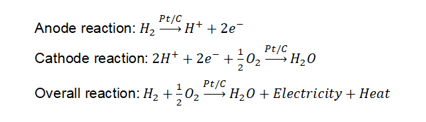
From the electrochemical reactions, it is clear that water and heat are produced as by-product, which are to be removed for the fuel cell to function effectively. This work concentrates on passive removal of water formed in between the rib and the Gas Diffusion Layer (GDL) for effective mass transportation by employing porous inserts positioned in the modified serpentine flow channel. Porous inserts were made of two different materials, namely Vulcan carbon and Graphene powder. These materials were selected as they are highly conductive, which in turn will not add up the cell’s internal resistance.

Figure 1: Simplified ragone chart.
Literature Review
Flow channel design-modification of serpentine flow channelThis work evaluates and compares the performance of serpentine flow channel with the modified serpentine flow channel developed to enhance the water removal from the rib and GDL interface. 25 cm2 active area is selected for this work with Land to Channel dimensions 2 × 2 mm. Serpentine flow channel and modified serpentine flow channel namely and zig-zag pattern serpentine flow channel are shown in the below Figure 2.

Figure 2: Serpentine flow channel; inline serpentine flow channel; zig-zag serpentine flow channel.
Porous inserts material selection and sizing: The porous inserts should have qualities like good stability, thermal and electrical conductivity, high porosity to absorb the water formed, high gas permeability. These material properties have great influence on absorption of accumulate water. In this work the channels used have L:C ratio as 2:2 which means that width and height of the porous inserts are 2 mm × 2 mm. To study the peak power performance of the PEMFC porous inserts of length 2 mm and 4 mm has been selected. To avoid the back flow of the reactant the porous inserts are filled along the landing of cathode flow channel.

Figure 3: Porous insert dimensions.
Process Flow
- Machining of flow fields with different flow field design like serpentine, serpentine with inline and zig-zag pattern of active area 25 cm2.
- Fabrication of porous inserts of required size L × B × H: 2 mm × 2 mm × 2 mm and 4 mm × 2 mm × 2 mm of 80 to 90% porosity. Vulcan Carbon and Graphene will be used as porous inserts.
- Experimental studies on 25 cm2 PEMFC with serpentine flow field, serpentine with 4 mm porous inserts arranged in uniform and zig-zag pattern is conducted.
- Comparing the performance of 25 cm2 active area with and without porous inserts on cathode flow field to analyse the water removal capability.

Figure 4: Process flow diagram.
First step is to mix 20 mg of Polyvinyl Alcohol (PVA) in 20 ml of distilled water. Stir the solution using magnetic stirrer for 5 hours, maintaining a constant temperature of 90oC at 1000 rpm. Once the PVA is ready, The Vulcan Carbon/Graphene is taken in the mortar and droplets of PVA solution is added using an ink-filler and grinded using a pestle till the Vulcan Carbon/Graphene and PVA solution mixed together to form a slurry. Once the mixture attains clay state, it is shaped to meet the required dimensions and dried in a furnace at 100°C for 15 minutes in order to vaporize the PVA. The dried porous inserts are placed in the space provided on the Graphite plate. Porous inserts are prepared for these two sizes:
- 2 mm × 2 mm × 2 mm.
- 4 mm × 2 mm × 2 mm.
The porosity of the inserts also plays a vital role in enhancing the performance of the PEMFC. For this work porous inserts with porosity 80-90% is selected. The porosity of the inserts is calculated using Liquid Absorption method. The dry weight of the insert is taken before dipping it in glycerol. The inserts are dipped into Glycerol for 15 minutes and wet weight is taken. Porosity can be calculated.

Figure 5: Preparation of porous inserts.
In order to hydrate the Membrane Electrode Assembly (MEA) which has dried during hot pressing, conditioning or the MEA should be activated. Based on the experimental trails, the conditioning of MEA involves the following steps.
- Initially a constant voltage of 0.7 V is held for 3600 seconds using voltage pulse method.
- After first step, a cyclic looping process in which voltage of 0.7 V is held for 900 seconds and following it by a voltage of 0.4 V is maintained for same duration of 900 seconds. This loop is repeated 3 times.
By this repeated higher and lower voltage value the current value reaches a peak value in that particular voltage range. This method ensures that the MEA is performing at its peak power value and that a majority of the catalyst sites are activated.

Figure 6: MEA assembly active are 25 cm2 (L × B: 5 cm × 5 cm).
The graphite plate, PEM, Current collector, Insulator, End plates are assembled together to form a single cell. Now the Anode is connected to the Hydrogen gas and Cathode is connected to the Oxygen gas. Temperature sensor is also connected to the cell to measure the cell temperature. All these connections are connected to the test rig which is in turn connected to the computer, which is installed FC Lab module. The power supply is switched on and the input gases are also opened. Once the gases reach the membrane that is coated with Platinum over carbon, which is going to act as catalyst, the reaction starts current flow through the circuit and the readings are displayed in the FC Lab module screen. Types of flow channels used in this study is tabulated in Table 1.

Figure 7: Bio-logic FCT fuel cell test station used for performance evaluation.
| S.No | Anode | Cathode | Insert material | |
|---|---|---|---|---|
| Vulcan carbon | Graphene | |||
| 1 | Serpentine | Serpentine | - | - |
| 2 | Serpentine | Serpentine with 2 mm porous inserts -Inline pattern | ✓ | - |
| 3 | Serpentine | Serpentine with 2 mm porous inserts - Zig-zag pattern | ✓ | - |
| 4 | Serpentine | Serpentine with 4 mm porous inserts - Inline pattern | ✓ | ✓ |
| 5 | Serpentine | Serpentine with 4 mm porous inserts -Zig-zag pattern | ✓ | ✓ |
Table 1: Types of Flow channels used with porous insert materials.
Results and Discussion
Performance characteristics of 25 cm2 fuel cell with serpentine flow channelFrom Figure 8 for serpentine-serpentine flow channel with L:C ratio as 2:2, the maximum power density is 0.239 W/cm2 and peak current density is 0.570 A/cm2. These values are kept as benchmark and further experiments are proceeded. Figure 9 shows the performance curve of 36 cm2 PEMFC with 2 mm porous inserts arranged in uniform pattern. The peak power density is 0.295 W/cm2 and corresponding current density is 0.732 A/cm2. The increase in power density is 23.43% and current density is 28.42% compared with 25 cm2 serpentine flow field. Figure 10 shows the performance curve of 25 cm2 PEMFC with 2 mm porous inserts arranged in zig-zag pattern. The peak power density is 0.338 W/cm2 and peak current density is 0.871 A/cm2. The increase in power density is 16.55% and current density is 19.31% compared with 25 cm2 inline pattern flow channel. Figure 11 shows the performance curve of 25 cm2 PEMFC with 4 mm porous inserts arranged in inline pattern. The peak power density is 0.332 W/cm2 and peak current density is 0.778 A/cm2. The decrease in power density is 1.77% and decrease in current density is 11.49% when compared with 2 mm zig-zag pattern. The decrease in performance is due to the positioning of the inserts, that they are in straight line failing to collect maximum water accumulated in the rib and GDL interface.

Figure 8: 25 cm2 Serpentine flow channel polarization curve.

Figure 9: 25 cm2 Serpentine with 2 mm Vulcan carbon porous inserts-inline pattern polarization curve.

Figure 10: 25 cm2 Serpentine with 2 mm Vulcan carbon porous inserts zig-zag pattern polarization curve.

Figure 11: 25 cm2 Serpentine with 4 mm Vulcan carbon porous inserts-inline pattern polarization curve.
Figure 12 shows the performance curve of 25 cm2 PEMFC with 4 mm porous inserts arranged in zig-zag pattern. The peak power density is 0.348 W/cm2 and peak current density is 0.839 A/cm2. The increase in power density is 2.96% and current density decreased around 3.45% when compared with 4 mm inline pattern. Figure 13 shows the performance curve of 25 cm2 PEMFC with 4 mm graphene porous inserts arranged in inline pattern. The peak power density is 0.348 W/cm2 and peak current density is 0.893 A/cm2. There is no increase in power density but current density increased around 6.44% when compared with 4 mm Vulcan carbon porous inserts arranged in zig-zag pattern. Figure 14 shows the performance curve of 25 cm2 PEMFC with 4 mm graphene porous inserts arranged in inline pattern. The peak power density is 0.386 W/cm2 and peak current density is 0.991 A/cm2 The increase in power density is 10.92% and current density is 10.97% compared with 25 cm2 4 mm graphene porous inserts-inline pattern flow channel.

Figure 12: 25 cm2 Serpentine with 4 mm Vulcan carbon porous inserts – zig-zag pattern polarization curve.

Figure 13: 25 cm2 25 cm2 Serpentine with 4 mm Graphene porous inserts-inline pattern polarization curve.

Figure 14: 25 cm2 Serpentine with 4 mm Graphene porous inserts zig-zag pattern polarization curve.
Conclusion
There is a considerable amount of power increase when we shift from 2 mm porous inserts to 4 mm porous inserts. In addition, it can also be observed that changing the porous inserts material from Vulcan carbon to graphene also has a positive effect on the fuel cell performance. This is due the higher conductivity of graphene compared to Vulcan carbon. Among inline and zig-zag pattern, later showed higher performance as the zig-zag positioning of inserts collected the water from the rib-GDL interface more uniformly throughout the cell. In future, the dimension of the porous inserts will be increased and the performance will be evaluated. Further porous ribs will also be considered for evaluation, which needs high level design and machining capability.
References
- Shafiee S, Topal E (2009) When will fossil fuel reserves be diminished? Energy Poli 37: 181-189.
- Stambouli AB, Traversa E (2002) Fuel cells, an alternative to standard sources of energy. Renew Sustain Ener Rev 6: 295-304.
- de-Troya JJ, Alvarez C, Fernandez-Garrido C, Carral L (2016) Analysing the possibilities of using fuel cells in ships. Int J Hydro Ener 41: 2853-2866.
- Ma T, Zhang Z, Lin W, Cong M, Yang Y (2021) Impedance prediction model based on convolutional neural networks methodology for proton exchange membrane fuel cell. Int J Hydro Ener 46: 18534-18545.
- Karthikeyan P, Vasanth RJ, Muthukumar M (2015) Experimental investigation on uniform and zigzag positioned porous inserts on the rib surface of cathode flow channel for performance enhancement in PEMFC. Int J Hydro Ener 40: 4641-4648.
- Karthikeyan M, Karthikeyan P, Muthukumar M, Kannan VM, Thanarajan K, et al. (2020) Adoption of novel porous inserts in the flow channel of pem fuel cell for the mitigation of cathodic flooding. Int J Hydro Ener 45: 7863-7872.
- Zhao J, Tu Z, Chan SH (2021) Carbon corrosion mechanism and mitigation strategies in a proton exchange membrane fuel cell (PEMFC): A review. J Power Sourc 488: 229434.
- Iqbal MZ, Rehman AU, Siddique S (2019) Prospects and challenges of graphene based fuel cells. J Ener Chem 39: 217-234.