Research Article, J Nucl Ene Sci Power Generat Technol Vol: 11 Issue: 6
Experimental and Theoretical Study for the Effects of Different Reflector Types on the Neutronic Parameters of the MNSR Reactor
Bassem Assfour1*, Saadou Dawahra2, Walaa Helal2
1Department of Chemistry, Atomic Energy Commission, Damascus, Syria
2Department of Nuclear Engineering, Atomic Energy Commission, Damascus, Syria
*Corresponding Author: Bassem Assfour, Department of Chemistry, Atomic Energy Commission, Damascus, Syria Tel: 963 112132580 E-mail: cscientific15@aec.org.sy
Received: 13 January, 2021, Manuscript No. JNPGT-21-24529; Editor assigned: 20 January, 2021, PreQC No. JNPGT-21-24529 (PQ); Reviewed: 02 Febraury, 2021, QC No. JNPGT-21-24529; Revised: 28 June, 2022, QI No. Q-24529; Manuscript No. JNPGT-21-24529; Published: 26 July, 2022, DOI: 10.4172/2325-9809.1000293
Citation: Assfour B, Dawahra S, Helal W (2021) Experimental and Theoretical Study for the Effects of Different Reflector Types on the Neutronic Parameters of the MNSR Reactor. J Nucl Ene Sci Power Generat Technol 11:6.
Abstract
Nowadays, most research reactors utilizing highly enriched uranium fuel are planned to be converted to use low enriched uranium fuel. As a result of the conversion, the neutron thermal flux (?th) decreased by 10%. Such lose in the neutron flux can be compensated by introducing a suitable reflector material around the reactor core. Three different type of reflectors have been investigated, graphite, heavy water and light water. The effect of each type on the reactivity and ?th distribution was investigate by monitoring the reactor parameters after inserting containers filled with a reflector material inside inner irradiation site. Furthermore, a theoretical analyses study has been conducted using the MCNP4C code. The analyses revealed that theoretical and experimental values are comparable. Our results indicate that graphite is the most preferred mateial among the studied reflector groups. The ?th in the Inner Irradiation Tube (IIT) was increased by 12, 11, and 2% for graphite, light water and heavy water, respectively. Moreover, heavy water introduced the highest reactor reactivity, 0.6 mk, followed by light water and graphite with the values: 0.323, and 0.127 mk, respectively. Finally, the graphite reflector can be a suitable reflector, since it compensates the decreasing in the ?th with minimum effect on the core reactivity.
Keywords: MNSR; Reflectors; MCNP; Neutron flux; Graphite; Heavy water
Introduction
MNSR stands for “miniature neutron source reactor”. It is a research reactor uses light water as a moderator, pure beryllium as a reflector and highly enriched uranium as a fuel [1]. The reactor is mainly used for Neutron Activation Analysis (NAA). Ten vertical holes are designed for sample irradiation, five of them are located in the annulus beryllium reflector and called Internal Irradiation Sites (IISs) and the rest are the external irradiation sites (Figure 1). At the same power level, the neutron flux at an IIS for a generic the U-235 enriched 19.75% core is approximately 10% lower than that for the U-235 90% enriched core. The power therefore for the U-235 19.75% enriched core should be around 10% higher in order to retain a neutron flux of 1.0 × 1012 cm-2.s-1 at the IIS [2,3]. Many studies have been made for the MNSR conversion from the U-235 enriched 90% to U-235 19.75% enriched fuel [4,5]. This conversion process demands an increase in U-235 loading to achieve sufficient excess reactivity in order to overcome parasitic absorption in U-238 and to match the cycle length with U-235 90% enriched fuel. As a result of higher fuel loading, the neutron spectrum will become harder as well as Фth will decreased. The maximum relative decrease in the Фth of U-235 90% enriched and U-235 19.75% enriched fuels in the IIS was 10%.
These losses can be compensated by introducing a suitable reflector material. Such material will improve the average neutron flux thus increasing the excess reactivity in the core. In research reactors, different types of material are used as neutron reflectors in the reactor core. The reflector yield increases with the decrease in the absorption cross-section and increase in the scattering cross-section of the reflector [6,7]. The use of reflectors in the reactor core provides some advantages such as reduction in the critical size of the reactor core as well as reduction in the critical mass of the fuel. To assess the effect of different reflector materials on the neutronic parameters of the MNSR research reactor such as the reactivity and Фth in inner irradiation sites, a chain of TPCC filled of reflector material was used. The reactivity effects of flooded inner irradiation sites in the MNSR reactor were evaluated both numerically and experimentally [8]. It was found that the reactivity increase for each cm of the water is 4.5e-3 mk/cm. In this work, three reflector materials such as: Heavy water, graphite and light water were used to study the efficiency of the reflector on the MNSR parameters. The reactor reactivity and the neutron flux in inner radiation sites were calculated and compared for each reflector material. Several materials are traditionally used as neutron reflectors in the reactor. Such as water, graphite and hevy water [9-11].
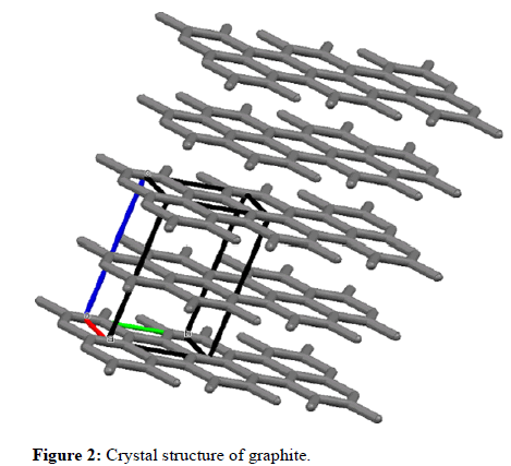
Water is a universal material that could be used as a moderator, a coolant and a reflector at the same time. The scattering cross-section of hydrogen, and its ability to slow neutrons rapidly down to thermal energy makes water an obvious choice as a reflector. However, water has relatively low density and suffers from lack of structural functions. Graphite is widely used as a moderator or reflector in nuclear reactors due to its desirable nuclear, physical and chemical properties. Its properties include low cost, non-oxidation, simple manufacturing technology and high temperature stability. It is made up of layers of carbon atoms bound together in the form of repetitive hexagonal patterns. The separation between two consecutive layers is about 3.35 Å as shown in Figure 2.
Dsiadvantages of graphite include: The return of fast neutrons from the graphite reflector to the reactor is relatively small, and chemical interaction of graphite with reactor coolant, could lead to a chemical reactions. Heavy water contains deuterium (an isotope of hydrogen) instead of hydrogen, it is also knows as deuterium oxide (DO2). It is known to be used in low enriched reactor (CANDU) due to its ability to control the energy of prompt neutrons. Moreover, high-energy gamma rays resulting from some fission products such as (140Ba-140La) in irradiated fuel may induce the generation of light neutrons from heavy water according to the reaction D (γ, n) H, which increases the intensity of nitrous flux. This phenomenon is highly important in case of the reactor shut down.
Materials and Methods
Material characterization
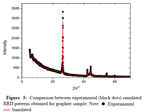
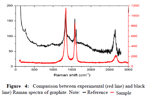
The graphite sample was characterized by two different techniques, X-Ray diffraction and Raman spectroscopy. The XRD diffraction pattern was recorded on STADI-P STOE, with Cu K_α radiation (λ=1.54060 Å) and a germanium monochromatic operated at 50 kV and 30 mA in the range 5° to 70°. Figure 3 represents the collected XRD diffraction pattern (black dots) of the sample together with the simulated pattern of graphite (red line). A good agreement between and the experimental and simulated diffraction spectrums is clear. Raman analysis was carried at room temperature on a Thermo Scientific Nicolet 6700 Fourier transform Raman Spectrometer, Madison, USA. It is equipped with Nd: YAG laser operating with an exciting frequency at 1064 nm. Indium gallium-arsenide detector operating at room temperature is used for signal detection. Spectra were measured at 8 cm-1 resolution in the region from 100 to 4000 cm-1 and a total of 200 scans. A separate background spectrum was subtracted after pattern collection.
Raman pattern of the graphite sample is displayed in Figure 4. It is clear that Raman shifts are fully consistent with the main frequencies over the entire spectrum field, indicating that the structure of the material used corresponds to the expected structure of graphite. The term 'heavy water' refers to a highly enriched water mixture that contains mainly deuterium oxide D2O. For instance, the enrichement of heavy water used in CANDU reactors is 99.75%. Therefore, it is essiential to determine the enrichement of our sample. The heavy water content of the sample is determined by Deuterium dilution method using IRMS IZO prim mass sepctrometery from GV instrument. The results revealed that the ratio D2O/H2O is about 99.06%, which is close (and within the limits of error) to the percentage stated in the sample certificate of 99%.
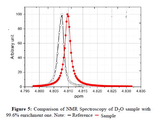
For further investigation, we compared the proton NMR spectra of our samples with the spectra of a reference sample, where the concentrations of D2O in reference is 99.6%. The width of the water resonance in a NMR spectrum depends on the amount of light water present. The larger concentration of H2O the greater the width of the water line. This phenomenon is known as radiation damping. Figure 5 presents the 400 MHz proton NMR spectra of the two samples. It is clear that the width of the water resonance in a NMR spectrum of our sample is closer to that in the reference sample, indicating that the concentrations of H2O in both samples are comparable.
Experimental procedure
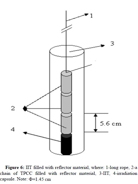
In this study, three different sets of experiments were conducte. In each experiment, as illustrated in Figure 6, chains of Interconnected Polyethylene Containers (TPCC) filled with the same reflector material, are inserted into the IIT form the top of the reactor using a long rop. Therefore, the void inside the IIT will be filled with considered reflector material. Consequently, a gain in excess reactivity and in the Фth will be obtained. The procedure adopted for the experimental approach was the following: All measurements were made on low power level. The initial reactor parameters were: Фth was 2 × 10⁹ n.cm-2.s-1, the control rode position was 137 mm, and the IITs were empty. After adding the chains filled with reflector material into the IITs, the control rode position will be withdrawal into the reactor to compensate the reactivity gain caused by the reflector material. Stable critical position of the control rode before and after the loading of the chains gave the total reactivity worth of these chains. The experimental relationship of the control rod reactivity (ρ) at different withdrawal positions (z) was evaluated as following:
ρ(z)=1.08 × 10⁻⁵+4.626 × 10⁻⁴. z+2.644 × 10-4.z2+3.238 × 10-7.z3–8.11 × 10-9.z4+1.687 × 10-11.z5
where: ρ-reactivity (mk), and z-height (mm).
The reactivity gain of each reflector material can be calculated using equation at two positions (reactivity with reflector material-reactivity without reflector material).
Analytical study
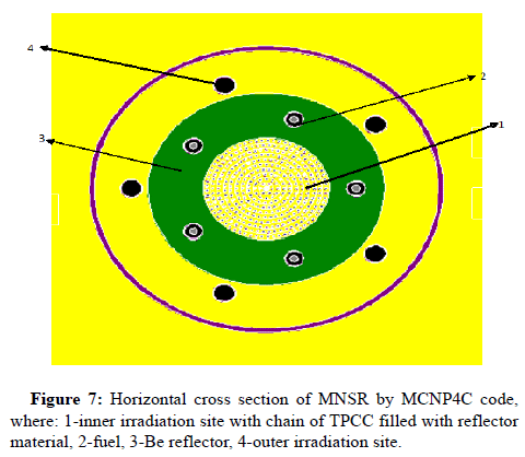
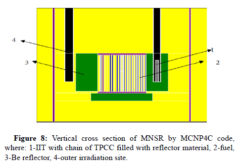
In this work, MCNP (Monte Carlo N-Particle) version.4.0 simulation package has been used for reactor calculations [12]. MCNP is a general purpose transport code, which uses Monte Carlo method for modeling the interaction of different type of particles with materials. The Monte Carlo method has been practically useful for calculating the MNSR reactor parameters. A three dimensional model for MNSR reactor was prepared for evaluating the effect of reflector material type on both reactivity and neutron flux. In this model, the reactor geometry and the fuel configuration inside the core were kept unchanged as in safety analysis report. Whereas, the void inside the IISs was changed to account for the chains of polyethylene containers inserted in the IITs (Figure 7 and 8). KCODE card is used to determine the keff (reactivity) parameter. A total of 400 cycles of iterations on a nominal source size were performed, in each cycle, 15000 particles were used in order to lower the estimation of the statistical error. Initially, the first 50 cycles were ignored to ensure the homogeneity distribution of the neutron source. The Фth distributions in the IIT was calculated using the F5 tally.
Results and Discussion
The aim of this work is finding reflector material, which gives the maximum Фth and minimum effect on the reactor reactivity. Table 1 shows the experimental reactivity values for three reflector types. These values were calculated using experimental equation. The worth of reflector materials were 0.6, 0.323 and 0.127 mk for heavy water, light water and graphite respectively [13]. These values for one cm3 of reflector material also calculated and found to be: 9.393E-3, 5.056E-3 and 2.946E-3 mk/cm3. The heavy water was gave the maximum reactivity, followed by light water and graphite. Table 2 shows the analytical reactivity values for three reflector types. These values were calculated using MCNP4C code. The worth of reflector materials were 0.59, 0.339 and 0.125 mk for Heavy water, light water and graphite respectively. These values agree well to the experimental values as can be seen in this table.
| Reflector | Control rod position (mm) | Reactivity | |||
|---|---|---|---|---|---|
| Before adding capsules | After adding capsules | (mk) | (mk/g) | mk/cm3 | |
| D2O | 137 | 110 | 0.6 | 8.66E-03 | 9.39E-03 |
| H2O | 137 | 117 | 0.323 | 5.06E-03 | 5.06E-03 |
| C | 137 | 122 | 0.127 | 1.34E-03 | 2.95E-03 |
Table 1: Reactivity vs control rod position for three reflector chains (each chine consists of three capsules).
| Reflector | Reactivity | |||||
|---|---|---|---|---|---|---|
| MCNP | Experimented | |||||
| (mk) | (mk/g) | mk/cm3 | (mk) | (mk/g) | mk/cm3 | |
| D2O | 0.59 | 8.40E-03 | 9.24E-03 | 0.6 | 8.66E-03 | 9.39E-03 |
| H2O | 0.339 | 5.31E-03 | 5.31E-03 | 0.323 | 5.06E-03 | 5.06E-03 |
| C | 0.125 | 1.32E-03 | 2.90E-03 | 0.127 | 1.34E-03 | 2.95E-03 |
Table 2: Comparison between MCNP and experimental results for three reflector materials.
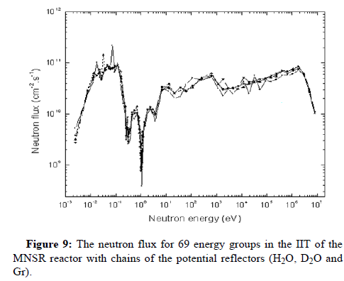
Table 3 shows the MCNP results of the maximum Фth (in IIT). The maximum Фth were: 1.05E+12, 1.15E+12 and 1.16E+12 n.cm-2.s-1for the heavy water, light water, and graphite respectively. As it can be seen from this table, the graphite reflector gave the highest Фth followed by light water and heavy water reflectors. A comparison of these values with referenced values which were calculated by 2,3,13 can be seen in this Table as well. The calculated results have good agreements with the results calculated for U-235 90% enriched fuel without capsules. The results showed that the graphite reflector can be used since it compensated the decreasing in the Фth (from 1.03E12 n.cm-2.s-1 for U-235 90% enriched, 90% UAl to 9.34 E11 n.cm-2.s-1 for U-235 19.75% enriched, 12.6% UO2). Figure 9 shows the Фth for 69 energy groups in the IIT of the MNSR reactor for the existing U-235 90% enriched fuel with beryllium reflector and the chains filled with potential reflectors (H2O, D2O and Gr). The max relative difference in the Фth in the IIT is less than 10%, depending on the reflector type.
| Reflector type | Thermal flux (n/cm2.s) (0-0.625 eV) | |||
|---|---|---|---|---|
| This work with capsules ( U-235 90% enriched ) |
This work without capsules (U-235 90% enriched) | Without capsules (U-235 90% enriched) | Without capsules (12.6% UO2) | |
| - | 1.04E+12 | 1.03E+12 | 9.34 E+11 | |
| D2O | 1.05E+12 | - | - | - |
| H2O | 1.15E+12 | - | - | - |
| C | 1.16E+12 | - | - | - |
Table 3: Фth for different reflectors in the IIT.
Conclusion
Experiment and analytical studies were successfully accomplished in order to evaluate the effects of the deferent reflector materials namely, D2O, H2O and Gr on the neutronic parameters of the MNSR core. Good agreements were noticed between the results of 3-D MCNP model (in this work and previously published results) and the experimental results for the MNSR reactor. The Graphite reflector has the most efficient in this reflector group since it gave the highest gain in Фth which was equal to 1.16E+12 n.cm-2.s-1. It followed by light water and heavy water respectively. The heavy water reflector gave the highest reactivity worth which was equal to 0.127 mk. It followed by the light water and graphite respectively. Finally, the results showed that, the graphite-beryllium reflector (Beryllium as annular reflector+chins of graphite in IIT) was the best material, since it compensated the flux losein IIS-due to the conversion of the MNSR U-235 90% enriched fuel to the U-235 19.75% enriched fuel- with minimum effect on the MNSR reactivity worth.
Acknowledgement
The authors thank Professor I. Othman, Director General of the Syrian Atomic Energy Commission, for his encouragement and support.
References
- CIAE (1993) Safety analysis report (SAR) for the Syrian miniature neutron source reactor, China.
- Dawahra S, Khattab K, Saba G (2015) A comparative study of the neutron flux spectra in the MNSR irradiation sites for the HEU and LEU cores using the MCNP4C code. Appl Radiat Isotopes 104: 67-73.
- IAEA-TECDOC-1844 (2018) Analyses supporting conversion of research reactors from high enriched uranium fuel to low enriched uranium fuel. The Case of the Miniature Neutron Source Reactors Vienna.
- Dawahra S, Khattab K, Saba G (2016) Reactivity temperature coefficients for the HEU and LEU fuel of the MNSR reactor. Prog Nucl Energy 88: 28-32.
- Maatos JE, Lell RM (2005) Feasibility study of potential LEU fuels for generic MNSR reactor. International Meeting on Reduced Enrichment for Research and Test Reactors. Boston, Massachusetts. November.
- Dawahra S, Khattab K, Saba G (2015) Investigation of BeO as a reflector for the low power research reactor. Prog Nucl Energy 81: 1-5.
- Dawahra S, Khattab K, Saba G (2015) Study the effects of different reflector types on the neutronic parameters of the 10 MW MTR reactor using the MCNP4C code. Annal Nucl Energy 85: 1115-1118.
- Khamis I, Khattab K (1999) Reactivity-flooding effect of the MNSR inner irradiation sites. Annal Nucl Energy 26: 845-851.
- Darif A, Chetaine A, Mghar M, Kabach O (2018) Investigation of the influence of various reflector elements material types on the core nuclear parameters of the 2 MW Triga Mark-II research reactor using the Monte Carlo code. Turk J Phys 42: 41-46.
- Khan LA, Qazi MK (1987) Effect of different reflector materials on core neutronics of LEU cores of MTR type research reactor. Pak Inst Nucl Sci Technol.
- Tukiran S, Surian P, Syaiful B (2019) Sensitivity of reflector on neutronic parameter for conversion core design of the TRIGA research reactor. J Phys Confer Series 1198: 022059.
- Briesmeister F. Judith. MCNP4C manual (2000) Monte Carlo N-particle transport code system, RSICC code package CCC-700/MCNP4C, Oak Ridge National Lab, TN, and DOE, USA.
- Khattab K, Sulieman I (2010) Calculation and comparison of the neutron energy flux spectra in the Syrian MNSR irradiation sites using the MCNP-4C code. Progr Nucl Energy 52: 307-314.
 Spanish
  Chinese
  Russian
  German
  French
  Japanese
  Portuguese
  Hindi
Hindi 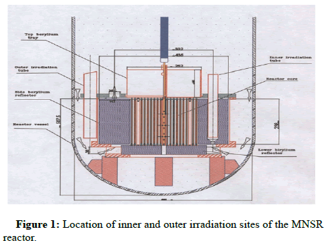

 .
.
 .
.
 .
.