Case Report, J Nucl Ene Sci Power Generat Technol Vol: 8 Issue: 2
IEC 61850 Based Electrical Protection and Control System for Nuclear Power Plants
Choong-koo Chang*
Department of Nuclear Power Plant Engineering, KEPCO International Nuclear Graduate School (KINGS), Ulsan, Korea
*Corresponding Author : Choong -koo Chang
Department of Nuclear Power Plant Engineering, KEPCO International Nuclear Graduate School (KINGS), Ulsan, Korea
E-mail: ckchang@kings.ac.kr
Received: June 22, 2019 Accepted: July 02, 2019 Published: July 09, 2019
Citation: Chang CK (2019) IEC 61850 Based Electrical Protection and Control System for Nuclear Power Plants. J Nucl Ene Sci Power Generat Technol 8:2.
Abstract
Using IEC61850 across the Low Voltage (LV) and Medium
Voltage (MV) protection systems allow the implementation of a
number of advanced features such as logic selectivity interlocking
when a short circuit occurs. In addition to improved logic selectivity
and higher overall reliability, use of a single protocol offers a
common interface for plant supervision and monitoring, providing
more and better-quality data to operators so they can run the plant
in an optimum way. This paper proposes the IEC61850
technology based electrical protection and control system for the
MV and LV networks in nuclear power plants. Current practices
are reviewed and then introduce the methodologies of how to
apply IEC61850 in the electrical protection and control systems of
nuclear power plants. Finally, the expected advantages and
challenges will be elaborated.
Keywords: IEC61850; Electrical protection and control system (EPCS); Intelligent electronic device (IED); Integrated digital protective relay (IDPR); Medium voltage (MV); Low voltage (LV) networks
Introduction
Electric power systems in power plant usually divided into 2 groups by voltage level: Medium voltage (1 KV to 100 kV) and Low Voltage (less than 1 kV) Systems. For the Medium voltage (MV) Network Integrated Digital Protective Relays (IDPR) are provided in general. The digital protective relays perform not only protection function but also control and monitoring functions for electric power systems. In addition, by the advancement of the Intelligent Electronic Device (IED) and communication technology, substation automation or distribution automation system also realized by IED type protective relays.
Traditionally, protection and control elements for low voltage (LV) systems function independently and interlock between circuits is made by hardwire in the field. But IEC61850 is now being increasingly used in LV applications, thus greatly extending its reach. IEDs utilizing IEC61850 protocol have been developed for LV circuit breakers as well as MV circuit protection recently. Together, these devices make it possible to design and operate a fully integrated protection and supervision system that spans the LV and MV networks. This comprehensive approach is possible by exploiting IEC61850 protocol to create features such as real-time diagnostics, integrated engineering, and advanced logic selectivity based on peer to peer communication, real-time diagnostics, and integrated engineering.
Overview of Existing Electrical Protection and Control System
Relays and field devices
Digitalized protective relays were applied to Class 1E and Nonclass 1E MV systems fully form the Shin-Kori Unit 3 and 4 nuclear power plants in Korea. Total four (4) types of digital relays were installed in the MV networks of APR 1400 Nuclear Power Plants (NPPs). Those are dedicated relay for generator protection, transformer protection, motor protection and feeder protection each. Each relay has all functions required for equipment protection. For the major equipment such as the main generator, main transformer and Unit Auxiliary Transformers (UATs) two out of three protection logic was applied.
The circuit voltage and current are converted into an analog signal by transduces and transmitted to the Main Control Room (MCR) via the Component Control System (CCS) and the dispatch center via the Energy Management System (EMS). Resistive temperature detectors for temperature sensing have been installed in large transformers and motors.
Distribution switchgear
Digital protective relays for the incoming feeder and outgoing feeders of the MV switchgear receive input signals form Current Transformers (CT) and Voltage Transformers (VT). It then transmit trip signal which was produced by overcurrent relays (device no. 50 and 51), ground overcurrent relays (device no. 50GS and 51G) or undervoltage relay (device no. 27) to corresponding circuit breaker.
The circuit breaker control is conducted by the local switch of the MV switchgear or by the remote control switch of the Man Machine Interface System (MMIS) located in the Main Control Room (MCR). The remote control signal is transmitted from the MCR to the switchgear via the CCS. MV motor starts and stops operation is made by the feeder breaker control circuit in the CCS.
The 480V load centers are equipped with Air Circuit Breaker (ACB). The ACB has built-in trip device composed of the current sensor, instantaneous trip element, short time trip element, and longtime trip element. In addition, instantaneous ground overcurrent relay (50GS) or time ground overcurrent relay (51G) was installed for feeders respectively.
The ACB is controlled either by the local control switch in the load center or remote control switch in the MCR or local control room by case.
Station computer system
A digital relay based electrical protection and control system (EPCS) had been installed. The EPCS consists of operator workstations, engineering work station, data communication network, printers, and digital protective relays.
Typical functions of the EPCS are as follow but circuit breaker control is out of the scope of the EPCS in the nuclear power plants:
• Status monitoring and measurement
• Alarming and annunciation
• The sequence of event tagging
• Data logging
• Trend analysis
• Fault analysis
• Data storage
• Self-diagnosis
But, all the electrical circuit breakers are controlled in the plant control systems described in Section 5.
Challenges of existing EPCS
As mentioned at the beginning of this section, digital relays have been applied to the medium voltage networks of Shin-Kori unit 3 and 4 NPPs. However, still many devices provided by the different manufacturer are used for transformers as well as LV switchgear. It results in difficulty of unification of data modeling and communication protocol. And increase the complexity of the system and inconvenience to plant design, construction, operation, and maintenance. On the other hand, Plant Control System (PCS) or CCS does not cover the fault wave records, power consumption rate and analysis, and energy management.
Physical System Architecture of IEC 61850 based EPCS
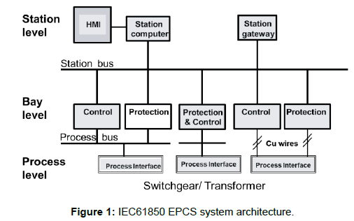
IEC 61850 is a unique international standard for substation automation and assures device interoperability. The objectives include the design of a single protocol for a complete power distribution system considering the modeling of different data required and the definition of basic services required for future proof mapping of data. The main function of EPCS can be categorized by sub-functions, which are defined as the logical nodes, and the logical nodes reside in logical devices like IEDs [1]. The IEC 61850 based EPCS is divided into process level, bay level, and station level as shown in (Figure 1).
Process and bay level
The equipment in the MV and LV power distribution systems are provided with IEDs such as IDPRs and direct trip devices. IEDs can directly communicate over a LAN, which is referred to as a process bus as shown in Figure 1. The IDPRs communicate with other devices over the LAN and have processing capabilities. Many IEDs are available currently, protective relay IEDs being the most commonly used for the automation process.
The VTs and CTs installed in the primary equipment transmit signals to a Merging Unit (MU) or to an Integrated Digital Protective Relay (IDPR). The MU is located in the power distribution system near the primary equipment.
The MU catches the sampling data, processes the data and provides them through the process bus to the protection devices. The Sampled Values (SV) are transferred as multicast messages and can be received by all the IEDs on the same communication bus. Thus multiple protection and control devices can subscribe to the broadcast voltage and current signals. Data measured at one location can also be transmitted to any subscribers through the process bus (Ethernet network). Unlike point-to-point messages, multicast messages provide the potential to develop many new protection algorithms. When it is necessary to synchronize sampled data across multiple MUs, a time signal is required to align signals from different sources [2].
The control signal from the control station reaches the field devices, for example, circuit breakers, through the process bus. In nuclear power plants, control commands are routed to the primary device via the Component Control System (CCS) by hardwire and via the process bus as a back-up path. The process bus aid in effectively communicating the information from the field instruments of the power system to the bay level more effectively and efficiently than conventional analog system [1].
The bay level is the middle level where the distributed protection and control equipment is located [3]. In the auxiliary power system of nuclear power plants Integrated Digital Protective Relays (IDPRs) are belong to bay level. Ethernet process network, MUs and field devices, and sensors belong to process level. The IDPRs and MUs are embedded in the MV switchgear and low voltage load centers.
Station level (main control room)
It consists of the monitoring part of the network and also sends commands to the IEDs for the desired network configuration. Station bus is the Ethernet switches which receives the data from the process level and IEDs in bay level and send them to other supervisory programs through the gateway and receives the commands from the operator in MCR to configure the network the way it is required [1].
The station bus is the Ethernet LAN that supports peer-to-peer communication and multiple devices and client to exchange data. The interface with another system also made in this layer. The IDPRs perform the time-critical protection functions by directly interacting on the process bus. The Man-Machine Interface (MMI) devices required to control and monitor the electrical distribution system are connected to the station bus so that the operator can get the real time data of the operations. The coordination of multiple IDPRs and also the condition monitoring of the equipment in the distribution system (transformers, circuit breakers and batteries, etc.) are managed by the station level MMIS via the station bus [3].
Software and Communication Architecture of IEC 61850 Based EPCS
Logical nodes and mapping
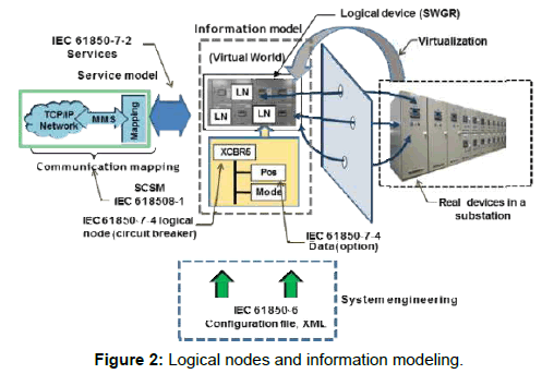
The logical nodes (LNs) represent functions or equipment used in power systems (Figure 2). Each LN provides a list of wellorganized and named information. The data model is defined in the following industrial standards [4].
• IEC 61850-7-4 Compatible logical node classes and data classes
• IEC 61850-7-3 Common data classes
The architecture of IEC61850 is extremely flexible, and it can be described very simply: IEDs such as relays implement functions required for protection and control in the form of logical nodes. Each logical node is described by an acronym (Figure 2).
MV switchgear is equipped with IDPRs for incoming and outgoing feeder breakers. Logical nodes on analog signals of switchgear (measurement/control/status) are defined as follows:
• XCBR: LN for circuit breaker
• XSWI: LN(DS, ES) for switch except for CB
• CILO: LN for interlock condition for switch control
• CSWI: LN for control of switch-like CB, DS, etc.
• GGIO: LN for general status data related to other IEDs
• MMXU: LN for Measuring (Voltage, current, frequency, etc.)
• PTOC: LN for overcurrent relay
• PTRC: LN for trip command
• GGIO: LN for general input/output
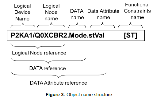
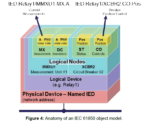
The data point is modeled but instead of an index number the logical nodes that are understandable without additional decoding aid. Naming systems are universal and easy to understand with IEC 61850 standards, Figures 3 and 4 are examples of naming.
The logical node concept is in a major role in the whole standard. The logical nodes are the basic objects that exchange information and the “backbone” to model real devices. The logical nodes contain some mandatory predefined sets of data objects with specific data attributes. All of these concepts have logical structures and strong semantics related to the actual electric power distribution devices and tasks. The information contained in logical nodes is exchanged within the protection and control system with well-defined rules and performance requirements [5].
IEC61850 provides a comprehensive model for how power distribution system devices should organize data in a manner that is consistent across all types and models of devices. As a result, the electrical device can be self-configured and do not require much tedious configuration efforts. For example, if a CT and/or VT input is connected to an IEC61850 relay, the relay can detect this module and assign it to the instrumentation unit automatically without user interaction.
Some devices use a Subject Configuration Language (SCL) file to configure the object, so the engineer only imports the SCL file into the device to configure it. The IEC61850 client application can then extract object definitions from the device over the communications network. As a result, the cost and effort involved in configuring IEC61850 devices are greatly reduced [5].
Communication structure
The EPCS is used as the fault protection and analysis of the electrical system, and the backup for the process control system. It consists of various devices, such as main transformer protection relays, unit auxiliary transformer protection relays, auxiliary power distribution system protection relays, fault recording devices, highspeed bus transfer switching devices, synchronizer, DC system protection relays, and UPS protection systems. Therefore a large amount of protocol converters are required. Consequently, communication speed is lowered and system stability is also decreased. The solution to this problem is to use protection and automation devices that fully compliant with the IEC 61850 standard in the entire plant. The ability to share information between devices from other manufacturers greatly increases site communication reliability and reduces maintenance workforce [6].
All communications use Ethernet (ISO/IEC 8802-3) as the default communication technology. Services commonly used for communications within a full power system are mapped in IEC 61850-8-1 to Manufacturing Message Specification (ISO 9506). MMS is an application layer standard designed for the messaging communications between IEDs in a distributed system environment.
The MMS was selected because it is the only public standard protocol that can easily support the Abstract Communication System Interface (ACSI) mapping and information model defined in IEC 61850-7-X series [7]. The IEC 61850 standard is conceptually developed to be independent of the conventional concept of communication media and message transmission. Of these, specific communication profiles have been decided and generally used. The actual decision is for
• Ethernet as the media
• TCP/IP
• ISO session and presentation layer
• MMS (Manufacturing Message Specification (ISO 9506-1 and ISO 9506-2)
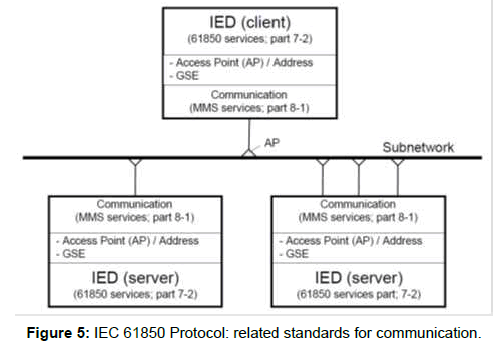
The IEC 61850 standard describes the services requested by the Abstract Communication System Interface (ACSI) included in part 7-2 of the standard. The mapping to MMS for all aspects of service and Ethernet use is specified in Part 8-1 of IEC 61850. Each device manufacturer that is a partner in an IEC 61850-based communications network must compile with both specifications, and adapt the product to meet the requirements and definitions outlined in the standard (Figure 5).
The Protocol Implementation Conformance Statement (PICS) document is defined to make this profile visible to all other partners, so they can check what they can expect and what they have to support. The PICS contains in a table based form the possibility of a product or product family [8].
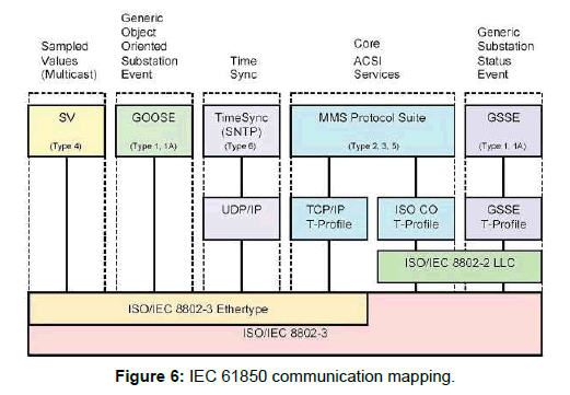
Additional protocols are defined for ACSI services that are not mapped to MMS, for example, Simple Network Time Protocol (SNTP) for time synchronization messages or Generic Object- Oriented Substation Events (GOOSE) and General Substation Status Events (GSSE) for trip signals and fast message. An overview of all these mappings used for the standard IEC 61850 (Figure 6).
Interface with Process Component Control System
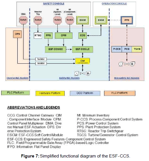
Process systems of a nuclear power plant are divided into safetyrelated systems and non-safety related systems. The safety-related systems are controlled by the Engineered Safety Features- Component Control system (ESF-CCS) and non-safety related systems are controlled by a Power Control System (PCS) or Process-Component Control System (P-CCS).
The ESF-CCS provides discrete and continuous control of the nuclear safety-related systems as well as automatic or manual actuation of the ESF systems components. The ESF-CCS controls circuit breaker operated components (e.g., pumps, fans, heaters, motor-operated valves), solenoid operated components (e.g., pneumatic, electro-pneumatic, direct-operated valves), and control valves. The ESF-CCS also controls continuous control devices such as modulating valves. The simplified functional diagram of the component control system (Figure 7) [9]. Circuit breakers are used to control most of the loads rated at 480Vac and above.
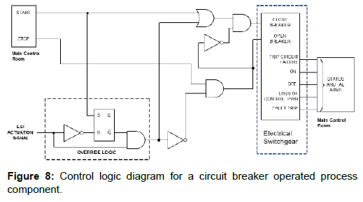
Figure 8 is a Control Logic Diagram (CLD) showing the generic control logic required to energize the breaker closing circuit and the breaker trip circuit. The protection, monitoring, and management of electrical apparatus, such as main transformer, Unit Auxiliary Transformer (UAT), and Standby Auxiliary Transformers (SAT) are conducted by IEC 61850 based Electrical Protection and Control System (EPCS). The EPCS is responsible for the electrical protection and monitoring of the MV switchgears and the LV load centers too.
The incoming circuit breakers of MV and LV switchgear and branch feeder circuit breakers for the process components are controlled by the component control systems (ESF-CCS, P-CCS or PCS). And, the EPCS is used as a backup of process components power supply control, and in the meanwhile, it provides monitoring, management and fault analysis functions.
All the protection and monitoring relays in the bay level are installed in the local switchgear cubicles. Relaying and metering panels for transformers are installed in the equipment room beside the main control room.
Large-capacity transformers, such as main transformer and unit auxiliary transformers are installed outdoors and are far from relay and metering panel, so the control cable length is significantly long and the mechanical protection and control cables connecting the field instruments and relay and metering panel are also long. In particular, the Merging Unit (MU) can be applied to these locations to facilitate cable construction while reducing errors in protection and control signals due to long-distance control cables.
Conclusion
The up to date EPCS requires digital communication for the efficient operation of electric power distribution systems for nuclear power plants. However, several or more manufacturers provide relays, measuring and control instruments for the auxiliary power systems of nuclear power plants. The result is not only a lack of integrated data modeling and communication protocols, but also many side effects such as reduced communication speed, and reliability, increased system complexity, and inconvenience in plant design, construction, operation, and maintenance.
As described in Section 3 to 5, by implementing the IEC 61850 international standard the protocol conversion between devices produced by the different manufacturer is not required. Communications between protection and monitoring devices are achieved by GOOSE and SV network. Monitoring, maintenance, and management are convenient and cable wiring is simple. In addition, the optimized system layout is possible too.
On the other hand, IEC61850 based EPCS can utilize many of useful control functions for both MV and LV networks. By coordination between feeder protection relays the EPCS be able to perform high-speed bus transfer. Zone selective interlocking by the peer to peer communication function of IEC61850 protocol can prevent the short circuit fault propagation in the LV systems and function like bus differential protection relay without additional CTs in the system. Information is shared between devices and thus reciprocal interlocking becomes available.
The IEC61850 based EPCS can control process components and be used as backups of ESF-CCS, P-CCS, and PCS system. Currently, the EPCS system performs only electrical protection and monitoring, but the application of the IEC 61850 protocol allows to control the circuit breaker more effectively. However, software verification and validation are essential for implementing IEC61850 based EPCS to safety-related electrical systems.
Acknowledgment
This research was supported by the 2019 Research Fund of the KEPCO International Nuclear Graduate School (KINGS).
References
- Thomas MS, McDonald JD (2015) Power system SCADA and smart grids. CRC Press. 110: 1-335.
- Chen X, Crossley PA, Guo H (2014) design, construction and validation of a next generation protection and control system based on IEC61850 standards, proceeding of the 12th IET International Conference on Developments in Power System Protection. pp: 1-6.
- Roostaee S, Hooshmand R, Ataei M (2011) Substation automation system using IEC 61850, Proceeding of the 5th International Power Engineering and Optimization Conference Year. pp: 393-397.
- Gholizadeh N (2016) IEC 61850 Standard and its capabilities in protection systems, Politechnico Di Milano, Master Dissertation, pp: 35-36.
- ABB Group (2011) IEC 61850 Communication Protocol Manual, Sweden. pp: 45.
- Baigent D, Adamaik M, Mackiewicz R (2009) IEC 61850 communication networks and systems in substations: An overview for users. The Protection and Control Journal. pp: 61-68.
- Hou W, Yang Y, Yan W, Zhang C (2014) Solutions of electrical control and management system for thermal power plant based on IEC61850, Proceeding of the 2nd IEEE Conference on Power Engineering and Renewable Energy (ICPERE). pp: 199.
- Lloret P, Velasquez JL, Molas-Balada L, Villafafila R, Sumper A, et al. (2007) IEC 61850 as a flexible tool for electrical systems monitoring, Proceeding of the 9th International Conference on Electrical Power Quality and Utilisation. pp: 3.
- Korea Electric Power Corporation and Korea Hydro and Nuclear Power Co., Ltd. (2014) APR1400 Design Control Document Tier 2. 7: 3-67.
 Spanish
  Chinese
  Russian
  German
  French
  Japanese
  Portuguese
  Hindi
Hindi 