Research Article, J Fashion Technol Textile Eng S Vol: 0 Issue: 4
Influence of Stripping Solution’s Concentration on the Seebeck Coefficient of Nickel-Coated Carbon Fibers
Hardianto A1,2*, Hertleer C2, De Mey G3 and Van Langenhove L2
1Polytechnic of Textile Technology (Politeknik STTT Bandung), Jalan Jakarta 31, Bandung 40272, Indonesia
2Ghent University, Department of Materials, Textiles and Chemical Engineering, Technologiepark 907, 9052 Zwijnaarde, Belgium
3Ghent University, Department of Electronics and Information Systems, Technologiepark 15, 9052 Zwijnaarde, Belgium
*Corresponding Author : Anto Hardianto
Polytechnic of Textile Technology (Politeknik STTT Bandung), Jalan Jakarta 31, Bandung 40272, Indonesia
Tel: +09 264 58 30
E-mail: hardianto@kemenperin.go.id
Received: December 01, 2017 Accepted: February 21, 2018 Published: February 27, 2018
Citation: Hardianto A, Hertleer C, De Mey G, Van Langenhove L (2018) Influence of Stripping Solution’s Concentration on the Seebeck Coefficient of Nickel- Coated Carbon Fibers. J Fashion Technol Textile Eng S4:008. doi:10.4172/2329-9568.S4-008
Abstract
Sensors and actuators made out of textile materials are the subjects of many research activities, especially because of the specific properties possessed by the textiles. In this context, yarns with a different Seebeck coefficient can be applied for making a textilebased thermopile. Preliminary experiments have shown that a pair
of nickel-coated carbon fibers (NiCF) and carbon fibers (CF) has a good Seebeck coefficient. In this paper, we study the influence of the concentration of the solution used to strip off the Ni from the NiCF. Experiments show that a mixture of 37% HCl and 10% H2O2 (1:1) result in the highest Seebeck coefficient.
Keywords: Thermopile; Stripping process; Seebeck coefficient; Conductive yarn
Introduction
Metal wires are widely used in the field of smart textiles as electrically conductive tracks, heating pads, EMI shieldings, conductive fabrics, thermocouples and other purposes. The following are some of the reported papers where metal wires were used as thermocouple/thermopile. Thermal flowmeters or heat flux sensors made from a copper-coated constantan wire when processed becomes a thermopile have been reported by several authors [1-4]. A textile-based temperature sensing device made with a Type T thermocouple from two metal wires inserted into woven and knitted fabrics has been investigated [5]. Due to the lack of flexibility of the metallic wires, researchers also studied the use of organic conductive polymers i.e. Poly (3,4- ethylene dioxythiophene): poly(4styrenesulfonate) (PEDOT:PSS) and polyaniline (PANI) which were screen printed onto woven fabrics to make a thermocouple [6].
Currently, various conductive textile yarns are available in the market. Our focus is to apply these yarns to make a thermopile because they are more flexible than metallic wires. A thermopile consists of many thermocouples arranged in series or parallel. From our preliminary study [7], we have concluded that the nickel from nickel-coated carbon fiber can be removed by the combination of hydrochloric acid and peroxide. But, we still don’t know the optimum concentration of peroxide for this process. So, we need to know the effect of peroxide’s concentration up to 20%. Accordingly, if we can make lots of Nickel/Carbon junctions along the yarn by selectively removing the Ni from the NiCF yarn, we assume that a textile-based thermopile can be created.
In this paper, we report the influence of the concentration of the stripping solution containing H2O2 and HCl on the Seebeck coefficient of nickel-coated carbon fibers and conclude on the optimal concentration.
Materials and Methods
Material
In this work, we have started from commercially available nickelcoated carbon fiber (NiCF) yarn purchased from Toho Tenax Europe GmbH, Germany (Tenax-J HTS40 A23 12K 1420tex MC) which consists of 12000 filaments and has a linear mass density of 1420 tex.
Stripping process
Mixtures of hydrochloric acid/HCl (Sigma-Aldrich) and hydrogen peroxide/H2O2 (Chem Lab) were used as stripping solution to remove the nickel from the NiCF yarn. The stripping process was done according to our previous work [7]. The experiments were done under a laboratory fume hood with proper exhaust ventilation. The concentration of H2O2 was varied from 3% up to 20% while the HCl was held constant. HCl and H2O2 were mixed with the same ratio (1:1). Chemicals and conditions of the stripping process of NiCF can be seen in Table 1. NiCF samples were immersed in a glass beaker containing HCl and H2O2 for 30 minutes without additional heating treatment, then the samples were rinsed with running water and the remaining water on the samples was absorbed by blotting paper. Finally, the samples were air dried at room temperature for at least 24 hours before use.
Table 1: Chemicals and conditions of the stripping process of NiCF.
Seebeck coefficient measurement
A nano voltmeter Amplificator NV 724 from Setaram, Lyon, France was used to measure the voltage between treated NiCF and untreated NiCF. A hot plate “Isotemp” from Fisher Scientific was used to heat the thermocouple junction of the samples. To avoid the thermocouple junction touching any electrical conductors, a piece of paper was placed on top of the hot plate. A weight from wood material was placed on top of the junction to fix its position. The other ends of the samples were connected to the Nanovoltmeter. Temperature near the junction was measured with a digital thermometer Fluke 52. A schematic diagram of Seebeck coefficient measurement setup is shown in Figure 1.
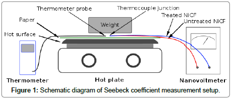
Figure 1: Schematic diagram of Seebeck coefficient measurement setup.
The Seebeck coefficient S (μV/°C) was obtained from the slope of the linear graph of voltage vs. temperature of the pair of treated NiCF and untreated NiCF. During the measurement, the temperature was varied between 3°C and 51°C, which mimics the temperature profile near the human skin. The voltage was measured from 51°C to 3°C during the cooling down of the hot plate. This measurement was repeated five times for each sample.
Results and Discussion
In this paper, we have studied the influence of the stripping solution’s concentration on the Seebeck coefficient of the stripped NiCF against the untreated NiCF. This study is useful to determine which concentration of stripping solution will give the highest Seebeck coefficient between the treated NiCF and the untreated NiCF.
In this study, we have varied the concentration of peroxide such as follows: 3%, 6%, 10%, 15% and 20%, while the concentration of hydrochloric acid was held constant at 37%. Both chemicals were mixed in the same ratio (1:1). We used heat resistant glass beakers in the stripping process because it generated heat during the reaction process. This phenomenon was typically an exothermic reaction that made the stripping solution very hot. That was the reason that additional heating treatment was unnecessary during the stripping process. Although the hydrochloric acid is not too concentrated, it is recommended to prepare the peroxide solution first in the glass beaker and then add the hydrochloric acid solution into it through the glass wall of the beaker to prevent sudden splashing. Then the glass beaker was shaken to mix the two chemicals. After the solution was well mixed, the NiCF sample was immersed in the mixture. Initially, the mixture was not too hot but its temperature was gradually increasing during the stripping process and then until at one point the temperature of the solution was decreasing and became cooler.
While using the 15% and 20% H2O2 and 37% HCl (1:1) mixture to strip nickel from NiCF, there was an interesting phenomenon i.e. soon after immersing the NiCF into the solution, it became very hot and produced lots of hissing bubbles that were increasingly rising up from the solution into the air above the surface of the solution and then gradually subsided and disappeared. Actually, bubbling also happened when using the 3%, 6% and 10% H2O2 and 37% HCl (1:1) mixture, but the 20% H2O2 + 37% HCl (1:1) mixture was the most extreme one. Therefore these experiments must be done under a laboratory fume hood with proper exhaust ventilation. In this process, the nickel on the surface of the NiCF was oxidized in the stripping solution to form nickel chloride as indicated by green coloured solution at the end of the process. The reaction can be expressed such as follow:

Figure 2 shows the graph of voltage versus junction temperature taken from the average value of five measured Seebeck coefficients. From this graph, we can see that the relation between the temperature and voltage is linear. Generally, the graph shows that the higher the concentration of the stripping solution, higher the slope of the linear graph. Since the Seebeck coefficient is taken from the slope of the graph, this also means that the higher the concentration of the stripping solution, the higher the Seebeck coefficient as can be seen in in Figure 3.
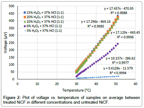
Figure 2: Plot of voltage vs. temperature of samples on average between treated NiCF in different concentrations and untreated NiCF.
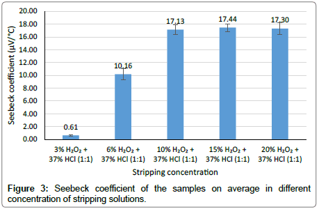
Figure 3: Seebeck coefficient of the samples on average in different concentration of stripping solutions.
The pair of untreated NiCF and stripped NiCF samples with 15% H2O2 and 37% HCl (1:1) gives the highest Seebeck coefficient (17.44 μV/°C). From the graph in Figure 3, we can see that the Seebeck coefficients resulted in the sample stripped with 10%, 15% and 20% H2O2 (each mixed with 37% HCl in the same ratio (1:1)) seem to be the same. If we compare this value to the Seebeck coefficient of metal wire-based thermocouple from chromel and platinum (22.2 μV/°C) [8], NiCF has a good potential as a textile-based thermocouple.
This result also tells us that as the concentration of peroxide is increasing, the more nickel can be removed from the surface of NiCF. Therefore, the concentration of peroxide influences the removal of nickel from NiCF which in turn will influence the Seebeck coefficient between the treated NiCF and the untreated NiCF. When the nickel layer disappears from the surface of the carbon fiber (NiCF), theoretically the NiCF filament will return to the single material i.e. carbon fiber and it changes its electrical properties. Thus, we can get higher Seebeck coefficient while using the NiCF treated in a higher concentration of peroxide, indicating a higher amount of nickel removal from the carbon fiber surface.
From this experiment, we choose the mixture of 10% H2O2 and 37% HCl (1:1) to strip NiCF filament because it is sufficient for this purpose compared to the solution with 15% and 20% peroxide which produce very hot solution and lots of hissing bubbles where the gases are released into the air during the stripping process.
Conclusion
After stripping the NiCF samples in different concentration of peroxides, it can be concluded that the higher the concentration of the stripping solution, higher the Seebeck coefficient. The 10% H2O2 and 37% HCl (1:1) is sufficient to be used to strip the nickel-coated carbon fiber to obtain a good Seebeck coefficient value between the treated NiCF and the untreated NiCF. Future work is to use this stripping solution to etch the NiCF locally to make a thermopile from NiCF filament in fabric structures.
Acknowledgement
Mr. Hardianto would like to thank the Indonesian Endowment Fund for Education (LPDP) for making this work possible by financially supporting his research activities.
References
- Dupont D, Godts P, Leclercq D (2006) Design of Textile Heat Flowmeter Combining Evaporation Phenomena. Text Res J 76: 772–776.
- Codau TC, Onofrei E, Bedek G, Dupont D, Cochrane C (2015) Embedded textile heat flow sensor characterization and application. Sensors Actuators A Phys 235: 131–139.
- Gidik H, Bedek G, Dupont D, Codau C (2015) Impact of the textile substrate on the heat transfer of a textile heat flux sensor. Sensors Actuators A Phys 230: 25–32.
- Hertleer C, Bedek G, Dupont D (2015) A Textile-Based Heat Flux Sensor, Dokuz Eylül University Textile Engineering Department, Izmir, Turkey.
- Alexander R. Jones (2011) The Application of Temperature Sensors Into Fabric Substrates.
- Seeberg TM, Royset A, Jahren S, Strisland F (2011) Printed organic conductive polymers thermocouples in textile and smart clothing applications.
- Hardianto A, Hertleer C, De Mey G, Van Langenhove L (2017) Removing nickel from nickel-coated carbon fibers.
- Bentley RE (1998) Handbook of Temperature Measurement Vol. 3: The Theory and Practice of Thermoelectric Thermometry. Springer, Germany.
 Spanish
  Chinese
  Russian
  German
  French
  Japanese
  Portuguese
  Hindi
Hindi 
