Spanish
  Chinese
  Russian
  German
  French
  Japanese
  Portuguese
  Hindi
Hindi Research Article, J Nucl Ene Sci Power Generat Technol Vol: 14 Issue: 1
Numerical Analysis of the Thermohydraulic Effects of Swirl-type Mixing Vanes in Pressurized Water Small Modular Reactor Core in Single-Phase Condition
Shanyan Najafzadeh and Mohammad Nazififard*
1 Department of Energy Systems Engineering, School of Mechanical Engineering, University of Kashan, Kashan, Iran
*Corresponding Author: Mohammad Nazififard
Department of Energy Systems Engineering, University of Kashan, Kashan, Iran
Tel: 983155912888
E-mail: nazifi@kashanu.ac.ir
Received date: 29 July, 2023, Manuscript No. JNPGT-23-108458; Editor assigned date: 02 August, 2023, PreQC No. JNPGT-23-108458 (PQ); Reviewed date: 16 August, 2023, QC No. JNPGT-23-108458; Revised date: 22 January, 2025, Manuscript No. JNPGT-23-108458 (R); Published date: 29 January, 2025, DOI: 10.4172/2325-9809.1000433
Citation: Najafzadeh S, Nazififard M (2025) Numerical Analysis of the Thermohydraulic Effects of Swirl-type Mixing Vanes in Pressurized Water Small Modular Reactor Core in Single-Phase Condition. J Nucl Ene Sci Power Generat Technol 14:1.
Abstract
Small Modular Reactors (SMRs) produce power in the range of 100 to 300 megawatts, which is less compared to power reactors. Typically, the cores of these reactors are smaller in size than power reactors, and power generation equipment are placed inside the reactor vessel. SMRs have several types, the most common being the pressurized water SMRs. Basically, in a pressurized water reactor, the most important constraint for heat generation is the heat disposal from the reactor core fuel rods. The mixing vanes attached to the spacer grids of the fuel assemblies enhance heat disposal from the reactor core. In this numerical study, Computational Fluid Dynamics (CFD) and sub-channel approach are used to simulate fluid flow and investigate the effect of swirl-type mixing vanes in the reactor core. Single-phase fluid flow equations are solved using the k-ε turbulence model by ANSYS CFX 18. The model is validated using available experimental data in a 2 × 2 rod bundle array and there is an acceptable 9% difference between numerical results and experimental data. Simulations are analyzed with and without the presence of swirl-type mixing vanes in the computational domain in different Reynolds numbers, which correspond to different mass flow inlets. Results reveal that swirl-type mixing vanes increase turbulence by making secondary flows in the lateral direction. These vanes can be used to decrease the average temperature of fuel rods surfaces by 1.75°C and raise the generated power level by 19.8%. However, the core pressure drop and pumping costs rises reasonably.
Keywords: Small modular reactor; Swirl-type mixing vane; Sub-channel; Computational fluid dynamics
The increase in the world's population, the reduction, and loss of fossil fuels, as well as the pollution caused by them, have created limitations for the future of mankind. Given these limitations, the proper and efficient use of energy resources, especially the use of renewable energies, can eliminate the problems that are related to the energy field. In this regard nuclear energy, though not considered renewable, is considered a clean energy resource and has received much attention. Today, with increasing energy consumption, the world has faced two crises of environmental pollution due to the use of fossil fuels and the reduction of fossil fuel resources. Therefore, nuclear reactors with less harmful effects on the environment have become more and more of a concern in different industrialized countries and play an important and vital role in addressing the increasing need for energy in the world, as well as responding to the challenges associated with environmental impacts and global climate. On this subject, power reactors and small modular reactors are commonly used to generate power and use nuclear energy in response to worldwide demand. Small modular reactors have simpler, easier and standard modular design. These reactors are constructed in the factory and need less initial investment and less construction time. These reactors can be small enough to provide portability and also to be used in remote areas without infrastructure or power grids. In the range of less than 300 MW, these reactors are a good choice to meet the needs of energy in different countries. These reactors can also be used to generate power in areas with high population. These reactors are suitable for power supply in countries with small and limited distribution systems, large distribution systems and countries with small and limited financial resources to invest in nuclear power plants. Most of the proposed designs for small modular water reactors propose the cogeneration of electric power and heat for industrial complexes. Other benefits of these reactors over conventional power reactors include following items:
• Longer life cycle and less need for refueling (every 10 to 15 years).
• Greater safety because of being small and modular.
• More options for positioning these reactors.
• Less ground area needed for these power plants.
• Lower maintenance costs.
• Lower initial cost and risk.
• Applicable for distributed generation policies.
• Cogeneration of power, heat and also cooling.
Examples of such reactors are SMART Korean reactor, Russian VBER and KLT reactors, NUSCALE, Westinghouse and mPower American reactors [1-3].
Spacer grids, or briefly spacers, are important components used to maintain fuel rods and keep the distance between them constant in the fuel assemblies. They also avoid flow-induced vibrations damages that might harm fuel rods and create vortex downstream of the grid area. This vortex is created by mixing vanes attached to the spacer grids. Mixing vanes have different geometries with different bending angles which correspond to different blockage ratios. These vanes are installed at the spacer outlet and cause turbulence. Turbulence causes secondary flows, improves thermal mixing and raise local pressure drop. Basically, mixing vanes are similar in power reactors and SMRs, but due to the lower power output of SMRs and other design considerations associated with these reactors, fuel rods length in SMRs are usually shorter than that of power reactors and fewer spacer grids are used in SMRs fuel assembly. Therefore, it is necessary to study thermohydraulic effects of mixing vanes in the core of SMRs as well as those of power reactors.
Generally, previous studies have investigated the effects of using different mixing vanes in the core of power reactors. In this study, we have analyzed effects of swirl-type mixing vanes on the thermohydraulic characteristics of SMRs core.
Materials and Methods
Researchers have made great efforts for numerical analysis of thermohydraulic effects of mixing vanes in reactor core. Karouta, et al. analyzed 3D fluid flow using CFD to design a spacer grid of a pressurized water power reactor [4]. They used experimental data of the velocity field for the model validation. They also used the subchannel approach, which is also proposed by Todreas and Kazimi, because the reactor core consists of symmetric geometry and a simple subchannel can be used for analysis instead of a full channel [5]. After validating the simulation results, they investigated different spacer grids and concluded that the CFD model can be useful in optimizing spacer grid designs and analysis of flow downstream the spacer grid. They also concluded that the intensity of the vortices created by grids can be a quantitative measure for the effect of the spacer grid on improving the heat transfer. A numerical CFD model was investigated for optimal design of mixing vanes for use in a pressurized water reactor fuel assembly by In, et al. [6]. In their study, three types of mixing vane with different geometries and bending angles relative to the axis were investigated. Computational domain in their study included a span of the reactor core, which is an axial symmetric domain and is repeated along the axis. Symmetry boundary condition was used to analyze a span in order to reduce computational cost. Finally, it was concluded that in the given geometry and operating conditions, the optimal design was for swirl-type mixing vanes with a 40-degree bending angle. Seo, et al. investigated the swirl created by different mixing vanes to improve heat transfer and increase the safety margin of pressurized water reactors [7]. This increase in the safety margin is proportional to the increase in the critical heat flux value in pressurized water reactors, corresponding to the phenomenon of departure from nucleate boiling. This increase reduces the likelihood of an accident occurring and increases the safety margin. In their study, after experimental examining of the velocity field using particle imaging velocimetry, numerical models were developed and validated using experimental data. Finally, it was concluded that by increasing the intensity of the vortices created by the mixing vanes, the safety margin of the reactor core heat transfer improves. An innovative design with rotating vanes is also presented in their study for the spacer grid of pressurized water reactors. Sohag, et al. investigated the forced convection flow using a numerical analysis in a computational domain comprising one-eighth of a 3 × 3 subchannel with considering 9 fuel rods in square arrangement in their analysis [8]. Simulations were performed with and without the presence of spacer grids, and the results showed that increasing the blockage ratio improves the heat transfer, although the pressure drop of the fuel assembly rises. In 2008, Nematollahi and Nazifi studied different types of mixing vanes using CFD and concluded that despite the difficulties of making split-type mixing vanes and the raise they cause in pumping costs, these mixing vanes can improve the overall heat transfer of the fuel assembly by up to 9.8% [9].
Great effort has also been made to choose the appropriate turbulence model for CFD analysis of reactor in previous studies. Liu, et al. simulated fluid flow in a pressurized water reactor fuel assembly using CFD [10]. In their study, the performance of different turbulence models is evaluated based on Nusselt number distribution in fuel assemblies. The results showed that in the presence of spacer grids, the k-ε turbulence model yields acceptable results. Podila, et al.
validated their simulations using the k-ε turbulence model and experimental data of the velocity field of a 5 × 5 fuel assembly [11]. Cinosi, et al. also investigated the use of different turbulence models by numerical analysis of the flow field [12]. In their study the same experimental data with Podila, et al. study was used involving the Spacer grid with mixing vanes and the k-ε model was proposed.
Available studies show that most of the work done in the field of numerical analysis of the thermohydraulic effect of mixing vanes is related to the single-phase flow field in the core of pressurized water reactors. Although SMRs are new under-development generation of nuclear reactors, less attention has been paid to the thermohydraulic analysis of the core of these reactors. Besides, considering the size of SMRs, which are smaller than that of pressurized water reactors, investigation of the application of newly innovated components in the core of these reactors is the matter of great importance. In the present study, using a CFD tool, single-phase flow field governing equations in the core of a small pressurized modular water reactor is solved. The sub-channel approach is used for bare sub-channel (without vaned spacer grid) and vaned sub-channel (with vaned spacer grid). Simulations are performed in different Reynolds numbers and the results related to the effects of swirl-type mixing vanes on the thermohydraulic characteristics of the flow field are presented. The equations governing the flow field and the results are presented below.
Governing equations
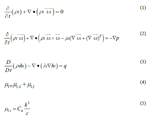
Basically, water flow should be single-phase in a pressurized water reactor to remove heat from the fuel rods under normal operating condition. In this study, Reynolds-averaged Naiver–Stokes equations, which include mass (1), momentum (2), and energy (3) equations, together with the k-ε turbulence model (4,5) are used for the analysis. More details on this model are available in reference [13]. The following equations have been solved numerically using ANSYS CFX 18 software.
Validation of the computational model
To validate the solution method, it is first compared with the existing experimental data. For this purpose, the experimental data provided by Karouta, et al. is used to validate the single-phase solution method. This data includes velocity distributions that are investigated by the Laser Doppler Velocimetry (LDV) tool. The validation in this study involves comparing the simulated velocity distribution with the velocity distribution of the test data.
Also, to select the appropriate turbulence model in this study, different turbulence models have been implemented on the data of this section. The computational domain, boundary conditions, geometry details as well as the lines for measuring velocity at different distances downstream of the spacer grid are shown in Figure 1.

Figure 1: Sub-channel analyzed for the validation and its details including boundary conditions, LDV lines and geometry details
In Figures 2-4 the normalized velocity distributions obtained from the simulation at different cross-sections for the geometry and boundary conditions shown in Figure 1 are compared with the experimental normalized velocity distributions obtained by LDV tool. These cross-sections were located at 1.2, 15.8 and 38.5 times the hydraulic diameter downstream of the spacer grid, respectively. The inlet velocity is 6.79 m/s and this value is used to normalize the velocity distribution at different cross-sections. Outlet relative pressure is also considered zero to perform simulations. The velocity field is also fully-developed upstream of the Spacer grid. Various turbulence models are used in this study. As shown in three following figures, the quantity and quality of the normalized velocity distribution obtained from numerical simulation have an acceptable similarity with the quantity and quality of the normalized experimental velocity distribution data. This indicates the validity of the method used in numerical simulation. Equation 6 is used to measure the error, or in other words, the difference between the results of the simulation using the k-ε turbulence model and the experimental results.

In equation 6 N is equivalent to the number of points where LDV measurement was performed. Using this equation, the average difference between the numerical and experimental results is 9%. The discrepancy in results could be due to computational domain discretization, uncertainties in material properties, application of numerical models, very slight differences in geometry, or uncertainties associated with experimental measurements. Also, according to previous studies in this field, the cost of calculation and difference between experimental and numerical results, the k-ε turbulence model is used for further simulations in this study.

Figure 2: Comparison of cross-sectional velocity distribution at 2.1 times the hydraulic diameter downstream the spacer grid between experimental and numerical results

Figure 3: Comparison of cross-sectional velocity distribution at 15.8 times the hydraulic diameter downstream the spacer grid between experimental and numerical results

Figure 4: Comparison of cross-sectional velocity distribution at 15.8 times the hydraulic diameter downstream the spacer grid between experimental and numerical results.
Computational domain of small modular pressurized water reactor
In this study, using sub-channel approach and CFD, two different sub-channels from the core of a small modular pressurized water reactor are analyzed, one of them with and the other without the presence of vaned spacer grid. Reactor fuel assemblies are similar to those used in conventional pressurized water reactors, which are also used in SMART reactor. The diameter of the fuel rods is 9.5 mm and the pitch or center-to-center distance of the fuel rods is 12.56 mm with square configuration. Boundary conditions and other details are almost the same as those used in SMART reactor. The active length of the fuel rod is 2 m and the entrance length for flow development is 100 mm. The entrance length is about half that of conventional pressurized water reactors which have an active fuel rod length of about 4 m. The output length of the reactor core is also assumed to be 100 mm after the active length. The inlet flow boundary condition is assumed to be INLET, perpendicular to the inlet plane at a velocity of 5 m/s and a turbulence intensity of 5% at a temperature 297.7°C. Thermohydraulic effects of mixing vanes in different Reynolds numbers, different inlet mass flow rates corresponding to velocities 4, 4.5, 5.5 and 6 m/s have also been investigated. The outlet boundary condition is assumed at the outlet. At this boundary, the relative pressure is equal to zero Pascal. The operating pressure of the reactor core is also considered to be 15 MPa. The heat flux of the wall surface follows the cosine distribution. This heat is equivalent to 20 kW per fuel rod. Also in this study, after examining different two-equation models, the k-ε model is used to model the turbulence. The distance between two consecutive vaned grids in this study is 512 mm. At the outlet of the spacer grids, swirl-type mixing vanes are designed with a 30 degree bending angle. Details of the computational domain, boundary conditions, and swirltype mixing vanes are shown in Figure 5. The presented model is compared with that used in previous studies and is highly recommended by authors. High resolution advection scheme and first order turbulence numeric are applied to element-based finite volume method used in this study. Time scale control and time scale factor are set to auto and one respectively and length scale is set to conservative. To terminate the solution, reduction of residuals to 10-3-10-4 is set as criteria, which needs approximately 2000-5000 iterations. Double precision runs with intel MPI local parallel mode and 5 partitions are defined to solve the Reynolds-averaged Naiver-Stokes equations together with 2 equation k-ε turbulence model.

Figure 5: Computational domain, bare and vaned sub-channels, heat flux profile and geometry details in the present study (dimensions in mm).
Mesh independency study
To investigate the independency of the calculations from the grid, the velocity distribution is measured at a cross-section by the distance of 1.5 m from the inlet at 5 m/s inlet velocity case. These grids have different number of nodes and elements, considering at least 40% difference in these numbers for a grid from other grids, and meshing techniques such as sizing and inflation is implemented. Figure 6 shows the velocity distribution in the bare sub-channel. The vaned subchannel velocity distribution is also shown in Figure 7. Finally, according to the computational cost and velocity distribution results, M2 grid with 1288822 nodes for bare sub-channel and M4 grid with 1973483 nodes for the vaned sub-channel are selected to perform simulations. Results of these grids are less than 5% different from those of other grids. Selected grids also have acceptable quality considering skewness and aspect ratio of these grids. Figures 8 and 9 show pictures of the selected mesh. As shown in Figure 9, the more compact mesh is used in the spacer grid area.

Figure 6: Velocity distribution for different grids in bare subchannel.

Figure 7: Velocity distribution for different grids in vaned subchannel

Figure 8: Images of the computational grid used to investigate the bare sub-channel

Figure 9: Images of the computational grid used to investigate the vaned sub-channel.
Results and Discussion
To perform Nusselt number calculations, which is a good criterion for heat transfer evaluation, firstly the temperature distribution of the bare sub-channel center for different inlet flows corresponding to different Reynolds numbers (based on the hydraulic diameter of the cross-section) is investigated. This temperature distribution is shown in Figure 10. As it is evident at the initial 100 mm, the fluid temperature does not increase due to the absence of wall heat flux.
After this length, as the wall heat flux increases, the temperature in the center of the sub-channel increases from 295.7°C with an increasing slope and its maximum slope occurs at an axial position of 1.1 m. From this point onwards, the temperature rises again due to the wall heat flux, but this is accompanied by a downward slope, which means that the temperature increases along the axis with a decreasing slope. This corresponds to the cosine distribution of heat flux for the wall. Finally, the fluid temperature reaches its maximum value at the axial position 2.1 m. After this point, due to the absence of heat flux on the fuel rod wall (100 mm outlet length), the fluid temperature remains the same. Another point about the distribution of fluid temperature along the axis is the reduction of temperature increase by increasing the Reynolds number or increasing flow inlet velocity. This is due to the less time available for the fluid to transfer heat in a steady-state condition. Because with increasing fluid velocity, the time that the coolant is exposed to heat transfer decreases and leaves the subchannel faster.

Figure 10: Axial cooling fluid temperature distribution for bare sub-channel.
Figure 11 shows the Nusselt number calculated based on the numerical solution results according to the equation 7 and the Nusselt number obtained from the Wiseman correlation according to equation 8 [14]. As the graph shows, the Nusselt number rises with the increase in the Reynolds number and there is an acceptable agreement between the numerical solution results and the Weismann correlation. It can also be concluded that decrease in exposure time is dominant to the increase in heat transfer coefficient and outlet temperature decreases with increasing Reynolds number.


Figure 11: Nusselt number for bare sub-channel
The difference between numerical and correlation results in Figure 11 is mainly because of uncertainties in experimental data, using average values, using cosine profile for heat flux and contact resistance between coolant and wall and it has an acceptable value [15]. To investigate the effect of the spacer grid with swirl type mixing vanes on the heat transfer, a local increase in the Nusselt number corresponding to a local increase in the heat transfer coefficient in the sub-channel is shown in Figure 12. To investigate this, the average value of the heat transfer coefficient at the top edge of vaned spacer grids and its corresponding Nusselt number for different Reynolds numbers are extracted from numerical solution and shown in Figure 12. Comparing the diagrams presented in Figures 11 and 12, it can be concluded that the Nusselt number or in other words, the heat transfer coefficient, increases locally by 27.6% in the area of spacer grid with swirl-type mixing vanes compared to the bare sub-channel.

Figure 12: Grid area Nusselt number and heat transfer coefficient for vaned sub-channel, averaged over top edge of vaned grids
The local increase in the heat transfer coefficient is due to the secondary flow created by mixing vanes. In order to quantitatively investigate this secondary flow, secondary flow intensity is used in this study, which was previously used by Lee and Choi [16]. The secondary flow intensity is equivalent to the area-averaged ratio of lateral velocity to the axial velocity. This parameter is calculated in different cross-sections along the axis in percent using equation 9.

As can be seen in Figure 13, the secondary flow intensity along the sub-channel is the same for different Reynolds numbers, because the vaned spacer grid geometry and blockage is the same and constant for all of the Reynolds numbers and it has the same hydraulic effect. In other words, the secondary flow intensity caused by the swirl-type mixing vanes depends on the fluid properties and the geometry of the spacer grid. Also, according to the graph, it can be stated that the spacer grid used in this study increases the secondary flow intensity from zero at the grid upstream to a maximum of 43% at the spacer outlet downstream. The secondary flow intensity tends to zero gradually as it moves away from the Spacer grid, as the flow develops. Finally, at the next Spacer grid, the same trend is repeated. Concerning Figure 13. It can also be stated that the value used for the distance between two consecutive spacer grids (512 mm) is appropriate. Because after the effect of one vaned spacer grid in the flow field disappears (that is, when the secondary flow intensity decreases to almost zero), the next spacer grid is in the flow path.

Figure 13: Secondary flow intensity along the axis for vaned sub-channel for different Reynolds numbers
Figure 14 shows streamlines and lateral velocity vectors showing the mixing of the cooling fluid in the presence of the spacer grid with swirl-type mixing vanes for 5 m/s inlet velocity case on a crosssection by the distance of two hydraulic diameters downstream the middle spacer grid. As can be seen from Figure 14, the mixing of the cooling fluid corresponds to its rotation, clockwise in the right half of the Figure 14 and counterclockwise in the left half of it. Subsequently, the cooling fluid adjacent to the fuel rod wall having higher temperature moves away from the fuel rod wall along the axis and the lower temperature cooling fluid flowing away from the fuel rod wall moves adjacent to the fuel rod wall flowing along The axis. As a result, this increases the local heat transfer coefficient. This mixing or displacement causes the average wall temperature of the fuel rod, which is considered the same as the temperature of the fluid adjacent to the wall, to decrease by 1.75 degrees on its active length. The areaaveraged temperature of the fuel rod wall is shown in Figure 15 for different Reynolds numbers. Reducing the average temperature of the fuel rod wall corresponds to improved heat transfer or, in other words, increased reactor power generation capacity. The relative amount of increase in reactor core power can be calculated using equation 10.


Figure 14: Streamlines and lateral velocity vectors at two times the hydraulic diameter downstream the swirl-type mixing vane.
According to equation 10, the reactor power generation capacity is increased by 19.8%. Because the wall temperature of the fuel rod is considered as a limiting parameter in the thermal design of reactors. Therefore, using a spacer grid with swirl-type mixing vanes can provide a higher capacity for a given temperature for the fuel rod wall. Because in the presence of the spacer grid with swirl-type mixing vanes the heat flux required to obtain a specific temperature for the fuel rod wall increases and then the power generation capacity increases.

Figure 15: Area-averaged temperature of fuel rods for bare and vaned sub-channel for different Reynolds numbers.
Although the presence of swirl-type mixing vanes improves heat transfer in the core of the reactor, they increase the power required to pump the cooling fluid into it, because the local pressure drop created in the swirl-type mixing vanes area increases the total pressure drop of the core. To illustrate this, the pressure distribution along the axis in the reactor core for the vaned sub-channel is shown in Figure 16 for different Reynolds numbers. According to this diagram, the core pressure drop increases with increasing Reynolds number, or, in other words, increasing inlet velocity. The pressure drop includes the frictional pressure drop and the pressure drop caused by the vaned spacer grids. As shown in Figure 16, in the area where there is no vaned spacer grid, so-called bare area, the pressure decreases linearly. Local pressure drop occurs because of deceleration and then acceleration in vaned spacer grid areas, which is because of blockage in the flow path. To calculate the pressure drop of the vaned spacer grid using the results obtained from the numerical solution and considering the existence of three spacer grids in the computational domain, equation 11 is used. Equation 12 is also used to calculate the relative amount of local pressure drop.
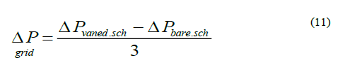

According to the equation 11, the pressure drop caused by the spacer grid and the swirl-type mixing vanes is the same for each grid in a given Reynolds number and the maximum value is 7.85 kpa for each spacer grid for Reynolds number 610000, which is proportional to the inlet velocity of 6 m/s. The minimum value of the local pressure drop is also 3.53 kpa for each grid for Reynolds number 410000, which is proportional to the inlet velocity of 4 m/s. The average value of relative local pressure drop for each spacer grid in the core of the reactor is also 21.8% concerning the equation 12 in the Reynolds number range used in the simulations. To further investigate the calculated pressure drop, the values obtained from the numerical solution are compared with the experimental values presented by Blasius correlation for the frictional pressure drop, and Rehme and Trippe correlation for the local pressure drop and illustrated in Figure 17 [17,18]. According to these correlations and considering the existence of three spacer grids in the computational domain, the amount of pressure drop in the core of the reactor is calculated by using equation 13. Since coolant flows in a closed loop practically, gravity pressure drop is excluded from calculations.


Figure 16: Pressure distribution along the axis for vaned subchannel.
In equation 13, the first right term is the frictional pressure drop equation and the second right term is the local pressure drop equation due to the blockage of the spacer grid with swirl-type mixing vanes. As shown in Figure 17, the numerical simulation results are in good agreement with the experimental results obtained from the empirical correlations and the maximum difference between the correlation and numerical solutions is 5%.

Figure 17: Comparison of numerical results and experimental correlations for total pressure drop of reactor core
Conclusion
The results of single-phase analysis of small modular pressurized water reactor core by the numerical method using CFD in different Reynolds numbers showed that using swirl-type mixing vanes improves heat transfer, although these vanes increase reactor core pressure drop. This is due to the local increase in turbulence in grids areas.
• Secondary flow intensity increases by 43% in grid area and is the same for different Reynolds numbers.
• Local increase in turbulence and fluid displacement causes the average temperature of the fuel rods surface to decrease by 1.75°C.
• Heat transfer coefficient increases locally by the maximum of 27.6%.
• Using swirl-type mixing vanes can increase the reactor output power by 19.8% with causing a reasonable pressure drop in the reactor core.
• Although spacer grids with swirl-type mixing vanes improve the heat transfer of the reactor core, their application increases the core pressure drop and each vaned grid increases the pressure drop by 21.8%.
Large computational domain and high computational cost of Direct Numerical Simulation (DNS) method were limitations of the present study. To overcome the limitations of the study, sub-channel approach and k-ε turbulence model are used. Future studies can focus on considering sub-cooled flow boiling in the core, enhancing thermohydraulic performance of different mixing vanes and increasing safety margins of SMRs.
References
- Kim KK, Lee W, Choi S, Kim HR, Ha J (2014) SMART: The first licensed advanced integral reactor. J Energy Power Eng 8: 94.
- Vujic J, Bergmann RM, Skoda R, Miletic M (2012) Small modular reactors: Simpler, safer, cheaper?. Energy 45: 288-295.
- Liu Z, Fan J (2014) Technology readiness assessment of Small Modular Reactor (SMR) designs. Prog Nucl Energy 70: 20-28.
- Karouta Z, Gu CY, Scholin B (1995) 3-D flow analyses for design of nuclear fuel spacer.
- Todreas NE, Kazimi MS (1990) Nuclear systems II: Elements of thermal hydraulic design. Taylor and Francis, England. [Crossref] [Google Scholar] [PubMed]
- In WK, Oh DS, Chun TH (2001) Flow analysis for optimum design of mixing vane in a PWR fuel assembly. Nucl Eng Technol 33: 327-338.
- Seo H, Park SD, Seo SB, Heo H, Bang IC (2015) Swirling performance of flow-driven rotating mixing vane toward critical heat flux enhancement. Int J Heat Mass Transf 89: 1216-1229.
- Sohag FA, Mohanta L, Cheung FB (2017) CFD analyses of mixed and forced convection in a heated vertical rod bundle. Appl Therm Eng 117: 85-93.
- Nematollahi M, Nazifi M (2008) Enhancement of heat transfer in a typical pressurized water reactor by different mixing vanes on spacer grids. Energy Convers Manag 49: 1981-1988.
- Liu C, Ferng Y, Shih C (2012) CFD evaluation of turbulence models for flow simulation of the fuel rod bundle with a spacer assembly. Appl Therm Eng 40: 389-396.
- Podila K, Rao Y, Krause M, Bailey J (2014) A CFD simulation of 5 × 5 rod bundles with split-type spacers. Prog Nucl Energy 70: 167-175.
- Cinosi N, Walker S, Bluck M, Issa R (2014) CFD simulation of turbulent flow in a rod bundle with spacer grids (MATIS-H) using STAR-CCM+. Nucl Eng Des 279: 37-49.
- Launder BE, Spalding DB (1983) The numerical computation of turbulent flows. In Numerical prediction of flow, heat transfer, turbulence and combustion. Elsevier, Netherlands, 96-116.
- Weisman J (1959) Heat transfer to water flowing parallel to tube bundles. Nucl Sci Eng 6: 78-79.
- In WK, Shin CH, Lee CY (2015) Convective heat transfer experiment of rod bundle flow with twist-vane spacer grid. Nucl Eng Des 295: 173-181.
- Lee C, Choi Y (2007) Comparison of thermo-hydraulic performances of Large Scale Vortex Flow (LSVF) and Small Scale Vortex Flow (SSVF) mixing vanes in 17× 17 nuclear rod bundle. Nucl Eng Des 237: 2322-2331.
- Maskal AB, Aydogan F (2017) Mathematical spacer grid models for single phase flow. Ann Nucl Energy 103: 130-146.
- Rehme K, Trippe G (1980) Pressure drop and velocity distribution in rod bundles with spacer grids. Nucl Eng Des 62: 349-359.