Spanish
  Chinese
  Russian
  German
  French
  Japanese
  Portuguese
  Hindi
Hindi Research Article, J Nucl Ene Sci Power Generat Technol Vol: 11 Issue: 5
Power Quality Improvement on 11 kV/440 V Distribution System Using DSTATCOM
SR Reddy1*, PV Prasad2 and GN Srinivas3
1Department of EEE, Guru Nanak Institutions Technical Campus, Hyderabad, India
2Department of EEE, Chaitanya Bharathi Institute of Technology, Gandipet, Hyderabad, India
3Department of EEE, Jawaharlal Nehru Technological University, Hyderabad, India
*Corresponding Author: SR Reddy
Department of EEE, Guru Nanak Institutions Technical Campus, Hyderabad, India
E-mail: sadurajender@gmail.com
Received date: 22 April, 2023, Manuscript No. JNPGT-23-96830;
Editor assigned date: 24 April, 2023, PreQC No. JNPGT-23-96830 (PQ);
Reviewed date: 08 May, 2023, QC No. JNPGT-23-96830;
Revised date: 21 June, 2023, Manuscript No. JNPGT-23-96830 (R);
Published date: 29 June, 2023, DOI: 10.36648/2325-9809.100354
Citation: Reddy SR, Prasad PV, SrinivasGN (2023) Power Quality Improvement on 11 kV/440 V Distribution System Using DSTATCOM. J Nucl Ene Sci Power Generat Technol 12:5.
Abstract
At the PCC and source side current and voltage harmonics is compensated by utilizing, a distribution static compensator. In this work, we also compensated voltage control and reactive power correction. An improved reference current switching signal is suggested using a synchronous reference frame control technique. The analysis is done on 11 kV/440 V three phase four wire unbalanced nonlinear load distribution system. The DC link voltage and harmonic reduction, of the suggested distribution system performance is compared with the PI and fuzzy logic controllers. Harmonic distortion is reduced and reactive power is successfully compensated with the suggested method. This simulation results are obtaining by MATLAB/SIMULINK software.
Keywords: Harmonic distortion; Proportional Integral (PI) controller; Fuzzy logic controller; Hysteresis current controller; Distribution Static Compensator (DSTATCOM)
Introduction
Power electrical devices have become increasingly popular in the industrial sector over the past decade due to their ability to transmit power more efficiently [1]. Disturbances in power quality, like harmonic problems, unbalanced load flows, and reactive power issues, have come about because of the more utilization of power electronic equipment and nonlinear loads. This power quality effects motors and transformers overheat, sensitive devices fail, power factor decreases, effectiveness of system decreases etc. [2,3]. Another issue with power quality is a voltage unbalance in the supply due to unbalanced load. It decreases the torque of an electric machine drive system and causes negative sequence currents [4,5]. The unbalance and nonlinear load increases the risk of high neutral current and other power quality issues. Custom power devices like Distribution Static Compensators (DSTATCOM), Dynamic Voltage Restorers (DVR), and Unified Power Quality Conditioners (UPQC) are utilized to compensate these power quality issues. Distribution static compensators outperform compared to other custom power devices, when it comes to correcting reactive power, reducing harmonics, unbalancing loads, voltage fluctuations, and current harmonics in the distribution network [6]. Power quality issues and neutral current correction can be solved with topologies based on transformers and inverters [7]. DSTATCOM employs a transformer based methods that can include, among other configurations, a VSI with three legs and a zigzag transformer, T connection, or star delta topology [8]. The zero sequence part of the current is eliminated through utilizing a transformer, and positive and negative currents are compensated for utilizing three leg VSIs [9]. The inverter based DSTATCOM incorporates a three leg VSI with a split stage capacitor, a four leg VSI, and a three leg VSIs with split phase capacitor. There are merits and demerits associated with each of these approaches [10]. In This design utilises a three legged VSI with a split phase capacitor. To regulate the correct DC-interface voltage, a Proportional Integral (PI) controller is an integral part of the SRF control method. Inaccurate outcomes may be produced by the PI controller if it is exposed to changes in input parameters, load, etc., and the controller needs precise mathematical model values, which can be difficult to acquire [11-13]. The use of a fuzzy logic processor in DSTATCOM is currently the subject of considerable interest. Fuzzy logic controllers are preferable to PI controllers because they are more forgiving of imperfect input values and do not necessitate precise values for the mathematical models they are based on. For SRF controlled DSTATCOM, the Mamdani form of fuzzy logic processor is most commonly used because it produces the best outcomes. The fuzzy logic controller providing better compensation as compared to the Proportional Integral (PI) controller in DSTATCOM [14-16].
For 11 kV/400 V distribution system, an SRF controlled DSTATCOM with split-phase capacitor VSI is proposed and developed in this work. Unbalanced nonlinear load circumstances are simulated and the suggested DSTATCOM's harmonic reduction and DC link voltage control capabilities are evaluated.
Materials and Methods
Configuration of the system
Distribution Static Compensator (DSTATCOM) system arrangement for a three phase, four-wire distribution system with an unbalanced nonlinear load is shown in Figure 1. Before being connected to the unbalanced nonlinear load, the 11 kv three phase source voltage is brought down to 400 V through the use of 11/0.4 kV three phase transformer. Harmonics are introduced at the PCC by the connected unbalanced nonlinear load.

Figure 1: System configuration.
A split phase capacitor connected to DSTATCOM at the PCC can reduce harmonics and prevent unbalance loading at the PCC and the load. It is possible to enhance load balancing, power factor correction, and line voltage regulation by connecting at the bus.
The DSTATCOM consist of, a dc-link voltage regulator, three leg voltage source inverter, interface inductor (Lf), and a split phase capacitor. Connecting three phase ripple filters of resistance (rf) and capacitor (cf), switching and voltage transients caused by DSTATCOM are eliminated. The SRF and hysteresis band current control are used to generate the modified control switching signals that are sent to switching of the VSI based DSTATCOM.
Proposed control algorithm
The proposed SRF control algorithm block diagram is shown in Figure 2. The control method is used to obtain the fundamental switching reference control signals for switching of VSI-based DSTATCOM, for harmonic and reactive power correction under unbalanced nonlinear load situation.

Figure 2: Block diagram of the suggested control method.
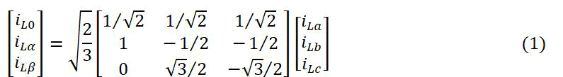
In a three phase system, the nonlinear load currents divided into active current, the reactive current, and the harmonic current. For compensation reasons, in this method separates the reactive current and harmonic current. Separation is achieved by applying Clark's transformation equation (1). To covert the three-phase load currents into a two phase fixed α-β-0 line.
Using the below park transformation condition, the present α-β-0 current axis components are changed to d-q-0 (d-direct axis, q-quadrature axis parts).
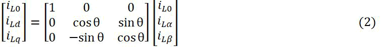
The transformation angle denoted by the symbol θ here. The cos θ and sin θ are derived from the voltage source's three phase PLL block (phase locked loop) when voltage and current are synchronized.
The terms iLd and iLq, which stand for instantaneous active and reactive load current, after their reactive components of current have been isolated. As shown in equation (3) and (4), both the average (dc) and fluctuating (isolating) values of the current's two components can be calculated.
iLd=iddc+idac (3)
iLq=iqdc+iqac (4)
The iddc is average or dc part of iLd, while idac and fluctuating or ac part of iLq. For this situation, the fluctuating parts are to be appeared like ripple. Active and reactive current parts are given as equation (5) and (6), separately, after the fluctuating current part has been eliminated by utilizing a low pass filter.
iLd=iddc (5)
iLq=iqdc (6)
The iLoss current component is added to the average active reference current part iddc of the d-axis in a d-q frame. The iLoss current component is obtained from the PI or fuzzy logic controllers, which is used to maintain to keep a constant DC bus voltage and supply losses in DSTATCOM. For this reason, the active reference current is given in equation (7)
iLd*=iddc+iLoss (7)
For harmonic and power factor adjustment, the direct axis reference current (iLd*) is employed.
Likewise, the reactive current (iqr) should be provided by the source to keep a steady voltage at the PCC. In the same manner as the direct current axis component, this current is added to the average reference part (component) of current (iqdc) of the q-axis in the d-q frame. The ensuing portion of the reactive reference current is
iLq*=iqdc+iqr (8)
The PI controller's (regulator's) output is the reactive current (iqr), and the PI regulator's input is the value of the voltage Vs, which can be subtracted from the reference voltage Vs*. An illustration of the PCC voltage magnitude is provided below:

Output of the PI controller is:
Vqr(n)=Vqr(n-1)+Kpq(Vte(n)-Vte(n-1))+KiqVte(n) (10)
The Vte(n)=V*s (reference voltage amplitude)–Vs.(n)(actual terminal voltage amplitude) at nth time sampling. Kpq (proportional) and Kiq (Integral) gain of the PI controller.
The part of the reference current known as the reactive current (iLq*) is used to rectify reactive power and regulate ac voltage.
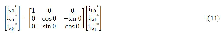
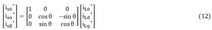
Active and reactive reference current parts (iLd*, iLq*) can be changed over completely to the α-β-0 frame by utilizing inverse Park's condition (transformation) equation (11).
Inverse Clark's equation is used to transform the reference current to three phase currents (a, b, c) by equation (12).
The hysteresis band controller analyzes the got three phase reference currents (isa*, isb*, and isc*) to the actual compensating filter currents in order to improve VSI switching with IGBTs. This hysteresis band controller's main advantages are its simplicity, increased stability, and quick response time. The primary disadvantage of the carrier based controller in comparison to the hysteresis band controller is the strain that its varying switching frequency places on the switching devices [17].
Dc voltage regulation
The accuracy with which the adjusting reference current is generated, which is a process heavily influenced by the voltage control of the dc bus is essential to the performance and accuracy of DSTATCOM. To meet the demands of the compensating current, the voltage across the dc bus (Vdc) either increases or decreases. The dc side of the inverter needs to remain steady at a predetermined reference value in order to work VSI properly. VSI is able to compensate for the power losses caused by its filters and switches by maintaining a stable dc-link voltage. In rotating frame theory, the d-axis average active current component (iddc) must be added by a controller to manage or maintain a constant dc-link voltage. This section includes a comparison of two controller devices.
• PI controller.
• Fuzzy logic controller.
PI controller: Figure 3 shows the PI controller block structure. It is shows the how the internal framework functions inside, While compensating losses of DSTATCOM and filters, the source should likewise to give the active reference current part (iLd) and the losses reference current part (iLoss). At the nth sampling moment, VSI obtained current loss reference component (iLoss) is found by comparing the reference dc bus voltage Vdc* to the actual dc bus voltage Vdc (Vdc1+Vdc2=Vdc) (iLoss).
Vde(n)=Vdc*(n)-Vdc(n) (13)
The loss component (iLoss) at the nth testing moment can be computed using the contrasted error signal Vde(n), which is specified as
iLoss(n)=iloss(n-1)+kpd (Vde(n)-Vde(n-1))+kid Vde(n) (14)
The kpd=0.6, and kid=0.09 are proportional and integral values of the PI controller. For the DSTATCOM, the PI controller created for the loss reference part (iLoss). While managing the active reference current (iLd*), it is important to add the loss reference current part (iLoss) to the average active reference current (iLd). A hysteresis band controller is needed for improved VSI switching with IGBTs. In this paper, the compensated reference current component and the actual compensating filter currents are compared.

Figure 3: Diagram of the PI controller block.
Fuzzy logic controller: The proposed internal circuit of the fuzzy logic controller as shown in Figure 4a. It is comparing the reference voltage of the dc bus capacitance to actual dc bus voltage and generate error signal. A fuzzy logic controller processes that error signal (Figure 4b).
Fuzzy logic controller output is combined with fundamental active current to provide active power for dc-bus voltage regulation and VSI losses compensation. An error signal is generated when the calculated compensating current is compared to the measured compensating current in the filter hysteresis region (Figure 4c). The error signal runs the VSI (Figure 4d).
The Fuzzy Inference System (FIS) is made up of the defuzzification module, the rule proof reader, the rule viewer, the surface viewer, and the membership function editor [18].

Figure 4a: Controller block diagram of fuzzy logic.
This work presents the fuzzy interface system, we developed as
• The input-output analysis (2 inputs and 1 output).
• Membership functions (seven).
• Type of implication (Mamdani max-min operation).
• Defuzzification method (centroid of area method).
• Rule count: (49 rules).
• Function of input membership (Gaussian).
• What's the input membership function (triangular).
This decision each input and output pair has N linguistic variables, for a total of N2. These N2 pairs can yield any one of M potential values for the decision variables. States encompass every conceivable permutation. The total number of fuzzy matrix is (N2*M)=49. Membership duties are controlled by these 49 states (Table 1).
Fuzzy logic controller has greater reaction and enhances DSTATCOM behaviour than the other controller.

Figure 4b: The function of gaussian memberships for the input variable E.

Figure 4c: It can be shown that change in input variable (ΔE) membership function.

Figure 4d: The function of a triangular output variable's membership.
| E/ΔAE | NB | NM | NS | ZE | PS | PM | PB |
|---|---|---|---|---|---|---|---|
| NB | NB | NB | NB | NB | NM | NS | ZE |
| NM | NB | NB | NB | NM | NS | ZE | PS |
| NS | NB | NB | NM | NS | ZE | PS | PM |
| ZE | NB | NM | NS | ZE | PS | PM | PB |
| PS | NM | NS | ZE | PS | PM | PB | PB |
| PM | NS | ZE | PS | PM | PB | PB | PB |
| PB | ZE | PS | PM | PB | PB | PB | PB |
Table 1: A summary of decision rules.
Results and Discussion
The MATLAB/SIMULINK implementation of the suggested DSTATCOM model is controlled by the PI and fuzzy logic controllers with synchronous reference frame control method. An unbalanced nonlinear load is used to test the model's accuracy. The suggested model is utilized for voltage control, power factor adjustment, and harmonic mitigation at the PCC. Also analysis is done by comparison of PI and fuzzy logic controller. The simulation time was observed between 0.2 and 0.3 seconds in order to obtain a clearer picture. The following cases are used to evaluate the effectiveness of DSTATCOM:
• Unbalanced nonlinear load without DSTATCOM.
• PI controlled DSTATCOM.
• Fuzzy logic controlled DSTATCOM.
• THD analysis.
Unbalanced nonlinear load without DSTATCOM
The unbalanced nonlinear load introduces harmonics in the source current waveform (bus-1) as shown Figure 5a and b. At the PCC, the voltage and current waveforms are distorted due to harmonics introduced by the unbalanced nonlinear load (bus-2) is observed from Figure 5c and Figure 5d. The load voltage and load current are observed in Figure 5e and Figure 5f. Figure 5g. PCC (bus-2) current waveform of phase-A, unbalanced nonlinear load without DSTATCOM.

Figure 5: a) Waveform of the source voltage; b) Waveform of the source current; c) The PCC (bus-2) voltage waveform; d) PCC (bus-2) current waveform; e) Load voltage waveform; f) Waveform of the load current; g) Per phase of the PCC current waveform, unbalanced nonlinear load without DSTATCOM.
DSTATCOM with PI controller
When a DSTATCOM controlled by SRF controlled algorithm is connected at the PCC, it supplies the reactive power expected to compensate for source current harmonics and voltage and current harmonics at the PCC. The DC-interface voltage is regulated by a PI controller. Figure 6a and b and Figure 6c show the compensated source and PCC harmonics waveforms. The controlled and adjusted voltage at the PCC is shown in Figure 6d. As can be seen in Figure 6e. The load voltage is also regulated. The waveform of the load current is shown in Figure 6f, Figure 6g depicts the DC-link voltage wave form, Figure 6h. Shows the load current waveform represented per phase, and Figure 6i. Depicts the PCC current wave form. Figure 6j. Depicts a waveform of voltage and current.

Figure 6: a) Voltage waveform at the source; b) Waveform of the source current; c) compensated of voltage at the PCC (bus-2); d) Current waveform at the PCC (bus-2); e) Waveform of the load voltage; f) Waveform of load current; g) DC bus voltage; h) The load current waveform is shown individually phase-A; i) waveform of the current at the PCC of phase-A; j) The voltage and current waveforms at the PCC (bus-2), With PI controlled DSTATCOM.
DSTATCOM with fuzzy logic controller
When the DSTATCOM operated by the SRF controlled is connected at the PCC, it compensate for voltage and current harmonics caused by the unbalanced nonlinear load. The DC bus voltage is controlled by fuzzy logic controller. Figure 7 shows the harmonic and reactive power compensation by fuzzy logic controlled DSTATCOM. The fuzzy logic controller advantage providing better compensation as compared to the PI controller. R-C filter are connected at the PCC. The rectified PCC and source current waveforms is shown in Figure 7a and b, Figure 7d and Figure 7c. Shows the compensated PCC voltage waveform, Figure 7e. The voltage at the load is also compensated, Figure 7f. Shows the load current waveform, Figure 7g. For the DC-link voltage wave form, Figure 7h. For the load currents per-phase representation, and Figure 7i. For the PCC current wave form. Figure 7j. Waveforms of voltage and current.

Figure 7: a) Source voltage waveform; b) The source current waveform; c) The voltage waveform at the PCC (bus-2); d) Current waveform at the PCC (bus-2); e) the waveform of the load voltage; f) The waveform of load current; g) DC bus voltage; h) The load current wave shape is shown individually for each phase; i) The waveform of the current at the PCC-A. (j) PCC (bus-2) voltage and current waveform, with fuzzy logic controlled DSTATCOM.
Total Harmonic Distortion analysis (THD)
At the source and PCC, we investigate how DSTATCOM affects the suggested system's overall harmonic distortion. This THD Analysis of proposed system is done with PI and a fuzzy logic controllers
Unbalanced nonlinear load without DSTATCOM
Figure 8 shows the overall harmonic distortion introduced into the system when a nonlinear load is connected but without DSTATCOM. Harmonic distortion at the PCC current is 27.50% and at the PCC Voltage is 12.92% shown in Figure 8a and Figure 8b. Figure 8c, the harmonic distortion in source current is 16.32%.

Figure 8: a) The current THD at PCC; b) THD (voltage) at the Point of Common Coupling (PCC); c) THD of source current waveform (bus-1).
DSTATCOM with PI controller
DSTATCOM, when connected into the suggested system, decreases the current and voltage harmonics at the PCC to 2.43% and 3.49%, respectively shown in Figure 9a and Figure 9b. As ought to be noticeable in Figure 9c. The harmonic distortion of the source current has been decreased to 2.02%.

Figure 9: a) PCC current THD; b) THD (voltage) at the Point of Common Coupling (PCC); c) THD of source current (bus-1).
With a fuzzy logic controller, DSTATCOM
DSTATCOM, controlled by fuzzy logic, lowers current harmonic distortion at the PCC from 27.50 % to 1.56 %, and it lowers voltage harmonic distortion at the PCC from 12.92 % to 2.84 % as shown in Figure 10a and Figure 10b. Figure 10c. Clearly shows that the amount of harmonic distortion in the source current also reduced to 1.55 %.

Figure 10: a) Current THD at PCC; b) THD (voltage) at the Point of Common Coupling (PCC); c) THD at the source current (bus-1).
The above total harmonic distortion analysis shows that the fuzzy logic controller DSTATCOM is more effective at reducing harmonic distortion than the PI controller DSTATCOM.
Conclusion
This work investigates the effectiveness of VSI based DSTATCOM in balancing reactive power, lowering harmonics, and controlling voltage in a three phase, three wire, unbalanced nonlinear load distribution system by utilizing the synchronous reference frame control technique. The proposed control method easy to understand and effectively compensate for unbalanced nonlinear load distribution system. The proposed system simulation results are analysed and compared with the PI and Fuzzy logic controller. By combining their efforts, both processors are able to keep the dc bus voltage stable regardless of the external disturbances. While both controllers are effective at compensating for unbalanced nonlinear loads, but the fuzzy logic controller provides better compensation in unbalanced nonlinear load distribution system. MATLAB/SIMULINK is used to run the simulations and for obtain the results. The results show that compared to a PI-controlled DSTATCOM, with fuzzy logic control offers a more dynamic reaction from the system, which in turn leads to improved transient behaviour and power quality.
References
- Bose B (2013) Global energy scenario and impact of power electronics in 21st century. IEEE Trans Ind Electron 60:2638-2651.
- Hive S, Chatterjee K, Fernandes BG (2004) VAr compensation and elimination harmonics in three-phase four wire system based on unified constant frequency integration control. 11th Int Conf Harm Quality, Power 647-651.
- George M, Basu KP (2008) Modelling and control of three phase shunt active power filter. Am J Appl Sci 5:909-916.
- Myoung Lee G, Lee D, Seok J (2004) Control of series active power filters compensating for source voltage unbalance and current harmonics. IEEE Trans Ind Elect 51:132-139.
- Singh B, Chandra A, Al-Haddad K (1998) Reactive power compensation and load balancing in electric power distribution systems. Int J Electr Power Energy Syst 20:375-381.
- Arya SR, Singh B, Niwas R, Chandra A, Al-Haddad K(2016) Power quality enhancement using DSTATCOM in distributed power generation system. IEEE Trans Ind Appl 52:5203-52122.
- Singh B, Jayaprakash P, Somayajulu TR, Kothari DP (2009) Reduced rating VSC with a zig zag transformer for current compensation in a three phase four wire distribution system. IEEE Trans Power Del 24:249-259.
- Singh B, Jayaprakash P, Kothari DP (2008) A T connected transformer and three leg VSC based DSTATCOM for power quality improvement. IEEE Trans Power Elect 23:2710-2718.
- Singh B, Arya SR, Jain C, Goel S (2014) Implementation of four leg distribution static compensator. IET Gener Transm Distrib 8:1127-39.
- Mishra MK, Ghosh A, Joshi A, Suryawanshi HM (2006) A novel method of load compensation under unbalanced and distorted voltages. IEEE Trans Power Deliv 22:288-295.
- Singh B, Jayaprakash P, Kothari DP, Chandra A, Al Haddad K (2014) Comprehensive study of DSTATCOM configurations. IEEE Trans Industr Inform 10:854-870.
- Suresh M, Panda AK (2011) PI and fuzzy logic controller based 3-phase 4-wire shunt active filter for mitigation of current harmonics with id-iq control strategy. J Power Elect 11:914–921.
- Aredes M, Hafner J, Heuman K (1997) Three phase four wire shunt active filter control strategies. IEEE Trans Power Elect 12:311-318.
- Suresh M, Panda AK (2012) Real time implementation of PI and fuzzy logic controllers based shunt active filter control strategies for power quality improvement. Int J Elect Power Energy Systems 43:1114-1126.
- Mamdani EH (1997) Application of fuzzy logic to appropriate reasoning using linguistic synthesis. IEEE Trans Comp 26:1182-1191.
- Chaoui A, Gaubert JP, Krim F, Champenois G (2007) PI controlled three phase shunt active power filter for power quality improvement. Electr Power Comp Systems 35:1331-1344.
- Runkler TA (1997) Selection of appropriate defuzzification methods using application specific properties. IEEE Trans Fuzzy Sys 5:72-79.
- Jang JS, Sun CT, Mizutani E (1997) Neuro fuzzy and soft computing-a computational approach to learning and machine intelligence. IEEE Trans Automatic Cont 42:1482-1484.