Spanish
  Chinese
  Russian
  German
  French
  Japanese
  Portuguese
  Hindi
Hindi Research Article, J Nucl Ene Sci Power Generat Technol Vol: 11 Issue: 6
Simulation of Heat Transfer in Solar Air Heaters with a Concave Blower Absorber
BA Abdukarimov* and AA Kuchkarov
Department of Construction of Engineering Communications, Fergana Polytechnic Institute, Fergana, Uzbekistan
*Corresponding Author: BA Abdukarimov
Department of Construction of
Engineering Communications,
Fergana Polytechnic Institute,
Fergana,
Uzbekistan;
E-mail: bekzodek45484@mail.ru
Received date: 15 April, 2022, Manuscript No. JNPGT-22-60893; Editor assigned date: 18 April, 2022, PreQC No. JNPGT-22-60893 (PQ); Reviewed date: 02 May, 2022, QC No. JNPGT-22-60893; Revised date: 14 June, 2022, Manuscript No. JNPGT-22-60893 (R); Published date: 21 June, 2022, DOI: 10.4172/2325-9809.1000295
Citation: Abdukarimov BA, Kuchkarov AA(2022) Simulation of Heat Transfer in Solar Air Heaters with a Concave Blower Absorber. J Nucl Ene Sci Power Generat Technol 11:6.
Abstract
This article provides a general description of a new type of energy efficient tubular solar air heater operating on the basis of solar energy, including from renewable energy sources, which is considered relevant today. Also, in the working chamber of the solar air heater, the optimal variant of concave air ducts was used, which has the property of accelerating the heat exchange process, a mathematical model was created and solved using numerical methods. As a result of the study, the longitudinal distribution of heat and the flow rate were studied.
The article is aimed at determining the operating parameters of the device, as well as solving the problems of finding the optimal speed when entering the pipe. In the working chamber of the device, an analysis of air movement and the appearance of a vortex inside concave pipes were carried out.
When developing a mathematical model of the longitudinal distribution of heat and velocity in each air pipe of this concave tubular solar air heater, the Reynolds-averaged Navier Stokes equations (English RANS (Reynolds–averaged Navier-Stokes)) were used. The Spalart Allmares turbulence model was used to close the RANS equation. To solve the Reynolds and Spalart Allmares differential equations for convective terms, the scheme against the flow of A A Samarisky was used, and for the diffusion term, the scheme of central separations was used. For the difference approximation of the initial equations, the control volume method was used, and the relationship between velocities and pressure was found using the SIMPLE (SemiImplicit Method for Pressure Linked Equations) procedure.
Keywords: Navier stokes equations; Heater; Air pipeline; Absorber; Temperature; Dynamic and kinematic viscosity; Solar radiation; Extrapolation; Spalart-Allmares turbulence model
Introduction
Today, many researchers and scientists are conducting scientific research on the introduction of advanced technologies and equipment that can efficiently and economically save energy and energy resources in the heat supply system.
It is known that natural resources used on an industrial scale are rapidly declining, so the use of renewable energy sources allows us to preserve natural resources and the ecological situation at the current level [1].
From renewable energy sources, in accordance with the climate of Uzbekistan, the sun is the most alternative, and a heat carrier has been prepared for its heat. For this purpose, the issue of creating a concentrated heat supply system based on solar collectors of an air conditioner and a solar water heater, which is carried out in various designs, is of particular relevance [2].
In the future, the use of renewable energy sources in the Republic of Uzbekistan is undoubtedly necessary to maintain energy, environmental and economic security, as well as for the sustainable development of the energy sector. For future generations, the development of renewable and alternative energy sources is a necessary condition for the conservation of natural resources and environmental protection [3-4].
An example of this is solar collectors for heating, including for generating thermal energy based on solar energy. It is advisable to use air heating collectors to obtain warm air. Samples of air heating collectors were also examined.
Buildings with an air heating system, for example, gyms, warehouses, workshops, buildings that consume a high level of outdoor air, and residential buildings of the population. Partly now, after the introduction of the standard for low energy consumption, the percentage of heat consumption when heating the air in the ventilation system has become more important than the total heat consumption. The system used in combination with regulated ventilation and air collectors can cover a significant part of the required heat. With the help of air-heated solar collectors, full heat supply in winter is certainly impossible, the reason for this is the unfavorable relationship between the amount of incident solar energy and the amount of heat needed for heating.
Buildings for drying agricultural and industrial products, as well as grain, seeds, medicinal and medicinal plants, wood and building materials. The drying potential of an air-heated solar collector is approximately 0.2 to 0.7 kg of water vapor per hour for a collector surface area of 1 m2.
It is worth noting that air heating collectors are less common than liquid controlled collectors, but they have significant advantages over liquid heated collectors, which include the following:
• Air heating collectors do not freeze in winter;
• Heat carriers in extreme heat in summer do not leak outside;
• Corrosion problems are very rare;
• Collectors for air heating are less demanding, much cheaper materials;
• There will be no heat loss in the heat exchanger in the clamps when the heater uses heated air directly;
• Fire safety.
Taking into account the above, a solar air heater with a concave air pipe was developed, and its technical parameters and operating principle were studied [5].
Materials and Methods
Below is an overview of a solar air heater with a concave air pipe, developed as a result of the conducted research Figure 1.

Figure 1: General view of a four-section solar air heater with concave air tube.
A model of a solar air heater with a concave air pipe has been developed. The static and dynamic state of the proposed solar air heater is as follows: the length of this model is l=1350 mm, width a=750 mm, height h=62 mm. The exhaust pipe for heated air of this solar air heater (1 is installed above the center by the width of the solar air heater and above the center by the height, the diameter of the exhaust pipe for heated air is d=32 mm, a transparent window is installed in the upper part of the device (2, the window and the foundation are attached using an insulating material Figure 2.

Figure 2: Schematic diagram of a concave ducted solar air heater.
1-Exhaust pipe for heated air, 2-Glass, 3-Metal surface (absorber, 4-Concave air pipeline, 5-Air intake channels, 6-Box.
The working chamber of this solar air heater is equipped with concave air tubes (4), which have a concave geometric shape. In the working chamber of the collector placed dark metal (1) the thickness of the absorber, h1=3 mm, and the surface of its surface installed submersible air pipe (4) staggered Figure 3.

Figure 3: Initial and boundary conditions.
Here Ū0- flow rate at the pipe inlet, Ṝ- radius of a straight pipe, ṝ - radius of the curved part of the pipe, T0-the temperature in the pipe wall.
The length of each air pipe is l=120 mm, height of chip h=2 mm, the width of the chip a=15 mm, the diameter of the pipe d=32 mm.
The air intakes of the solar air heater (5 are installed depending on the air outlet pipes, a separate air intake pipe is installed for each channel, the diameter of these air intakes is d = 15 mm. The housing of the solar air heater, consisting of porous plastic with low thermal conductivity (6, ensures that the heat in the collector's working chamber is not wasted [6-8].
As a result of research conducted to improve the thermal efficiency of solar air heaters, it became possible to study and create new heating surfaces in the working chamber of solar collectors, and thanks to this, thanks to a new design with low thermal resistance of the optimal option, air adaptation is achieved by moving and accelerating the heat exchange process. When compiling a mathematical model of these processes, the Reynolds-averaged Navier-Stokes equations were used [9-10]. A system of equations is used for the numerical study of the problem.
The Reynolds-averaged Navier-Stokes equations, the Spalart- Allmares equation and the temperature propagation in a cylindrical coordinate system have the following form.
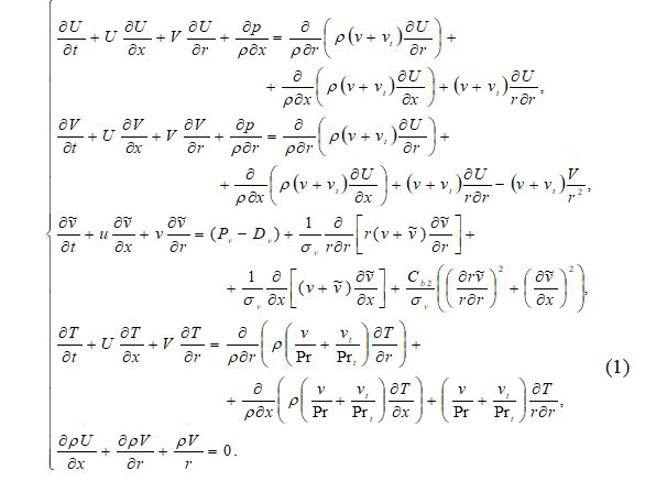
Here U,V– accordingly, the axial, radial and tangential components of the velocity vector of the air flow; P–hydrostatic pressure; ρ–gas density; ν-molecular viscosity; νt-turbulent viscosity of the air flow, - air temperature, Pr, Prt-turbulent and laminar Pr and tl numbers.
In order to solve the Reynolds and Spalart-Allmares differential equations, the following initial and boundary conditions were set.
Adhesion conditions are used in the walls, symmetry conditions are used in the axis, and extrapolation conditions are used in the output. These conditions were presented in Figure 3 [11-12].
The whole equation was presented in dimensionless form [13].
To calculate equation (1) of complex shapes, we change the coordinate system. Let's write the system (1) in the Mises variables (x,r) from (ξ,η). In the new variables, the derivatives are determined by the well-known formula:
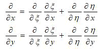
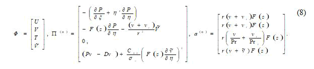
In the new variables, the system of equations (1) takes the form
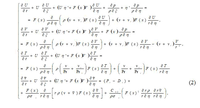
On systems equation (2) F(х)-a function that depends on the calculated area η’, η”- product coordinates, Pv-generation, Dvdissipation.
The numerical solution of the presented system of equations was carried out in the physical variables velocity-pressure by physically splitting the velocity and pressure fields simple [14]. The numerical solution of the transfer equation is carried out on a hybrid, staggered difference grid by the control volume method. According to this method, the solution of the Reynolds equations written in the cylindrical coordinate of the new variables includes two stages:
In the first stage, an intermediate grid function is defined for the velocity vector Ũ and Ṽ but these velocities do not satisfy the continuity equation. Therefore, a speed correction was made with a wave of pressure.
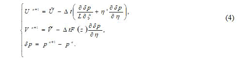
In the second stage, multiplying equation (4) by the gradient and taking into account the solenoids of the velocity vector on the (n+1)-m time layer, we obtain the Poisson equation to determine the pressure correction [15].
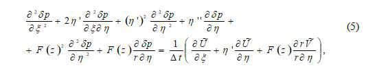
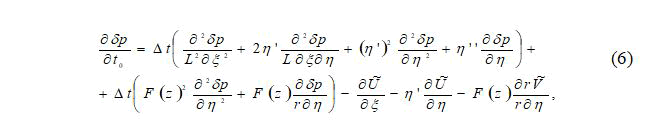
The solution of the stationary problem is carried out by the method of time determination, therefore the dependence (5) is written in the form of a non-stationary differential equation.
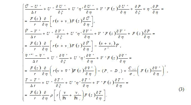
For the numerical solution of the transfer equation of the system (3), a finite-difference scheme against the flow of AA Samarsky was used, which has first-order accuracy, O (Δt, Δξ, Δη) [16].
The scheme against the flow has the form:
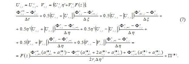
Here
Here π (Φ)- free members.
Results and Discussion
General analysis of the results obtained by the final method for special cases:
When analyzing the results obtained by the final method, changes in the aspiration of the duct at certain points at a certain time interval of the experiment in the direction of the central axis of the duct of a given temperature are graphically indicated [17].
Figure 4 below shows a general graph at different times t=10,20,30 of the temperature at a value of Re=698 in cross sections ξ=0.26,0.5,0.76.

Figure 4: Temperature propagation at Re=698.17 of different times and cross sections a) ξ=0.26, b) ξ=0.5, c) ξ=0.76.
From Figure 4 it will be possible to see that over time the heat on the surface moves to the central axis of the rib. In turn, an increase in the speed of the solar air heater in the air pipes leads to a slowdown in the longitudinal distribution of heat [18].
The results of the final method presented above, in the general analysis, were considered for the longitudinal distribution of heat in sunken air pipes of a solar air heater.
In order to ensure the reliability of the results obtained by numerical solution of the mathematical model, using the software package “COMSOL MULTIFYSICS 5.6”, which is currently one of the internationally recognized package programs, the longitudinal temperature distribution in the air ducts of the solar air heater was calculated. The obtained results were compared with each other and the adequacy of the mathematical model presented in the dissertation was proved. The average relative error was 4.6% (Figure 5).

Figure 5: Graphs of mutual comparison of the results of mathematical and simulation models.
1,2,3-results of the developed mathematical model, 4,5,6-results of the simulation model in the comsol multifysics software package.
Conclusion
A solar air heater with a concave air pipe and its static and dynamic state has been developed. The developed solar air heater investigated the movement of air in the working chamber. A mathematical model of the longitudinal distribution of heat and velocity in a concave air pipe of the device is developed. The nonlinear differential equations of Reynolds and Spalart-Almares were solved numerically, and the results were obtained.
References
- Abbasov YS, Uzbekov MO (2016) Studies efficiency solar air collector. Austrian J Tech Nat sci 7-8:13-17.
- Abdukarimov B, O'tbosarov S, Abdurazakov A (2021) Investigation of the use of new solar air heaters for drying agricultural products. In E3S Web of Conferences 264, 01031. EDP Sciences.
- Abbasov YS, Abdurazaqov AM (2021) Use of passive solar heaters in combination with local small boilers in building heating systems. Sci Tech J 3: 32-35.
- Abdurakhmanov AA, Kuchkarov AA, Mamatkosimov MA, Akhadov ZZ (2014) The optimization of the optical-geometric characteristics of mirror concentrating systems. Appl Sol Energy 50: 244–251.
- Kuchkarov AA, Kholov SR, Abdumuminov AA (2018) Optical Energy Characteristics of the Optimal Module of a Solar Composite Parabolic-Cylindrical Plant. Appl Sol Energy 54:293–296.
- Abdukarimov BA, Abbosov YS, O’tbosarov SR (2020) Hydrodynamic Analysis of Air Solar Collectors. Int J Adv Res Sci Eng Tech 7:13545-13549.
- Abdukarimov BA, Abbosov YS, Mullayev II (2019) Optimization of operating parameters of flat solar air heaters. Bull Sci Edu (19-2):6-9.
- Abobakirovich AB, Rustamjon O’g’li OS (2020) Relevance of use of solar energy and optimization of operating parameters of new solar heaters for effective use of solar energy. Int J Appl Res 6:16-20.
- Abbosov YS, Mominov OA, Xolikov AA (2020) Research of the hydraulic resistance coefficient of sunny air heaters with bent pipes during turbulent air flow. J Crit Rev 7:1671-1678.
- Wager BG, Nadezhina ED (1976) Using the Differential Dissipation Transfer Equation in Modeling the Surface Layer of the Atmosphere. Phys Atmos Ocean 12:345–355.
- Anuchin MG, Neuvazhaev VE, Parshukov IE (2001) Questions of atomic science and technology. Math Model Phys process 2:11-27.
- Anderson D, Tannehill J, Pletcher R (1990) Computational fluid mechanics and heat transfer. In 2 vols. Vol. 1: Trans. from English-Moscow: Mir, 384 .
- Malikov ZM, Madaliev ME (2021) Mathematical modeling of a turbulent flow in a centrifugal separator. Tomsk State Univ J Mat Mech.71:121–138.
- Kolmogorov AN (1968) Local structure of turbulence in an incompressible fluid at very high Reynolds numbers. Sov Phys Usp 10:734.
- Malikov ZM, Madaliev ME (2020) Numerical Simulation of Two-Phase Flow in a Centrifugal Separator. Fluid Dyn 55:1012–1028.
- Boussinesq J,de l’ T (1877) Presentes par Divers Savants. Acad Sci Inst Fr 23:46-50.
- Spalart PR (2009) RANS modelling into a second century. Int J Comput Fluid Dyn 23:291-293.
- Spalart PR, Shur ML (1997) On the sensitization of simple turbulence models to rotation and curvature. Aerosp Sci Technol 1:297-302.