Research Article, J Nucl Ene Sci Power Generat Technol Vol: 11 Issue: 1
Study on Behaviour of a Composite Space Truss Analytically
Prasanna Mishra1*, V. Vanathi2, T. Mohanapriya3
1Department of Automobile Engineering, PSG College of Technology, Coimbatore,TamilNadu, India
2Department of Civil Engineering, PSG College of Technology, Coimbatore, TamilNadu, India
3Department of Structural Engineering, PSG College of Technology, Coimbatore,TamilNadu, India
*Corresponding Author : Prasanna Mishra
Department of Automobile Engineering, PSG College of Technology, Coimbatore, Tamil Nadu, India
Tel: 9490303888;
E-mail: prasannamishra234@gmail.com
Received date: 29 December, 2021, Manuscript No. JNPGT-21-45668;
Editor assigned date: 31 December, 2021, PreQC No.JNPGT-21-45668(PQ);
Reviewed date: 14 January, 2022, QC No. JNPGT-21-45668;
Revised date: 21 January, 2022, Manuscript No. JNPGT-21-45668(R);
Published date: 24 January, 2022, DOI: 10.4172/2325-9809.1000250
Citation: Mishra P, Vanathi V, Mohanapriya T (2021) Study on Behaviour of a Composite Space Truss Analytically. J Nucl Ene Sci Power Generat Technol 11:1.
Abstract
A three Dimensional (3D) space truss structural member is used to transfer the force in 3D manner. The space truss is unstable and brittle in nature. Due to over loading, the buckling of one member may cause the subsequent failure in other members. This may even leads to collapse the entire structure. The slab will reduce the buckling in the chord member and to increase the stiffness. In this study a composite space truss model was created in Hyper Mesh-a FEM software using P ROD and P SHELL elements and its deflection values were obtained. Various design parameters such as grade of concrete, slab thickness, steel module sizes for truss members were incorporated in the software and the deflection values were found. Finally the optimum slab thickness for different grades of concrete and module size of steel truss by weight optimization and deflection criteria were found.
Keywords: FEM software; Slab thickness; Steel module sizes; Steel truss
Introduction
Trusses are triangular frame works in which the members are subjected to axial forces due to externally applied load. Steel members are generally more effective than members in flexure since the cross section is nearly uniformly stressed. Trusses are essentially axially loaded members and are very efficient in resisting external loads. They are extensively used for larger spans [1]. Steel trusses can be efficiently used along with concrete slabs in buildings and bridges by mobilizing composite action between structural steel and concrete there by improving their behaviour. To reduce deflection in space truss many attempts were taken like over strengthening of top chord members, use of different types of node connectors, use of concrete slab to act compositely with the top chord members and use of force limiting devices [2]. El-Sheikh, has studied the behaviour of composite space truss experimentally by strengthening the top chord member in a space truss. The composite action can introduce some ductility into the overall structural behaviour, but this approach may be successful in providing adequate warning of a sudden collapse. There was no serious damage to the composite space truss.
Sangeetha has studied the composite space truss with a slab thickness of 50mm using ABAQUS with a size of 4 m × 4 m (5 module) Deflection was reduced in the space truss compared with the previous experimental results. It was concluded that the deck slab without decking sheet at the top in space truss decreases the overall deflection of the structure. While comparing the experimental results with the analytical results the deflection decreases upto 17%. Ahmed El-Sheikh developed a new space truss system called Catrus. The main features of Catrus are its continuous chord members, simple jointing system and ability to work compositely with concrete slabs with the diagonals without node connectors. Experimental work involved five complete models. The results obtained indicated a significant ability to distribute forces away from affected areas and a good joint stability [3].
Materials and Methods
Introduction
The space truss of 6m × 6m with 3 different module arrangement as shown in figure1 where analysed. The module arrangements are Truss A with 7 module each of size 0.8571, Truss B with 6 module each of size 1m, and Truss C with 5 module each of size 1.2 m.
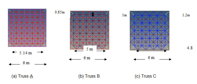
Figure 1:Modules with effective length.
Analytical work
The Composite truss was analysed using Finiteâ?Element Analysis using Hyper Mesh for three Trusses A, B and C. Truss element was modelled as one dimensional using PROD, the slab were modelled as two dimensional using shell element (PSHELL). All the inner nodes of the top chord members were subjected to an allowable roof live load of 1.5 kN/m2 and a superimposed dead load of 3 kN/m2. In case of bottom chord members the four corner nodes were simply supported [4]. Figure 2 shows the loading and boundary conditions.
Input values in hyper mesh
Parts created:
- Truss (P ROD)
- Slab (P SHELL)
Material properties:
Steel:
Density ρ =7850 kg/m3
Young’s Modulus E =200 GPa
Poisson ratio µ =0.288
Concrete:
Density ρ =2446.48 kg/m3
Young’s Modulus E =5000(fck)1/2
Poisson ratio µ =0.2
Young’s Modulus values for various grades of concrete:
E =25GPa (form25)
E =27.386GPa (forM30)
E =29.580 GPa (forM35)
Table 1: Details of truss members.
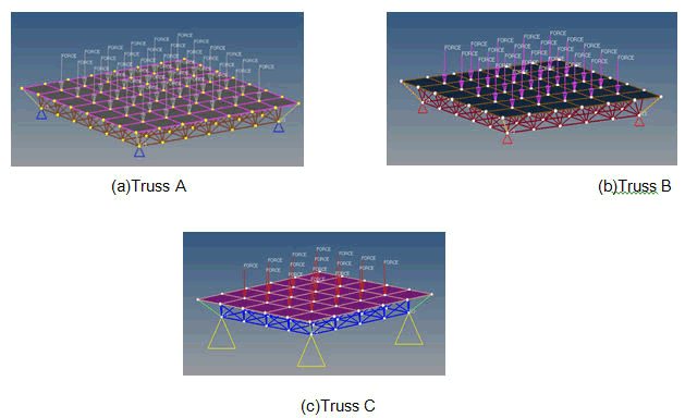
Figure 2:Different module arrangements of Truss A, B and C with loading and boundary conditions.
The Trusses A, B and C were analysed by varying
- Grade of concrete of the slab as m25, M30 and M35
- Slab thickness as 50 mm, 80 mm, 100 mm and 125 mm
- Module size as 0.8571 m, 1 m and 1.2 m
Interpretation of Results
Truss A-0.8571 m module size
The overall central deflection of the composite space trusses A, B and C were determined [5]. The values are tabulated in the Tables 2, 3, 4. The deflection profiles of the composite space trusses are shown in the Figures 4-6, 8-10, 12-14. Charts have been drawn showing the deflection reduction for slab thicknesses from 50 mm to 125 mm in Figures 3,7,11.
Table 2: Maximum central deflection for Truss A.
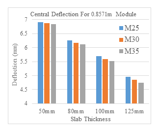
Figure 3:Graph showing slab thickness vs deflection for truss A
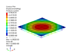
Figure 4:Deflection of truss A for 125 mm slab thickness and m25 grade.
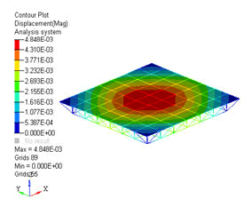
Figure 5:Deflection of truss A for 125 mm slab thickness and M30 grade.
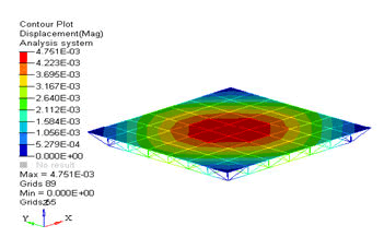
Figure 6:Deflection of truss A for 125 mm slab thickness and M35 grade.
Truss B-1 m module
The maximum central deflection of truss B with various grade of concrete and varying slab thickness is tabulated in Table 3.
Table 3: Maximum central deflection for truss B.
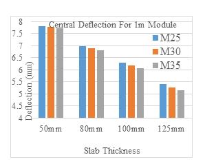
Figure 7:Graph showing slab thickness vs deflection for truss B.
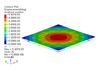
Figure 8:Deflection of truss B for 125 mm slab thickness and m25 grade.
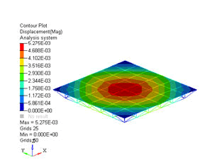
Figure 9:Deflection of truss B for 125 mm slab thickness and M30 grade.
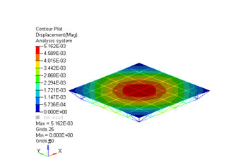
Figure 10:Deflection of truss B for 125 mm slab thickness and M35 grade.
Truss C-1.2 m module
The maximum central deflection of truss C with various grade of concrete and varying slab thickness is tabulated in Table 4.
Table 4: Maximum central deflection for truss C.
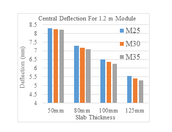
Figure 11:Graph showing slab thickness vs deflection for truss C.
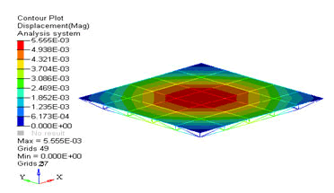
Figure 12:Deflection of truss C for 125 mm slab thickness and m25 grade.
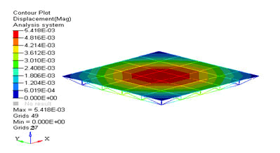
Figure 13:Deflection of truss C for 125 mm slab thickness and M30 grade.
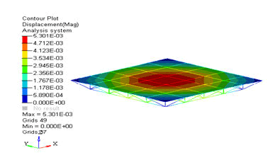
Figure 14:Deflection of truss C for 125 mm slab thickness and M35 grade.
Check for deflection
Effective span for truss A =5.1429 m
Permissible deflection =Eff. span/360
=5142.9/360
=14.285 mm
Maximum deflection obtained =6.905<14.285
Effective span for Truss B =5 m
Permissible deflecion = span/360
=5000/360
=13.888 mm
Maximum Deflection obtained =7.815<13.888
Effective span for Truss C =4.8 m
Permissible Deflection = span/360
=4800/360
=13.333 mm
Maximum Deflection obtained =8.300<13.333
Results and Discussions
Effect of module size
Three different module sizes were adopted for analysis.
- 0.8571 m
- 1 m
- 1.2 m
The percentage decrease in the central deflection of the composite space truss with the slab thickness 50 to 125 mm for various module sizes given in the Table 5.
Table 5: Percentage reduction in deflection for different module sizes.
Effect of concrete strength
Three different grades of concrete were adopted for analysis.
- m25
- M30
- M35
For the composite space Truss A the percentage decrease in the central deflection with respect to the concrete strength is 28.13% to 30.5% [6]. For Truss B the percentage of deflection reduction is 30.82% to 33.25%. And for Truss C it is 33.13% to 35.37%.
Effect of slab thickness
Four different slab thicknesses were adopted.
- 50 mm
- 80 mm
- 100 mm
- 125 mm
The percentage of decrease in central deflection for various slab thickness are given in the Table 6.
Table 6: Percentage reduction in deflection for change in slab thickness.
Optimum design parameters
- From the deflection results it is inferred that the composite truss having 0.8571 m module size has least deflection. From Table 7 it is observed that 1.2 m module size requires lesser quantity of steel (31.24%) and also satisfies the deflection criteria [7].
- From the results it is observed that M35 grade of Concrete shows less deflection compared to other concrete strengths.
- The deflection of composite truss having 125 mm thick slab is 35.37% lower than the truss having 50 mm thick slab [8].
From the observations it is inferred that the optimum design parameters for the composite space truss are
- 2 m Module size
- M35 Grade of concrete
- 125 mm slab thickness
Table 7: Weight of steel required for various module sizes.
Conclusion
Composite space truss was modelled using FEM Solver Hyper Mesh and analysed for the deflection values. The deflected profile are shown in the figures and the values are tabulated and the deflection check has been done. It is observed that the deflection decreases with increase in grade of concrete, increase in slab thickness and decrease in the module size. It is found that composite truss having 1.2 m module size with M35 grade of concrete and 125 mm slab thickness reduces the cost when weight of steel is considered. For composite truss having 0.8571 m module size with M35 grade of concrete and 125 mm thick slab performs well when deflection criteria is considered.
References
- El-Sheikh A (2000) New space truss system-from concept to implementation. Eng Struct 22: 1070-1085.
- El-Sheikh AI, El-Bakry H (1996) Experimental study of behavior of new space truss system. J Struct Eng 122: 845-853.
- El-Sheikh AI, McConnel RE (1993) Experimental study of behavior of composite space trusses. J Struct Eng 119: 747-766
- Murtha-Smith E (1994) Nonlinear analysis of space trusses. J Struct Eng 120: 2717-2736.
- Tedia A, Maru DS (2014) Cost, analysis and design of steel-concrete composite structure RCC structure. IOSR J Mech Civil Eng 11: 54-59.
- Sangeetha P, Senthil R (2017) A study on ultimate behaviour of composite space truss. KSCE J Civil Eng 21: 950-954.
- Sangeetha P (2020) Analytical study on the behaviour of composite space truss structures with openings in a concrete slab. Civil Environ Eng Report 30.
- Zhang D, Zhao Q, Li F, Tao J, Gao Y (2018) Torsional behavior of a hybrid FRP-aluminum space truss bridge: Experimental and numerical study. Eng Struct 157: 132-143.
 Spanish
  Chinese
  Russian
  German
  French
  Japanese
  Portuguese
  Hindi
Hindi 