Spanish
  Chinese
  Russian
  German
  French
  Japanese
  Portuguese
  Hindi
Hindi Research Article, Geoinfor Geostat An Overview Vol: 5 Issue: 3
Wireless Dependable IoT/M2M for Disaster Rescue and Healthcare – Reliable Machine Centric Sensing and Controlling
Masaki Noi1, Satoshi Seimiya1, Kouhei Harada1, Takumi Kobayashi2, Graeme K Woodward3 and Ryuji Kohno1,2*
1Graduate School of Engineering, Yokohama National university, Yokohama, Japan
2Centre for Future Medical Social Infrastructure Based on Information Communications Technology, Yokohama National University, Yokohama, Japan
3Wireless Research Centre, University of Canterbury, Christchurch, New Zealand
*Corresponding Author : Ryuji Kohno
Department of Electrical and Computer Engineering, Yokohama National University, Yokohama, Japan
Tel: + 045-339-3176
E-mail: kohnolabsecretary@ynu.ac.jp
Received: August 10, 2017 Accepted: September 14, 2017 Published: September 21, 2017
Citation: Noi M, Seimiya S, Harada K, Kobayashi T, Woodward KG, et al. (2017) Wireless Dependable IoT/M2M for Disaster Rescue and Healthcare – Reliable Machine Centric Sensing and Controlling. Geoinfor Geostat: An Overview 5:4. doi: 10.4172/2327-4581.1000167
Abstract
Wireless body area network (BAN) has been researched and developed for ubiquitous and remote medicine and its international standard IEEE802.15.6 was established in February, 2012. In order to find missing victims and sense their vital sign at disaster spots, highly reliable and secure, i.e. dependable BAN can be applicable to a body of robots, cars, UAVs (Unmanned Aerial Vehicle) like drones as well as a human body for dependable machine to machine (M2M) sensing and controlling. Such a M2M network can be called a ‘BAN of Things’ like Internet of Things (IoT). Around disaster areas unexpected obstacles and complicated radio propagation tend to prevent accurate ranging and positioning, and reliable vital data sensing. To perform precise localization and robust data communications by BAN, dependable radio technologies such as ultra wide band (UWB) radio, array antenna and error control codes in physical layer must be jointly optimized with MAC, Network, and application layers. Even after BAN has been developed and standardized globally, regulatory science must adopt it to guarantee the safety, reliability and security and to be compliant to regulations. This paper will introduce research and development, standard and regulatory compliance of dependable wireless BAN for disaster rescue and medical healthcare using UWB ranging and communication. The joint Japan and New Zealand project on remote sensing and controlling multiple UAVs to locate casualties in natural disasters such as earthquakes will be also introduced. The research has two objectives, one being to use UAVs to locate people under rubble, the other to collect information that is contained within the BANs those people are wearing. The new IEEE802.15 international standard group of dependable wireless networks IEEE802.15 IG-Dependability has been chaired by the author(Prof. Ryuji Kohno).
Keywords: Wireless body area network; BAN of things; UWB; Remote sensing and controlling multiple UAVs; Joint Japan and New Zealand project
Introduction
Earthquakes are well known as one of the natural disaster which should be most feared all over the world. Especially, some countries around the Pacific Ring of Fire such as Japan and New Zealand took on a lot of damage from the earthquakes frequently for example around Christchurch earthquakes in New Zealand and around Tohoku earthquake in Japan, February and March 2011, respectively. In Pan- Pacific region, natural disasters such earthquakes and Tsunami due to the earthquakes have been expected to happen more in a near future. As strategies against earthquakes, prediction of earthquakes, rescue of victims, and recovering infrastructures have been investigated. For us or researchers in a field of Information and Communication Technology (ICT), current popular Internet of Things (IoT) and Machine-to-Machine (M2M) based on advanced ICT can be applied for all the strategies. In particular, advanced wireless ICT must be such a core technology for rescue in disasters to perform accurate localization and monitoring detail health condition of victims. Under the disasters such like earthquakes, it is very important that looking for the victims and rescuing them can commence as soon as possible. However, such search and rescue is quite difficult because many roads and buildings may be broken down and debris is scattered on the ground making access difficult and hazardous, particularly with the likelihood of ongoing aftershocks.
This paper proposes a comprehensive system of searching and rescuing victims by using multiple Unmanned Aerial Vehicle (UAV) s such as drones with sophisticated wireless ICT such as Ultra Wide Band (UWB) radio technology which can perform accurate ranging for searching victims and reliable data transmission for sensing vital signs of victims (Figure 1). The flow of the proposed system is described at Figure 2. It mainly consists of four steps, in which the first step is precise localization using global navigation satellite system (GNSS) such as GPS and GLONASS [1,2] and UWB mutual ranging of UAVs and its recursive process, the second is rough to fine ranging process of a victim with particle filter, the third is a process of sensing vital signs such as ECG, pulses, temperature of victims and taking movies using medical wireless Body Area Network (BAN)s [3] and the fourth is wireless power feeding or transmission for recharging UAVs to keep flying for a longer time. UAV can discover victims in the damaged area without using roads and UWB localization system can estimate the position of victims even inside of the broken buildings even though GNSS cannot be available indoor. A rescue team can determine both the health condition and position of the victims by vital sign data and estimated position data that are transmitted by the BAN. This system can pursue a triage so as to rescue victims in the order of serious health condition. The proposed QoS-HARQ (Quality of Service based Hybrid Auto Repeat request) and wireless power feeding scheme can make UAVs flying time longer which is a key issue for all UAV practical operation.

Figure 1: Over view of the Japan and New Zealand Joint Project.

Figure 2: Flowchart of the Search and Rescue Scheme.
This paper is organized as follows. A proposed method of localization of victims by using UAVs and UWB localization system is proposed in Section 4. Physical layer technologies on wireless communication in order to achieve a dependable communication for UAV controlling and vital sign data transmission in wireless feedbackloop is presented in Section 5. Section 6 describes a proposal for achievement high efficiency wireless power feeding using microwave to make longer flight time of UAVs. Section 7concludes this paper.
Two-Step UWB Localization Method with Multiple Drones
System model
In this section, we are going to describe a method to estimate the position of the target that has BAN (Body Area Network) in three dimensions using three drones (Figure 3). Preconditions are as follows [4].

Figure 3: Expected Environment in the Disaster Rescue [4]
• Position of the drones themselves is determined by cooperative position estimation (Figure 4)

Figure 4: Cooperative Localization with Multiple Drones.
• The target is a fallen victim
• The arrangement of the drones is an equilateral triangle, all the same height from the floor
• The drone can recognize the height to the floor
Two Way Ranging Time of Arrival (TWR-TOA) is used to measure the distance between drones and between drones and targets. This method has features that do not require synchronization among terminals.
Particle filtering is used to infer the positioning from the raw distance measurements. However, when trying to increase the positioning accuracy, there is a disadvantage that the number of particles increases and the calculation complexity increases. Therefore, it is necessary to reduce the amount of calculations by scattering particles in an appropriate space and reducing unnecessary particles. We focused on the shape of the triangle consisting of two of the three drones and the target to find the appropriate space (Figure 5). Consider re-wording this, as the case when the victim is in the centre section of Figure 5 can still be an obtuse triangle, i.e. a2 > b2 +c2 can still be obtuse. In particular, we focused whether the shape of a triangle is an obtuse triangle or an acute triangle. Furthermore, in the case of an obtuse triangle, we focused on which side is the longest. In the case of Figure 5, whether it is an obtuse triangle or not can be confirmed from the cosine theorem by the following equation.

Figure 5: Geometrical Condition of Expected Environment in the Disaster Rescue [4]
b2 > a2 + c2 (1)
In other cases as well, roughly estimated areas can be calculated by comparing the square value of the longest side of the triangle and sum of the square values of the other two sides.
In the above explanation, only the case of two drones was explained, so the number of areas was three. However, if you use three drones, the triangle consisting of drone and target has the following three patterns.
• Drone1-Drone2-Tgt
• Drone2-Drone3-Tgt
• Drone3-Drone1-Tgt
Since these patterns can divide each area into three areas, using three drones can be divided into 19 areas (Figure 6) As shown in Figure 6, number 1 to 19 to each of the 19 divided areas, and this is called ‘AreaNum.’ The boundary line of each area is perpendicular to the line connecting the drones. For example, AreaNum=1 and AreaNum=2 will be described.

Figure 6: Geographical Distribution of Area Numbers [4].
AreaNum=1
There is no obtuse triangle in all three triangles composed of drones and targets. Alternatively, there are obtuse triangles with long sides AB, BC, CA.
AreaNum=2
‘AB-BT’ indicates that only the triangle A-B-Tgt is an obtuse triangle and the side B-Tgt is the longest side.
When the target is in AreaNum=1 to 7, positioning is performed with a particle filter in the corresponding space. In the case of other areas, the drone is moved to the approximate area based on the estimated AreaNum, and the area is judged again. This is because in the case of AreaNum=8 to 19, the range where the target exists cannot be narrowed. Perform the above procedure while positioning the drone closer to the target. In other words, it performs fine positioning from rough to sequential. Figure 7 is a flowchart showing these.

Figure 7: Legend
Simulation and consideration
In this section, we evaluate the positioning error and the calculation amount with respect to the number of times of movement. The proposed method is a hybrid of positioning using geometric conditions and positioning with particle filter. For this reason, the current comparison is based on positioning when each positioning method is used alone. The target randomly appears in the range of −30 [m] to +30 [m] on the x, y plane. We conducted a simulation to investigate its position.
Figure 8 shows how many times the drone moves and the change in the positioning error. From this figure, it can be seen that the proposed method can perform highly accurate positioning with fewer iterations compared to other methods. Also, you can see that it is performing fine positioning from rough. Figure 9 shows the number of multiplications used for positioning and the positioning error. From this figure, it can be seen that the proposed method is able to perform positioning with a smaller amount of calculation than when only the particle filter is used. In the case of using only the geometric condition, the calculation amount is the smallest. However, it is not possible to estimate the z coordinate only by geometric conditions as geometric conditions divides the area by only classifying whether it is an obtuse triangle or not. In Figure 6, you can see it is not possible to detect z-axis.

Figure 8: Number of Cooperative Positioning vs. Estimation Error in Locating the Target [4].

Figure 9: Calculation Amount vs Estimation Error in Locating the Target [4].
We showed that the range where the target exists can be specified by performing area judgment using geometric conditions. However, it is highly dependent on the arrangement of drones for area division. Therefore, if the arrangement of the drone is not horizontal with respect to the ground, the area division is also distorted. Also, calculating the area division was simple by setting the drone arrangement to an equilateral triangle. However, there is a disadvantage that calculation of area division becomes complicated as arrangement becomes complicated. However, if the anchor node can be moved like this time, the method has been shown to be effective.
PHY Technology for M2M Sensing and Controlling for Healthcare and Disaster Rescue
In this section, we are going to describe one of our proposed PHY technologies, QoS-HARQ, in which the controller changes the code rate for the control signals according to QoS (=how import the state of the controlled object is). In the wireless feedback control systems, reducing the packet loss is important. Using the code whose error correction capability is high may decrease such packet loss. On the other hand, redundancy in channel coding also decreases packet transmission rate although the bit rate remains the same. At the unstable controlled objects like UAVs without the automatic pilot mode / in the natural disaster, it may cause fatal mistakes. We are going to focus on how to reduce the unreliability of communication channels in control system by using the simplified model, the rotary inverted pendulum.
System model
We assume the wireless control system of a rotary inverted pendulum (Figure 10). There are four parameters describing the state of the controlled object (Tables 1 and 2) [5];

Figure 10: Wireless Feedback Control for a Rotary Inverted Pendulum [5].
| Mass of Pendulum M | 0.01 [kg] |
| Mass of Flinging-up Stick m | 0.02 [kg] |
| Length of a Flinging-up Stick l | 0.413 [m] |
| Length of the arm r | 0.235 [m] |
| Inertia of the Pendulum J | 0.05 [kgm2] |
| Acceleration of Gravity g | 9.81 [m2/s] |
| Sampling Period Ts | 0.1 [s] |
Table 1: Parameters of the Rotary Inverted Pendulum [6].
| Modulation Scheme | 8-PSK |
| Encoder | (5,7) Convolutional Encoder |
| Original code rate | 1/2 |
| Constraint Length k | 3 |
| Cycle of Puncturing | 8 |
| Puncturing Matrix of Ra = 8/13 | |
| Puncturing Matrix of Ro = 8/13 | |
| CRC Encoder | CRC-CCITT |
| Decoder | Soft-Decision Viterbi Decoding |
| Maximum Num. of Retransmissions | Not Limited |
| Wireless Channel | AWGN (with Pathloss[7]) |
| Packet Length | 48bit (CRC16bit), 0.1 [s] |
| ARQ protocol | Stop-and-wait ARQ |
| Transmitted Power Pt | 1 [μW] |
| Propagation Distance d | 10 [cm] |
| Boltzmann Constant k | 1.38 × 10⁻²³ |
| Reference Source Temperature T0 | 290 [K] |
| Antenna Temperature TInBody | 310.15 [K] |
| Signal Bandwidth B | 300 [kHz] |
| Noise Figure of the Receiver NF | 8(= 10 log10 F) [dB] |
Table 2: Parameters of Wireless Communications Department [5].
• The Angle of the Pendulum: θ(t)
• The Angular Velocity of the Pendulum: 
• The Angle of the Arm: φ(t)
• The Angular Velocity of the Arm:  and there is one parameter sent wirelessly to the rotary inverted pendulum;
• The External Force: u(t)
Proposal method: stability-based decision to change the code rate for encoding (QoS-HARQ)
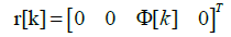
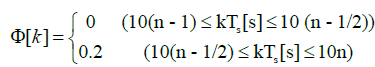
Since top priority parameter is given to the stability of control system, the angular velocity of the pendulum hich we confirmed from several experiments in advance, is set as QoS, and a code rate is determined according to it. One of the examples of setting QoS levels as three steps is shown in Figure 11. It shows the flow of the angular velocity of the pendulum velocity hen the reference value of the arm position φ(t) switches from 0[rad] to 0.2[rad] at the time t=5[s] without any communication error. The horizontal lines T (a|b) and T(0|a) in Figure 11 show the threshold values used at the code-rate determination. In general, the higher the code rate of an error correcting code is, the smaller overhead becomes, but tolerance to noise of wireless communication channel gets worse. Thus, we set the relationship among R0, Ra, and Rb as R0>Ra>Rb. Figure 12 shows the overview of feedback control for a rotary inverted pendulum.

Figure 11: An Example of QoS-HARQ: Code Rate Decision based on | θ | [5].
Performance evaluation
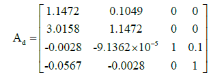
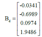
In Figure 12, the relationship between the controlled variable and the quantity of state in discrete time is described by the following formulas,

Figure 12: Block Diagram of Control Department in Wireless Feedback Control for a Rotary Inverted Pendulum [5].
X [k + 1]=AdX [k] + Bdu [k] (2)
u[k]=K (r[k] − X[k]) (3)
Where Ad and Bd are the parameters of a rotary inverted pendulum. They can be estimated from parameters listed at Table 1, and K is the feedback gain derived from the technique of LQR (Linear Quadratic Regulator) [6], which is as
 (4)
(4)
 (5)
(5)
K = [-14.2260 -2.6729 -0.1732 -0.2101] (6)
In addition, we suppose that the initial value of quantity of state X [0] and the desired value r[k] are given by
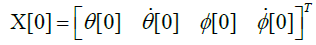 (7)
(7)
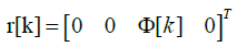 (8)
(8)
 (9)
(9)
n = 1, 2, . . . , 10
Controlled variables are assumed to be transmitted through wireless propagation channel, and the value in the time kTs is set to u[k]. Such controlled variables are created in the controller one after another, and transmitted immediately.
When the error of a packet is detected by the CRC check, the receiver in the controlled object inputs u[k] = 0 and requests retransmissions to the controller. Moreover, when the value of the angle of the pendulum becomes |θ(t)| > π/6, it will be regarded as the fall of the pendulum, and controlling will be over. In the proposal system, we have three steps of QoS by using different code rate R as follows.
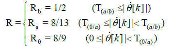 (10)
(10)
From Figures 13 and 14, we confirm our proposal can reduce the redundant bits in a packet while keeping the rotary inverted pendulum stable [7].

Figure 13: Transitions of Arm&pendulum's Position with QoS-HARQ [5]

Figure 14: Transition of the Number of Transmitted Bits with QoS-HARQ [5].
Future works
In addition, we are also thinking about the wireless visual feedback control system (Figure 15). In this system, a camera board is attached to the servo motor, and it tries to track the target object using the information transmitted thorough the uplink. If we think about the control for multiple UAVs, we can use not only the data gathered by radio wave but also by the camera. If we replace the controlled object by a drone, we’ll have to consider the situation in which there are several types of sensing data and controlling variables. By using the knowledge from the researches mentioned above, we’d like to consider the joint optimization problem for controlling multiple UAVs [8].

Figure 15: Wireless Feedback Control for a Rotary Camera [8].
Wireless Power Feeding
Overview of this section
In this section, we will consider microwave method WPT (Wireless Power Transmission) to improve drone’s flight time. It is being studied to use drones to rescue victims in circumstances such as disasters. However, the short flight time of Drone has become a problem. WPT attracts attention as one solution to this problem. WPT to the drone is mainly studied for the magnetic field resonance method and microwave because it can transmit from several tens of centimeters to several meters. In general, research on magnetic field resonance method has been actively conducted, because the power required for the drones to rotate the propeller is on the order of several hundred Watts, and it enables high power transmission compared to the microwave transmission method. However, the power transmission efficiency can be kept in the magnetic resonance type WPT, only when the power transmitted coil and the power received coil directly face each other like Figure 16. So, it is difficult to apply magnetic resonance method to the application like a drone whose power transmission direction changes by moving.

Figure 16: Image of Magnetic Resonance Method WPT to the Drone [9].
On the other hand, the direction of power transmission is changed by the technology of beam forming in microwave method WPT. In addition, drones whose power consumption is about 10 Watts have been developed [9], and it seems that the drone’s power consumption will be lower in the future. Furthermore, researches on increasing the power transmission capabilities of the rectenna are being conducted, and it is possible to rectify about 10 Watts with microwave method WPT [10]. Based on those reasons, the authors believe that the microwave WPT is effective as a feed system to the drone. The authors propose two systems on microwave method WPT.
Frequeucy adaptive WPT system: Although there are many studies about microwave WPT, WPT frequency are fixed in almost all studies [11]. However, the optimum frequency to achieve the maximum power transfer efficiency is different from use cases of microwave WPT systems.
The total efficiency of microwave WPT systems may change by WPT frequency due to the conversion efficiency of a rectenna, configurations of transmitting and receiving antennas, locations of a power transmitter and a receiver, and other conditions of its use case. Especially, highly efficient wireless power transmission independent of terminal position is essential for drones. Therefore, the authors propose a frequency adaptive microwave WPT system to maintain the total efficiency as a first study, and the concept of the proposed system is as follows,
– At first, get information/conditions of a WPT use case,
– Find out the optimum frequency to achieve the maximum power transfer efficiency,
– Set the optimum WPT frequency, and
– Check information/conditions of a WPT use case periodically and adjust WPT frequency.
Multihop WPT system: Although there are many studies about microwave WPT, power is transfered from starting point to the destination directly. However, since the power density of radio waves is inversely proportional to the square of the distance, there is a possibility that high-efficiency power transmission can be achieved by performing power transmission at a distance less than the distance where the effect of radio wave attenuation becomes dominant. To verify this assumption, the authors propose multi hop wireless power transmittion system for drone. As the first stage of research, the authors examined multi-hop WPT under circumstances where drone was placed at regular intervals.
In this section, in order to confirm the effectiveness of the proposed WPT systems, the result of simulation using a simple model is described. The total power efficiency is derived by the product of Power Transmission Efficiency (PTE) between the transmitting and receiving antennas, and Power Conversion Efficiency (PCE) while moving receiving terminal. The frequency characteristics of the total efficiency are discussed. And the authors confirmed the effectiveness of multi-hop WPT.
System model
Outline of the proposed system: The concept of the proposed system is shown as Figure 17. The transmitter decides the WPT frequency depending on the information of a receiving terminal. At the first step, the authors focus on the location of a receiving terminal as an important parameter to determine the optimum WPT frequency.

Figure 17: Concept of our Proposed Wireless Power Transmission System.
Transmitting antenna’s model: The ideal linear array antenna is selected as the transmitting antenna. Directional gain is expressed as in Eq(11).
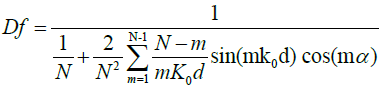 (11)
(11)
where k0 = λ/2π is wave number, α = −k0d cos(θ), N is the number of antenna elements, and d is the spacing between antenna elements. Using Df , PTE is expressed as the in Eq (12). PTE is defined as the ratio of the input microwave power to receiving antenna and output microwave power from transmitting antenna.
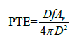 (12)
(12)
Where D is a distance between a transmitter and a receiver, Ar is aperture area of receiving antenna.
Rectenna’s model: When power is converted from RF to DC, rectenna which consists of recrifier and antenna is used. PCE is defined as the ratio of the output DC power and input maicro wave power. PCE is calculated by the Eq(13) as PCE[12,13].
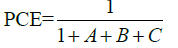 (13)
(13)
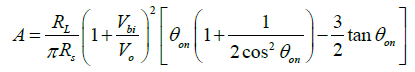
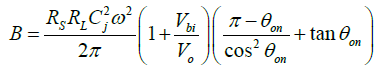
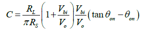
where Vo is the output self-bias DC voltage across the load, Vbi is the diode’s built-in voltage in the forward bias region, Rs is series resistance, and RL is DC load resistance, respectively. θon and Cj are expressed as Eq(14) and Eq(15).
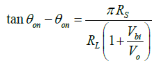 (14)
(14)
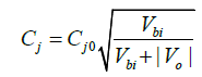 (15)
(15)
where Cj is a nonlinear junction capacitance and Cj0 is zero bias junction capacitance.
Simulation and consideration
Evaluation function and parameter: The parameters of the transmitting array antenna are listed at Table 3 and those of the rectenna are listed at Table 4. It is assumed that the rectenna always inputs the optimum input microwave power. Evaluation function is used in Eq(16). We find optimum frequency which maximizes the product of PTE and PCE when changing θ.
| Spacing of antenna elements [cm] | 10 |
| Number of antenna elements | 10 |
| Antenna element | Dipole antenna |
| Excitation amplitude | Equal |
| Aperture size of receiving antenna [cm2] | 10 |
| Distance between transmitter and receiver [cm] | 20 |
Table 3: Parameter of the Array Antenna.
| Series resistance Rs [Ω] | 4 |
| DC load resistance RL [Ω] | 50 |
| Diode’s built-in voltage in the forward bias region Vbi [V] | 0.7 |
| Output self-bias DC voltage across the load Vo[V] | 6 |
| Zero bias junction capacitance C0 [pF] | 0.02 |
Table 4: Paremeter og the tecenna[14]
f (θ, ω) = PTE ∗ PCE (16)
Simulation result: Figure 18 shows the optimum frequency to maximize the product of PTE and PCE the optimum frequency depends on the angle which is the direction of a receiver from a transmitter. The optimum frequency changes depending on the angle, because grating lobes occur in the higher frequency ranges. The optimum frequencies for each angle are shown in Table 5. Although there are five optimum frequencies, only two frequencies are selected to switch the frequency depending on the angle in Figure 19. The reason is that it is easier to make dual-frequency antenna elements. The Figure 19 shows the maximum efficiency when frequency is adaptively switched. The authors confirm that the proposed system can get good efficiency compared to using fixed frequency.
| θ | 90 | 75 | 60 | 45 | 30 | 15 |
| Frequency[GHz] | 1.6 | 1.8 | 1.8 | 4.2 | 4.8 | 2.8 |
Table 5: Optimum Frequency for each Angle.

Figure 18: Confirmation of the Optimum Frequency at Each Angle of the Antenna.

Figure 19: Maximum efficiency when Frequency is Adaptively Switched.
The Figure 20 shows the relationship between the number of hops and total efficiency which is the product of PTE and PCE. The authors do not consider the size and weight of the drones. Also, it is assumed that all drones are arranged in a straight line (Figure 21). The beam tilt angle was 90 degree (broad side direction), and the frequency is fixed at 3.4 GHz. The authors confirm that the proposed system can get good efficiency compared to WPT directly. But WPT directly is higher efficiency when the distance is 70 centimeter [14]. The authors are predicting that it is caused by the fact that if the distance between hops is long enough electric power cannot be transmitted, resulting in a decrease in efficiency of subsequent hops.

Figure 20: Relationship between Number of Hops and Efficiency versus Distance.

Figure21: Simulation Environment.
Conclusion
This paper describes an ongoing project on a comprehensive system of searching and rescuing victims by using multiple UAVs with wireless UWB technology for accurate localization and reliable vital sign data transmission for triage of victim care. Each step of this proposed system has been still investigated for theoretical optimization while trial experiments in Yokohama and Christchurch have been done. However, neither theoretical optimization nor practical experiment has been completed yet. The major purpose of this paper is to introduce the joint activities between Japan and New Zealand for a strategy of natural disaster. The current progress of each step has been introduced, and upon completion full results will be published separately. We hope this paper may be useful and helpful for any strategy for natural hazard and disaster.
Acknowledgement
The joint Japan and New Zealand Project is supported by the Bilateral Program (FY2016-FY2017) with funding from The Japan Society for the Promotion of Science, and The Royal Society of New Zealand (Grant JSPUOC1501- JR).
References
- Natsuki K, Fujinobu T, Ryuji K (2016) Improvement in Ionospheric Correction for Single- frequency GNSS Positioning. Int Jr of Trend Res Dev 3: 516-520.
- Natsuki K, Fujinobu T, Ryuji K (2017) Mitigation of Ionospheric Effect on Multi-GNSS Positioning with Ionosphere Delay Estimation Using Single-Frequency Measurements of Selected Satellites. Journal of Aeronautics, Astronautics and Aviation 49: 93-100.
- IEEE Standard for Local and metropolitan area networks, Wireless Body Area Networks.
- Masaki N, Natsuki K, Ryuji K (2017) 2-step UWB localization method using particle filter and geometrical condition with multiple UAVs in disaster IEICE Tech 117: 29-34.
- Seimiya S, Takabayashi K, Kohno R (2017) A Study for the Adaptive Error Correction Using QoS-HARQ toward Dependable Implant Body Area Network. 11th International Symposium on Medical Information and Communication Technology (ISMICT), Lisbon, Portugal.
- Kohinata R, Yamazato T, Katayama M (2009) Influence of channel errors on a wireless-controlled rotary inverted pendulum. IEICE Technical Report 108:167-172.
- Kohinata R, Yamazato T, Katayama M (2009) Influence of channel errors on a wireless-controlled rotary inverted pendulum. IEICE Technical Report 108:167-172.
- Seimiya S, Takabayashi K, Kohno R (2017) A Study for the Adaptive Error Correction in Wireless Vision Based Feedback Control under Implant Body Area Network. IEICE Technical Conference of Healthcare
- Yazdandoost KY, Sayrafian-Pour K (2009) Channel model for body area network, Wireless Personal Area Networks 15: 708-780.
- Samer A, Paul DM, Juan MA, George K, David CY (2017) Light-Weight Wireless Power Transfer for Mid- Air Charging of Drones. 11th European Conference on Antennas and Propagation, Paris, France.
- Seimiya S, Takabayashi K, Kohno R (2017) A Study for the Adaptive Error Correction in Wireless Vision Based Feedback Control under Implant Body Area Network. IEICE Technical Conference of Healthcare
- and Medical Information Technology, Paris, France.
- Samer A, Paul DM, Juan MA, George K, David CY (2017) Light-Weight Wireless Power Transfer for Mid- Air Charging of Drones. 11th European Conference on Antennas and Propagation, Paris, France.
- Takeshi M, Katsunori H, Naoki S (2000) Study of High Power Rectennas for Microwave Power Transmission. Inst of Elec Info and Comm Engg 83: 525-533.
- Brown WC (1980) The history of the development of the Rectenna. Rectenna Session of the SPS Microwave Systems Workshop, Lyndon B. Johnson Space Center, Houston, Texas, USA.